Medisoft Micro 5000 Instructions for use
Version 2.2
30/12/2019
H16-EN
HARDWARE USER MANUAL
Micro 5000

H16-EN Micro 5000 P
AGE
2/35
Con en
1
Foreword .................................................................................................................. 5
1.1
Foreword ..................................................................................................................... 5
1.2
Description of v il ble tests ...................................................................................... 6
1.3
List of st nd rd nd option l tests .............................................................................. 7
1.4
Intended users ............................................................................................................. 7
1.5
Environment l conditions............................................................................................ 7
2
Warnings ................................................................................................................... 8
2.1
Loc tion of the device ................................................................................................. 8
2.2
G s cylinders ................................................................................................................ 9
3
General overview .................................................................................................... 10
3.1
Front p nel................................................................................................................. 10
3.1.1
B sic version ............................................................................................................................... 10
3.1.2
Provo 4 option ............................................................................................................................ 11
3.1.3
RINT, MIP/MEP, P01 or compli nce option ................................................................................ 12
3.1.4
NEP option .................................................................................................................................. 13
3.1.5
SNIP option ................................................................................................................................. 14
3.2
Re r p nel .................................................................................................................. 15
3.3
H ndheld pneumot chogr ph .................................................................................. 16
4
Connec ions ............................................................................................................ 17
4.1
Connections on the front p nel ................................................................................. 17
4.1.1
All versions .................................................................................................................................. 17
4.1.2
Provo 4 option ............................................................................................................................ 18
4.1.3
MIP/MEP or RINT option ............................................................................................................ 18
4.1.4
NEP option .................................................................................................................................. 19
4.1.5
SNIP option ................................................................................................................................. 19
4.2
Connections on the re r p nel .................................................................................. 20
5
Calibra ion .............................................................................................................. 21
5.1
Foreword ................................................................................................................... 21
5.2
Prep ring the equipment .......................................................................................... 21
5.3
Initi lizing the c libr tion mode ................................................................................ 22
5.4
Volume c libr tion .................................................................................................... 24
5.4.1
C libr ting the pneumot chogr ph ............................................................................................ 24
5.4.2
Checking the pneumot chogr ph c libr tion ............................................................................. 30
6
Main enance ........................................................................................................... 32

H16-EN Micro 5000 P
AGE
3/35
6.1
Foreword ................................................................................................................... 32
6.2
M inten nce pl nning ............................................................................................... 33
6.3
M inten nce procedures for the user ...................................................................... 34
6.3.1
Cle ning ...................................................................................................................................... 34
6.3.2
Repl cement of the pneumot chogr ph mesh .......................................................................... 34

H16-EN Micro 5000 P
AGE
4/35
Revision
Da e
Version
Modifica ions
16/06/2014
1.0
Cre tion
01/06/2018
2.0
New design
14/05/2019
2.1
Modific tion of the CE m rking
30/12/2019
2.2
Removing redund nt inform tion’s

H16-EN Foreword P
AGE
5/35
1
1Foreword
1.1 Foreword
The Micro 5000 device is desk spirometer designed for st nd rd spirometry testing nd
respir tory function test (option l) th t rely on irw y pressure/resist nce me surements
for outdoor use nd routine pr ctice in sm ll office sp ce. The h ndheld spirometer is
suit ble for spirometry in clinic l context, ph rm cology nd epidemiology studies.
The Micro 5000 is oper ted by ExpAir, softw re progr m developed by Medisoft S.A. th t
functions on Windows b sed PC systems.
The Micro 5000 is m nuf ctured, c libr ted nd pplied in conformity with l test technic l
requirements nd offici l recommend tions by ATS nd ERS. The Micro 5000 spirometer
dopts the Lilly-type pneumot chogr ph technology for flow/volume me surement. With
the spirometry option, full we ther st tion (temper ture, humidity nd b rometric sensor)
for the correct determin tion of the BTPS correction f ctor is included.
On the following p ges, you will find the instructions needed to oper te your instrument
effectively for pr ctic l uses. Ple se re d this m nu l c refully before using the device for
the first time.
The content of this document is subject to periodic upd te nd revision. Ple se note th t
some items m y be modified slightly in l test version of the softw re.

H16-EN Foreword P
AGE
6/35
1
1.2 Descrip ion of available es s
The Micro 5000 device llows sever l types of me surement:
•Convention l spirometry
•Airw y resist nce
•Respir tory muscles function testing
Spirometry
The convention l spirometry includes:
•Slow spirometry with me surement of lung-volume subdivisions (VC, IC, ERV, Vt, RR,
VE)
•Forced expir tory m neuver (FEV1, FVC, PEF, intermedi te flows, FEF25-75…)
•M xim l volunt ry ventil tion test (MVV)
•Minute tid l ventil tion test (VE)
Airw y resist nce
The Micro 5000 device llows me suring the irw y resist nce by using the flow interruption
techniques (Rint). This technique is b sed on me surement of mouth pressure during irflow
occlusion.
Respir tory muscles function testing
The Micro 5000 device llows performing one of the following tests:
•Volition l techniques for studying respir tory muscle functions (MIP/MEP nd SNIP).
Those techniques re b sed on me surement of mouth pressure during m xim l
inspir tion/expir tion m neuvers nd n s l sniff inspir tory pressure.
•Volition l techniques for studying neuromuscul r drive (P0.1). This technique is
b sed on me surement of mouth pressure during irflow occlusion.
•Ventil tory flow limit tion by NEP (Neg tive expir tory pressure). This technique
combines flow-volume nd Venturi induced neg tive pressure.

H16-EN Foreword P
AGE
7/35
1
1.3 Lis of s andard and op ional es s
SPIROMETRY Abbrevia ion S andard/
op ional
Vit l C p city VC st nd rd
Forced Vit l C p city FVC st nd rd
M ximum volunt ry ventil tion MVV st nd rd
Minute tid l ventil tion VE st nd rd
Reversibility (pre/post) st nd rd
Ch llenge (only softw re) st nd rd
MECHANICS
Resist nce by flow interruption RINT option l
M xim l Inspir tory/Expir tory mouth Pressures MIP/MEP option l
Spont neous N s l Inspir tory Pressure SNIP option l
Lung compli nce (st tic, qu si st tic nd dyn mic) Compli nce option l
MECHANICS WITH NEURAL DRIVE
Occlusion pressure P01 option l
OTHER TESTS
Autom tic nebuliser for bronchoprovoc tion Provo 4 option l
Neg tive Expired Pressure NEP option l
1.4 In ended users
This device is to be used by physiologists, doctors, respir tory ther pists or nurses, or under
supervision of such. D t obt ined must be interpreted nd reported by tr ined medic l
st ff only.
1.5 Environmen al condi ions
This device is for clinic l use in hospit ls, priv te doctor’s offices, medic l schools, sports
medicine f cilities or universities.
The mbient conditions must be within the specified r nge:
•Temper ture: 10 to 35°C
•Humidity: 25 to 85% (non-condensed)
H16-EN W rnings P
AGE
8/35
2
2Warnings
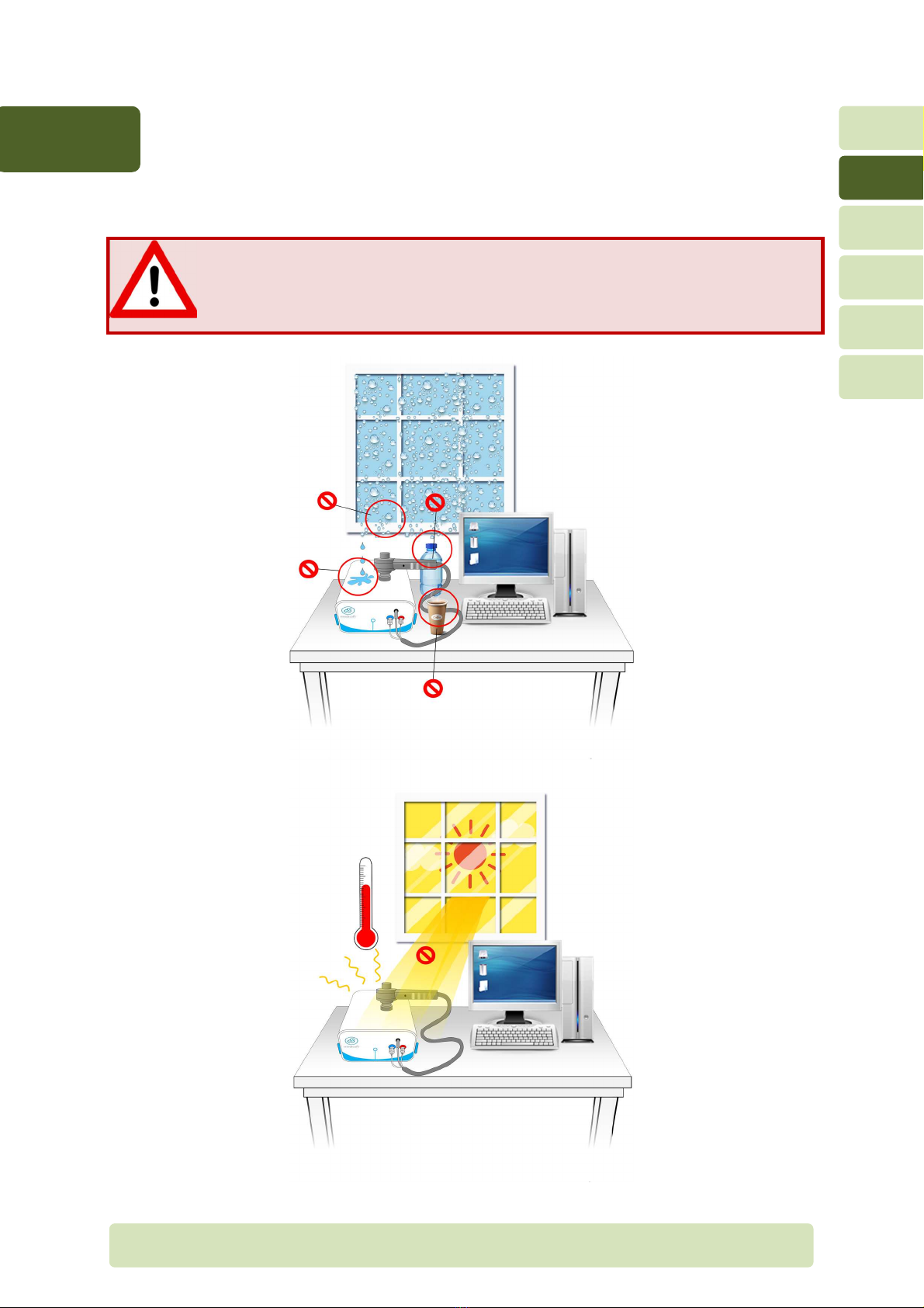
2.1 Loca ion of he device
Loca ion of he Micro 5000
The Micro 5000 module should not be loc ted on wet or dusty conditions.
The cooling ventil tor on the re r p nel must not be obstructed which could
le d to n overhe ting inside the module.

H16-EN W rnings P
AGE
9/35
2
2.2 Gas cylinders
If option NEP is v il ble on your system, the Micro 5000 device requires one g s cylinder.
Some recommend tions h ve to be followed c refully in order to void ny risk for the
p tient or the device.
Localiza ion of he gas cylinder
Do not pl ce compressed g s cylinder ne r the device. It might f ll by
ccident nd c use injuries to the p tient or the oper tor, nd d m ge the
device.
G s cylinders should be positioned t le st 2 meters from the device.
For better protection, the cylinder should be ch in locked to the w ll to
prevent it from f lling down.
Connec ion o he device
The connection of the g s cylinder to the device is under the full responsibility
of the user.
The length of the tube between the g s cylinder nd the module should not
exceed 3 meters.
H16-EN Gener l overview P
AGE
10/35
3
3General overview
3.1 Fron panel
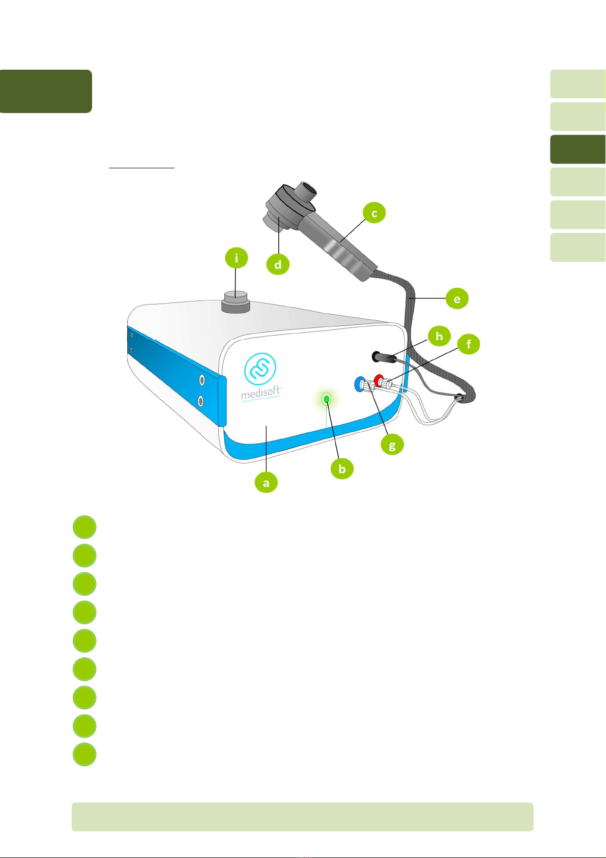
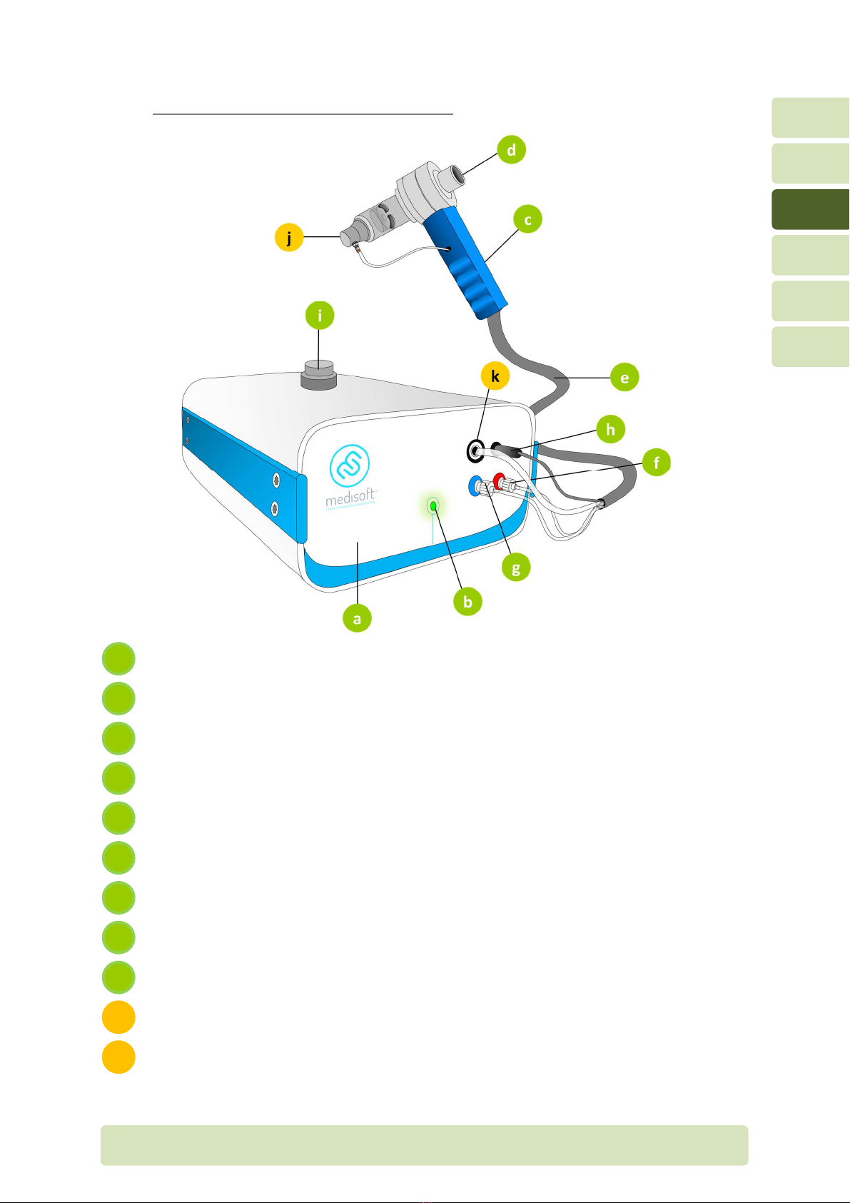
3.1.1 Basic version
Front p nel
Power LED
H ndheld spirometer
Lilly type pneumot chogr ph
Combined tubing for h ndheld spirometer
Upstre m flow connector (+, red)
Downstre m flow connector (-, blue)
He ted wire connector
Holder for pneumot chogr ph
i
h
g
f
e
d
c
b
a
H16-EN Gener l overview P
AGE
11/35
3
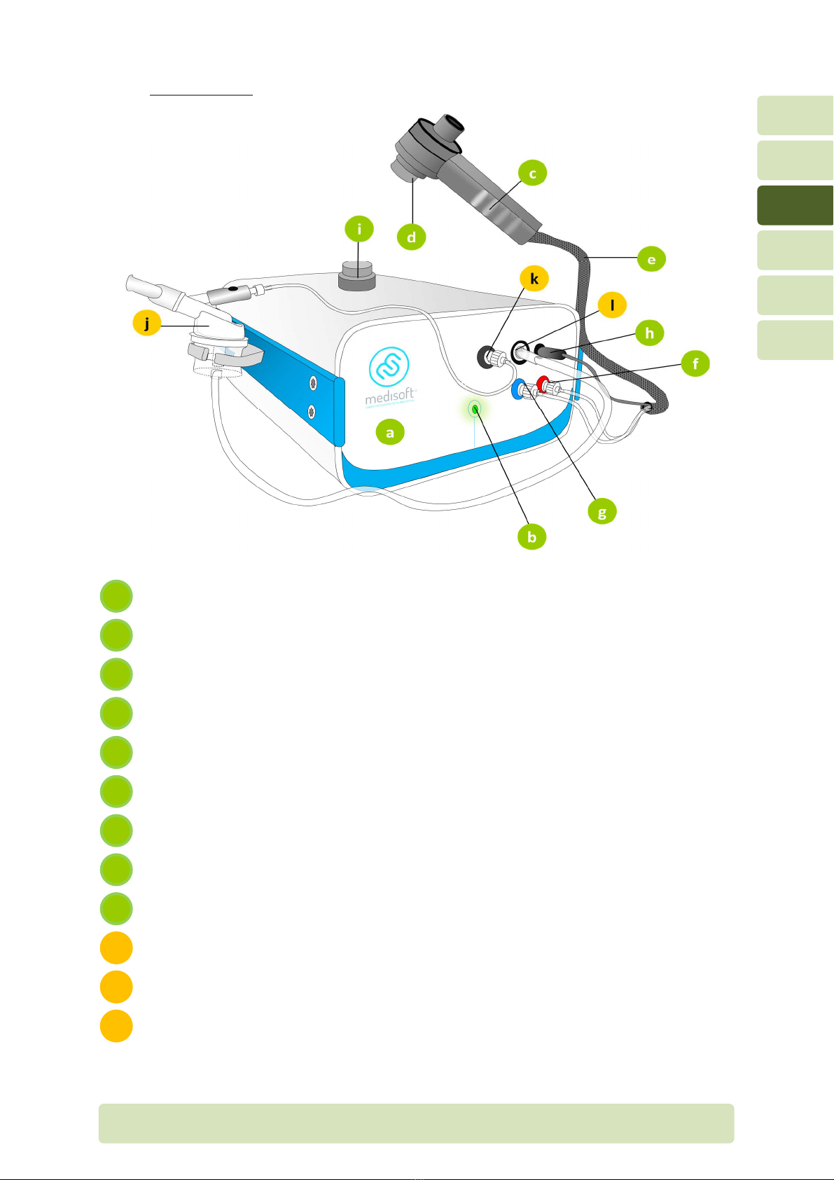
3.1.2 Provo 4 op ion
Front p nel
Power LED
H ndheld spirometer
Lilly type pneumot chogr ph
Combined tubing for h ndheld spirometer
Upstre m flow connector (+, red)
Downstre m flow connector (-, blue)
He ted wire connector
Holder for pneumot chogr ph
Nebulizer
Inlet for pressure me surement for nebuliz tion triggering
Outlet for nebuliz tion pressure
l
k
j
i
h
g
f
e
d
c
b
a
H16-EN Gener l overview P
AGE
12/35
3
3.1.3 RINT, MIP/MEP, P01 or compliance op ion
Front p nel
Power LED
H ndheld spirometer
Lilly type pneumot chogr ph
Combined tubing for h ndheld spirometer
Upstre m flow connector (+, red)
Downstre m flow connector (-, blue)
He ted wire connector
Holder for pneumot chogr ph
Shutter
Outlet for piston pressure supply
k
j
i
h
g
f
e
d
c
b
a

H16-EN Gener l overview P
AGE
13/35
3
3.1.4 NEP op ion
Front p nel
Power LED
H ndheld spirometer
Lilly type pneumot chogr ph
Combined tubing for h ndheld spirometer
Upstre m flow connector (+, red)
Downstre m flow connector (-, blue)
He ted wire connector
Holder for pneumot chogr ph
Venturi
Outlet for Venturi pressure supply
k
j
i
h
g
f
e
d
c
b
a

H16-EN Gener l overview P
AGE
14/35
3
3.1.5 SNIP op ion
Front p nel
Power LED
H ndheld spirometer
Lilly type pneumot chogr ph
Combined tubing for h ndheld spirometer
Upstre m flow connector (+, red)
Downstre m flow connector (-, blue)
He ted wire connector
Holder for pneumot chogr ph
C theter SNIP
j
i
h
g
f
e
d
c
b
a

H16-EN Gener l overview P
AGE
15/35
3
3.2 Rear panel
Re r p nel
Cooling f n
Seri l communic tion port (connected to computer)
Thermometer sensor
Humidity sensor
Power switch (ON/OFF)
Power supply entry
G s inlet for nebuliser (Provo 4 option) or piston supply (MIP/MEP, RINT, P01
or NEP option)
h
g
f
e
d
c
b
a
H16-EN Gener l overview P
AGE
16/35
3
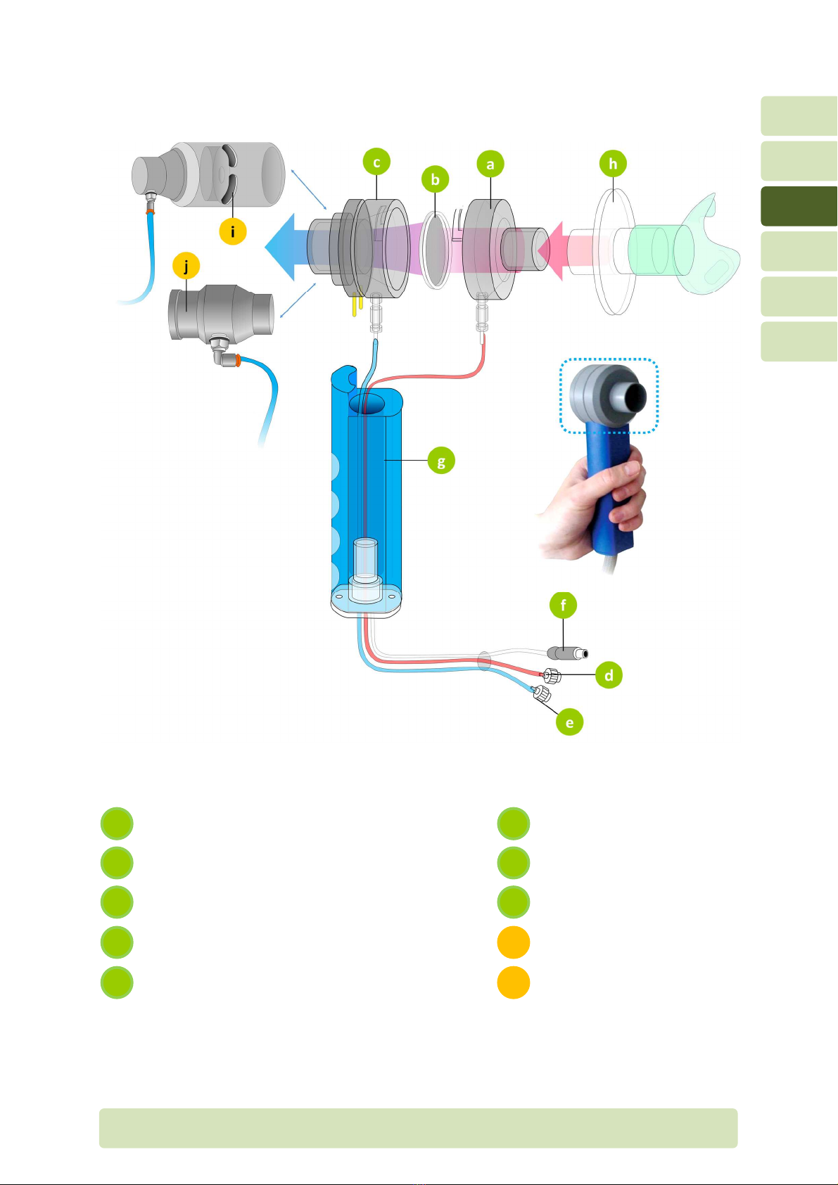
3.3 Handheld pneumo achograph
Pneumot chogr ph front p rt (p tient f cing)
He ted wire nd plug
Pneumot chogr ph mesh
H ndle
Pneumot chogr ph b ck p rt (to mbient)
Antib cteri l/vir l filter
Upstre m flow line nd connector (+, red)
Shutter for MIP/MEP, RINT or P01
option
Downstre m flow line nd connector (-, blue)
Venturi for NEP option
j
e
i
d
h
c
g
b
f
a

H16-EN Connections P
AGE
17/35
4
4Connec ions
4.1 Connec ions on he fron panel
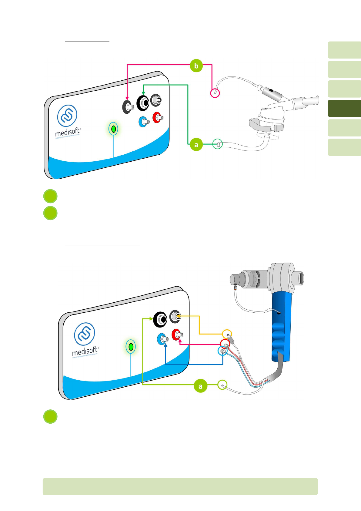
4.1.1 All versions
Insert the plug-in connectors to the upstre m (red)/downstre m (blue) ports
Secure the connection by clockwise rot tion of the plug-in connectors
Plug the he ted wire
3
2
1
H16-EN Connections P
AGE
18/35
4
4.1.2 Provo 4 op ion
Connection to pressure me surement for nebuliz tion triggering
Connection for nebuliz tion pressure
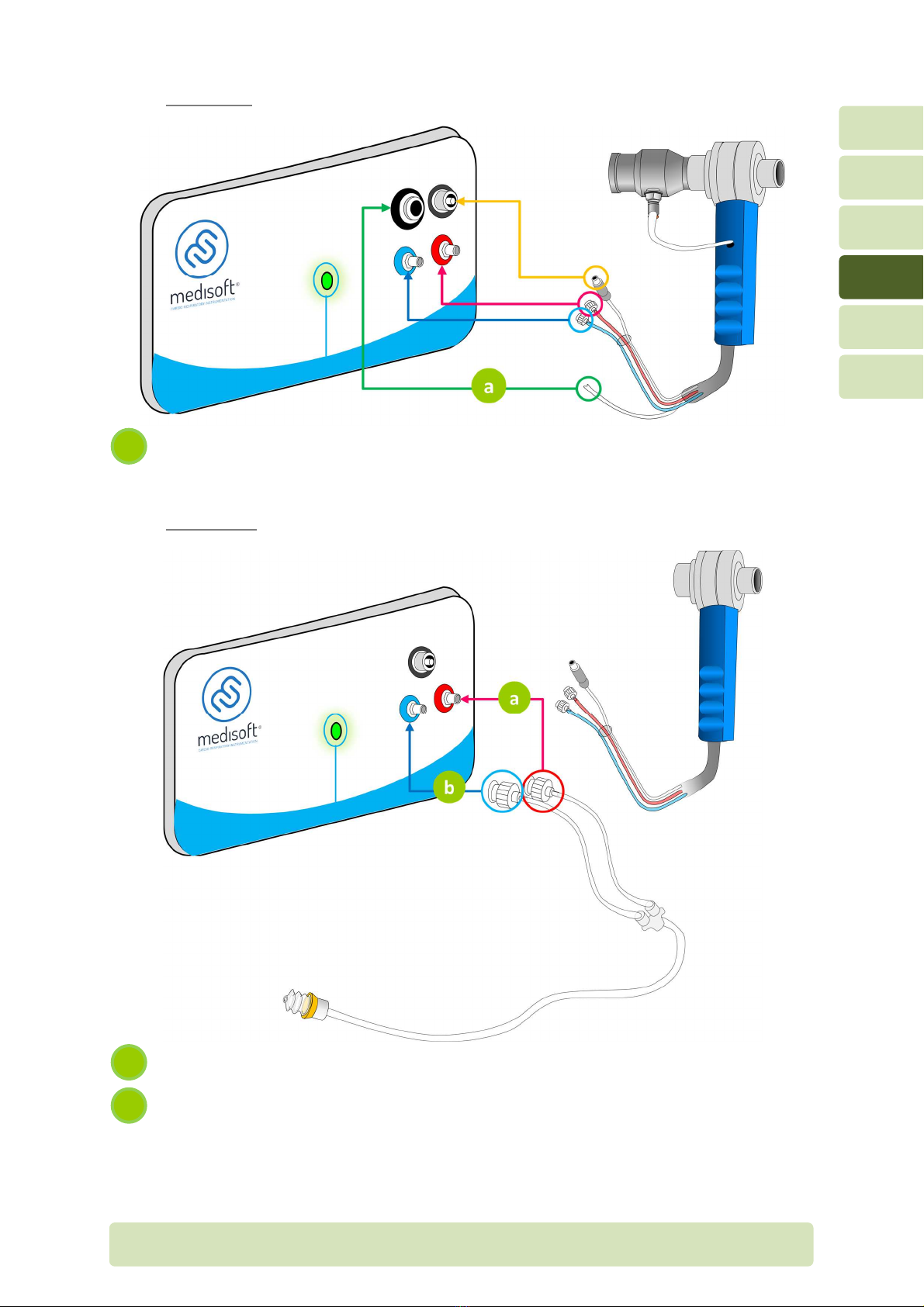
4.1.3 MIP/MEP or RINT op ion
Connection for piston pressure supply
a
b
a
H16-EN Connections P
AGE
19/35
4
4.1.4 NEP op ion
Connection for Venturi pressure supply
4.1.5 SNIP op ion
Upstre m flow connector (+, red)
Downstre m flow connector (-, blue)
b
a
a
H16-EN Connections P
AGE
20/35
4
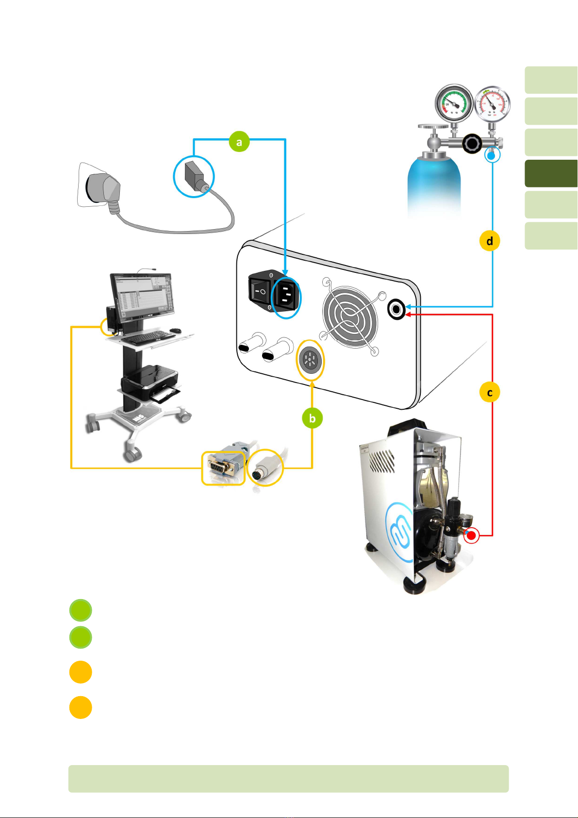
4.2 Connec ions on he rear panel
Power supply c ble
Seri l communic tion c ble
For Provo 4, MIP/MEP, P01, RINT or compliance option
Connection to compressor (3.5 b r – 50 psi)
For NEP option
Connection to compressed ir bottle (6 b r – 87 psi)
d
c
b
a
Table of contents
Other Medisoft Medical Equipment manuals


Popular Medical Equipment manuals by other brands


Getinge
Getinge Arjohuntleigh Nimbus 3 Professional Instructions for use

Mettler Electronics
Mettler Electronics Sonicator 730 Maintenance manual

Pressalit Care
Pressalit Care R1100 Mounting instruction

Denas MS
Denas MS DENAS-T operating manual

bort medical
bort medical ActiveColor quick guide

AccuVein
AccuVein AV400 user manual


