Drive PreserveTech Harmony True 14200N User manual

www.drivemedical.com
Item # 14200N
Mattress Replacement System with Digital Pump
Système de remplacement de matelas avec pompe numérique
Sistema de colchón de reemplazo con bomba digital
Harmony True Low Air Loss Tri-Therapy
Mattress Replacement System
USER MANUAL
Système de remplacement de matelas HARMONY
trithérapie à faible perte d’air véritable
MANUEL DE L’UTILISATEUR
Sistema de colchón de reemplazo HARMONY con
baja pérdida de aire real con tres tratamientos
MANUAL DEL USUARIO

2
TABLE OF CONTENTS
IMPORTANT PRECAUTIONS .............................................................................................................3
DOCUMENT SYMBOLS ......................................................................................................................3
INTRODUCTION..................................................................................................................................5
UNPACKING YOUR HARMONY .........................................................................................................6
PRODUCT FEATURES ........................................................................................................................7
Control Unit ...................................................................................................................................7
Mattress.........................................................................................................................................8
PRODUCT FUNCTION ........................................................................................................................9
Control Unit ...................................................................................................................................9
Mattress.......................................................................................................................................10
OPERATION. .....................................................................................................................................12
General........................................................................................................................................12
CPR function ...............................................................................................................................13
Pressure Range Selection...........................................................................................................13
PATIENT POSITIONING AND COMFORT.........................................................................................14
CLEANING AND MAINTENANCE .....................................................................................................15
TROUBLESHOOTING .......................................................................................................................17
SPECIFICATIONS..............................................................................................................................18
WARRANTY.......................................................................................................................................19
This manual should be used for the initial set up of the system and for future reference.

3
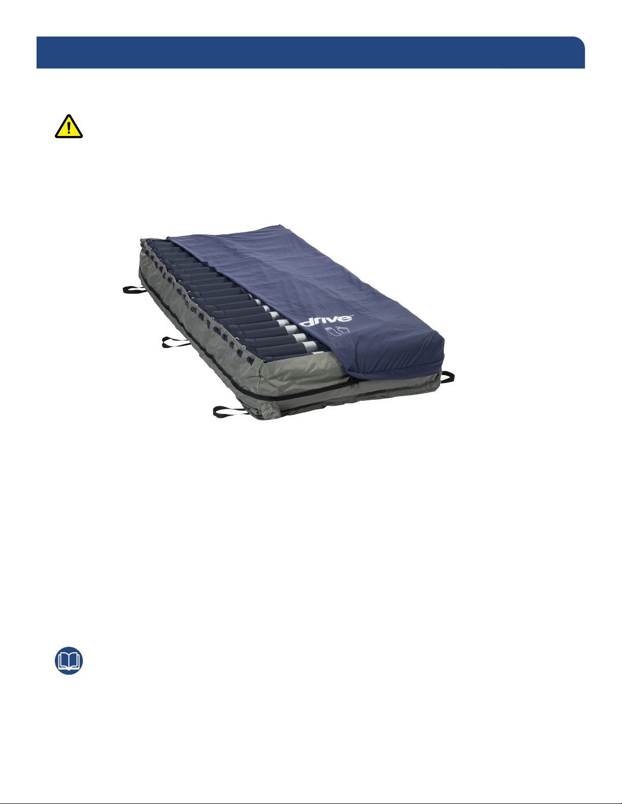
The Harmony, Tri-Therapy Mattress Replacement System, is a Class 2 medical device and that must
be installed and operated in the manner for which it was intended. The user is responsible for reading
and understanding the product user manual. Drive DeVilbiss Healthcare is not responsible for any
injuries resulting from failure to comply with the instructions and precautions in this manual.
Danger
Do not use in the presence of ammable anesthetics. Do not use in the presence of smoking materials
or open ames. Air owing through the mattress will support combustion.
Danger
To reduce the risk of electrocution, adhere to the following instructions. Failure to do so could result in
personal injury or equipment damage.
• Immediately after using the Harmony System, unplug this product from its power source.
• Do not place or store product where it can fall or be pulled into a tub or sink.
• Do not place in or drop into water or other liquids.
• Do not open the control unit without referring to Drive DeVilbiss technical service department rst.
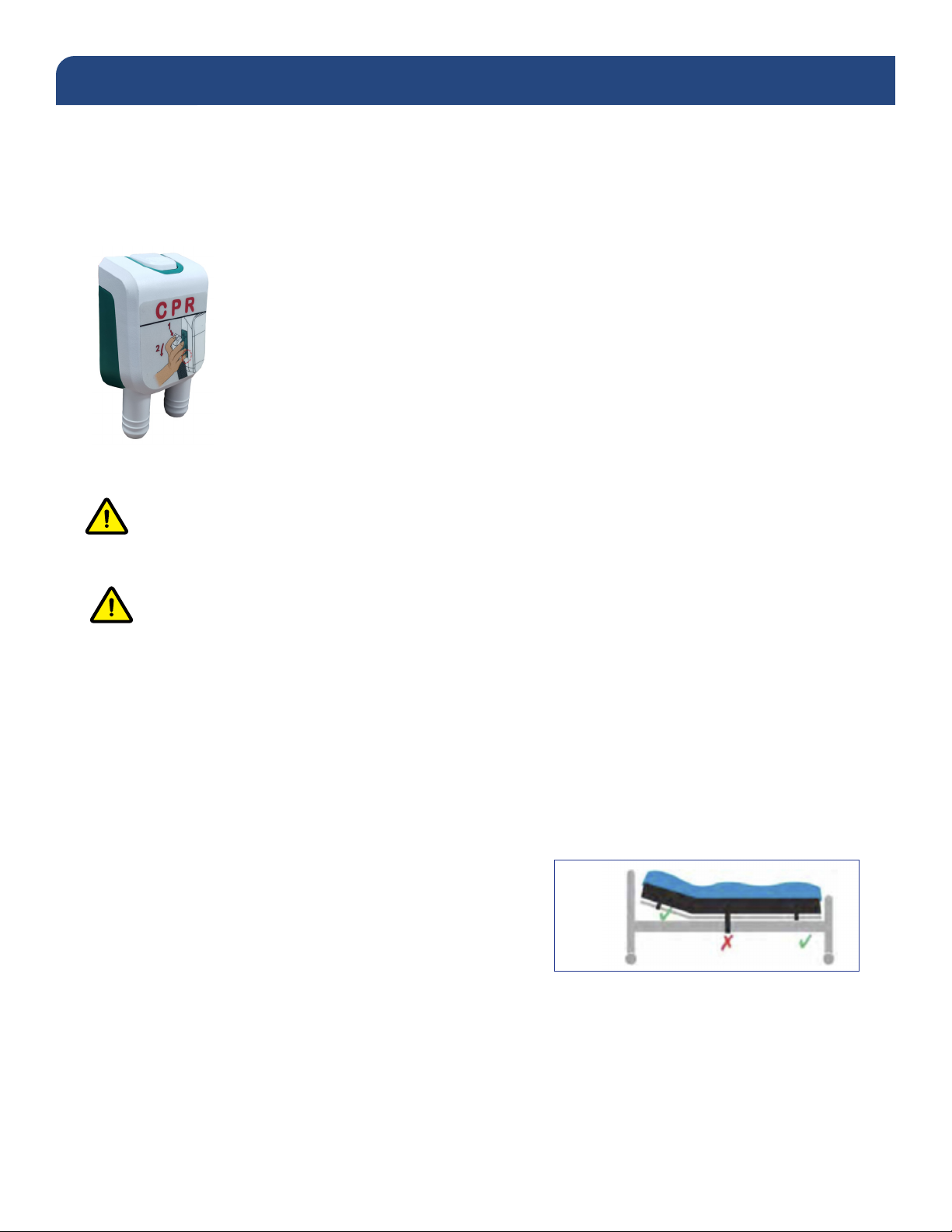
Warning
Do not strap the mattress to the bed frame at the head and foot ends. Secure mattress straps to the
bed deck at the head and foot ends and to the bed frame at the center of the bed.
Warning
To reduce the risk of burns, electrocution, re, or injury, adhere to the following instructions. Failure to
do so could result in personal injury or equipment damage.
• This product should only be used for its intended purpose as described in this manual.
• Only use attachments and /or accessories that are recommended by the manufacturer.
• Do not use this product if it has a damaged cord or plug, if it is not working properly, if it has been
dropped, damaged, or immersed in water. Return to your provider for a warranty claim.
• Keep the cord away from heated surfaces, i.e. space heaters.
• Never block the air openings of the product or place it on a soft surface, such as a bed or couch,
where the air openings may be blocked. Keep the air openings free of debris such as lint and hair.
• Never drop or insert any object into any opening or hose.
• Do not use outdoors or operate where aerosol (spray) products are used.
• Connect this product to a properly grounded outlet only.
• Do not spill food or liquids onto the control unit. If a spillage does occur, turn off the unit, disconnect
it from its power supply and allow at least 24 hours for drying.
IMPORTANT PRECAUTIONS

4
IMPORTANT PRECAUTIONS
Warning
Drive DeVilbiss Healthcare support surfaces are designed as mattress replacement systems. The risk of
entrapment may occur when mattresses are placed on bed frames that do not properly t and leave gaps
between the mattress and head panel, foot panel and bed or side rails. This system is NOT to be used
when such gaps are present.
User/Facility staff are responsible for ensuring that all mattresses properly t the bed frames. Drive
DeVilbiss is not responsible for the improper placement of its systems on ill-tting bed frames. Health care
professionals assigned to each patient should make the nal determination whether side or assist rails are
warranted after assessing patient risks based on the individual’s needs and condition.
An optimal bed system assessment should be conducted on each patient by a qualied clinician or
medical provider to ensure maximum safety. The assessment should be conducted in compliance with
the state and federal guidelines related to the uses of restraints and bed system entrapment guidance
including but not limited to the below:
1) US FDA Entrapment Guidelines. “A Guide to Bed Safety,” https://www.fda.gov/medical-devices/
hospital-beds/guide-bed-safety-bed-rails-hospitals-nursing-homes-and-home-health-care-facts
2) US FDA Hospital Bed System Dimensional and Assessment Guidance to Reduce Bed Entrapment,
https://www.fda.gov/regulatory-information/search-fda-guidance-documents/hospital-bed-
systemdimensional-and-assessment-guidance-reduce-entrapment
OPERATING INSTRUCTIONS
Indicates correct operating or maintenance procedure in order to prevent damage to or destruction of
the equipment.
Note
Indicates tips or information users should be aware of.
Caution
Indicates a potentially hazardous situation which, if not avoided, could result in property damage or minor
injury or both.
Warning
Indicates a potentially hazardous situation which, if not avoided, could result in death or serious injury.
Danger
Indicates an imminently hazardous situation which, if not avoided, will result in death or serious injury.
DOCUMENT SYMBOLS

5
INTRODUCTION
Pressure injuries are dened as localized injuries of the skin and/or underlying tissue over a bony
prominence as a result of pressure or pressure in combination with shear. Support surfaces or specialized
mattress systems are used as part of an overall, multi-disciplinary, multi-dimensional care plan intended to
prevent and treat pressure injuries.
The Harmony support surface is a high quality, tri-therapy active blower system that combines true low air
loss and dynamic alternating pressure. Specically designed for the prevention and treatment of pressure
injuries, while optimizing patient comfort.
Indications for Use
Effective pressure redistribution therapy, wound management and device selection should be based on
the patient’s specic clinical condition and complete assessment of needs, recognizing that pressure
prevention devices are only one component of a comprehensive pressure injury management program.
Support surfaces are not substitutes for turning, repositioning or functional weight shifts by caregivers.
The Harmony, Tri-Therapy Mattress Replacement System is intended for:
1) Pressure redistribution for individuals with but not limited to the following conditions:
2) Shear & Friction Reduction:
Friction is dened as the resistance of motion in a parallel direction relative to the common boundary of two
surfaces. For patients this can occur when the skin rubs against another surface.
Shear (or shear stress) is the force per unit area exerted parallel to the perpendicular plane of interest.
Shear strain occurs when skin is distorted or deformed as a result of shear stress.
3) Spinal Cord Injury:
The Harmony system can be used for patients with spinal cord injury once the acute injury has been
stabilized and these patients have been assessed and cleared by the appropriate clinician.
These instructions and recommendations are in accordance with the 2019 Clinical Practice Guidelines of
the National Pressure Injury Advisory Panel (NPIAP), the European Pressure Ulcer Advisory Panel (EPUAP)
and the Pan Pacic Pressure Injury Alliance (PPPIA).
Contraindications
Patient conditions for which the application of pressure relieving therapy on a true low air loss, blower-
based system is contraindicated are as follows:
1) Unstable spinal cord injuries
• At risk for or present pressure injuries
• Neurological conditions
• Amputations
• Grafts
• Burns
• Dermatological conditions
• Flaps
• Rehabilitation needs
• Pain management as prescribed by a
physician.

6
The Harmony, Tri-Therapy Mattress Replacement System is comprised of two components:
1) Therapy Air Cell Mattress
2) Therapy Control Unit
Control Unit: Digital System
• This digital control unit includes intuitive controls for adjusting the air pressure based on the patient’s
weight and comfort levels.
• Blower based system has a maximum airow of 1300L/minute, providing true low air loss for optimal
microclimate control helping to keep the patient cool and dry.
• Low pressure, power failure, and system failure visual and audible indicators allow the user to be aware
of any air pressure changes, power outages or system failures, respectively.
• Pulsation mode periodically increases and decreases air pressure every 15 seconds, encouraging
lymph and blood ow for increased oxygenation.
• CPR connector allows for rapid deation.
• Mute button available for silencing information signal.
• Cycle times are available to customize the therapy duration.
UNPACKING YOUR HARMONY
1) Carefully remove all components from packaging.
2) Conrm that you have received the control unit intended.
3) Check all components for damages. Contact your medical provider if any components are damaged.
DO NOT use damaged components.
PRODUCT FEATURES

7
Mattress
Warning
When using a therapy mattress system, always ensure that the patient is positioned properly within
the connes of the bed. The patient’s head should be positioned in the center of the top section of the
therapy mattress. Do not let any extremities protrude over the side or between the bed rails when the
therapy mattress is being used.
• 20 individual 8” deep air cells over a 2” foam base provide power outage protection in the event of a
power failure.
• Breathable, moisture vapor permeable, four-way stretch mattress cover allows air to circulate beneath
the patient and wicks away heat and moisture.
• Mattress cover is manufactured with an anti-microbial* agent that helps to minimize the growth of stain
and odor-causing bacteria, mold, mildew, fungus, and algae on treated surfaces.
• Quick cell disconnects offer convenient servicing and inate in under two minutes with auto rm
feature for quick delivery and easy set up.
• Five loops on the side of mattress offer cable management, and snap t buckle strap on the bottom of
mattress allow the system to be wrapped into a compact size for quick and easy storage.
• Able to accommodate patients up to 550 lbs.
Note
Please be sure to read this manual in its entirety before attempting to set up and operate this system.
*Antimicrobial properties are built in to protect the products. These products do not protect users or others against bacteria, viruses, germs,
or other disease organisms. EPA registration 92760-9 is Ultra-Fresh DW-30, which is registered to control the growth of fungi, bacteria and
algae in polyurethane foams, rubber, non-aqueous coatings, adhesives, PVC and grout mortar and mastics.
.
PRODUCT FEATURES

8
PRODUCT FUNCTION
Control Unit
Power switch is located on the side of the control unit. Use the power switch to turn the system off and on.
Power Button (1)
• Press the Power button on the panel, the pump will start/stop operation.
Weight Settings (2)
• Weight settings can be used to adjust the pressure of the inated cells based on the
patient’s weight and comfort level.
• For extra rm support during patient ingress and egress, patient wound care or cleaning,
it is recommended to set the comfort level to auto rm.
Mute Button (3)
• The audible/visible information signal turns on when low pressure or power failure occur.
• To mute the audible information signal, press the Mute button. The visible information
signal indicator will continue ashing until the issue is resolved.
• Re-press the Mute button to reactivate the information signal.
Cycle Time (4)
• The cycle time can be selected from the panel to choose the appropriate cycle time of the
ination modes.
• The cycle time value options are: 5, 10, 15 or 20 minutes.
Alternate Mode (5)
• Press the alternate button on the panel to set the system to alternation therapy mode. The
system will remain 1-in-2 alternating cell cycle to achieve periodic pressure relief.
Static mode (6)
• Press the select static button on the panel to set the system to static therapy mode. The
system will remain at the constant desired patient comfort level.
Pulsation Mode (7)
• Press the pulsation button on the panel to set the system to pulsation therapy mode. The
air cells pulsate between a decreased and increased pressure level every 15 seconds
. SeatInate(8)
• Press the seat inate button on the panel to set the air mattress to seat (fowler) mode.
The pressure value will increase to facilitate more comfortable seating.

(3)(2) (4)
(8) (9)(7)(6)(5) (10) (1)
9
PRODUCT FUNCTION
Auto Firm (9)
• The system will go into auto rm mode automatically when the power button is selected.
This ensures the control unit reaches its maximum operating pressure. Maximum airow
of 1300L/minute quickly inates the air cells in 2 minutes.
• Once the maximum pressure level is reached, the control unit will automatically switch to
previously selected comfort level in STATIC mode after 20 minutes, or the user can press
the THERAPY mode button to select another therapy such as alternation or pulsation.
• Press to set the air mattress back into quick ination mode, which facilitates nursing
and caring.
Lock Button (10)
• Auto: control unit panel automatically locks in 5 minutes without operation.
• Manual: press lock button for 3 seconds to lock the panel, press again for 3 seconds to
unlock the panel.
Mattress
• The Harmony mattress replacement comes with a hose connection at the foot end of the mattress with
20 individual, 8” deep air cells over a 2” foam base providing power outage protection.
• Tri-therapy combination active system incorporates the functions of true low air loss technology,
alternation, and pulsation therapy to optimize pressure redistribution, reduce shear and friction while
providing microclimate control to keep the patient cool and dry.
• Removable, four way stretch Polyurethane/Polyester fabric cover is manufactured with an anti-microbial*
agent and is uid resistant, low shear and vapor permeable helping protect the skin from friction and
moisture.
*Antimicrobial properties are built in to protect the products. These products do not protect users or others against bacteria, viruses, germs, or
other disease organisms. EPA registration 92760-9 is Ultra-Fresh DW-30, which is registered to control the growth of fungi, bacteria and algae in
polyurethane foams, rubber, non-aqueous coatings, adhesives, PVC and grout mortar and mastics.

5)
10
PRODUCT FUNCTION
• The cell material, PU/Nylon blend, provides a specialty surface that conforms to the specic shape of the
patient, minimizing soft tissue distortion, reducing bone penetration into muscle fascia, and promoting
improved blow ow compared to traditional surfaces.
. CPRdeationvalve
• Remove the quick connector on the left side of control unit to release the air
immediately from the mattress for rapid deation. Deation time varies depending
on patient weight and prole..
Quick Connector
• Used to connect the therapy mattress to the control unit.
Warning
For important precautions, see pages three and four
Caution
Do not place the control unit on the oor. Position the power cord to prevent tripping hazards.
1) Remove all existing covers and sheets from mattress on bed.
2) Unpack the Harmony, tri-therapy mattress replacement system and inspect all components for damage.
Do NOT use the system if any component is damaged.
3) Conrm there are no sharp objects in the immediate area which may risk damage to the Mattress.
4) Position the Lateral Rotation Mattress Replacement on
top of bed, printed top cover facing upwards and
air hoses towards the foot end of the bed.
5) Secure the therapy mattress to the movable parts of the
bed frame or bed deck. Ensure buckles are securely
fastened and straps are pulled tightly.
DO NOT SECURE TO THE SIDE RAILS - STRAPS
WILL TEAR OFF.

a)
b)
c)
11
a) Position the control unit by hanging hooks over foot
board of the bed.
b) Attach the air hoses to the therapy mattress securely
using the quick connector. When properly installed,
the quick connector will audibly click into place.
Ensure air hoses do not kink between mattress,
bed frame and control unit.
c) Plug the power cord into an electrical outlet with
AC power.
Note
Before inserting the plug into the outlet, make sure the
voltage is compatible and the product is well grounded.
d) Switch the power switch on the side of the control unit on.
The mattress replacement system quickly inates in
under 2 minutes with auto rm feature.
PRODUCT FUNCTION

12
Note
Always read the operating instructions in this manual before use.
General
This product is designed to provide pressure redistribution while maximizing comfort to patients. Please
be sure to operate this equipment as instructed to optimize its value. Please be sure to follow the
instructions corresponding to the control unit being used.
Note
Please follow instructions below for detailed operating procedure.
Digital Control Unit Operation
Step 1 Turn on the power switch located on the side of the control unit. Next, press the power
button on the front of the control panel. A beep will sound to alert that the system is on.
Step 2 The control unit will automatically default to auto rm mode of therapy and begin inating.
The blower style pump rapidly inates the mattress in approximately 2 minutes. If full
ination is not reached within 3 minutes, the low-pressure information signal will illuminate.
Press the mute button to mute the information signal. The information signal LED will
continue ashing. Press the mute button again to re-enable the audible information signal.
Step 3 Once fully inated, the control unit will switch into alternate therapy mode at the default
setting. Select desired settings from the touch panel to adjust the cycle time and pressure
level to the patients’ specic requirements.
Note
Press the auto rm mode button from the touch panel to provide a rm surface that makes it easier for the
patient to transfer or reposition. The system will revert to the previously selected therapy mode after 20
minutes.
Note
During normal operation, the unit will monitor pressure. If the mattress pressure is lower than the set pressure,
the pump will automatically inate the mattress to readjust to the set level. The alarm will beep, and its LED will
come on to alert a low-pressure condition. Press the Mute button to mute the information signal. The information
signal LED will continue ashing. Press the Mute button again to re-enable the audible information signal.
OPERATION

13
OPERATION
Note
For suitable pressure, please refer to page 14 for the hand check procedure.
CPR function
When there is an emergency requirement to perform CPR on the patient, remove the quick connector at
the left-hand side of the control unit to release the air quickly from the mattress.
Pressure range selection (+/-)
Users can adjust the pressure level of the air mattress, using the (+) and (-) buttons, to a desired rmness
based on personal comfort or weight setting.
Note
This system will automatically default to auto rm when the mattress is rst inated. Users can then easily
adjust the air mattress to a desired rmness according to the patient’s weight and comfort.
Low pressure indicator
When the air pressure in the system falls below the selected pressure range, a low-pressure condition will
signal the low-pressure indicator. Check if the connections are secure and correctly installed according to
the relevant instructions.
Note
If the pressure is consistently low, open the zipper and conrm that all the hoses are properly connected.
Then check for any noticeable leakage in any of the tubes. If necessary, contact your local dealer to
replace any damaged tubes or hoses.

14
General Repositioning
Patients should be turned or repositioned based on their individually planned treatment schedule or per
facility policy. Support surfaces are not substitutes for turning/repositioning or functional weight shifts.
Hand Check Procedure:
A suitable way to verify that the patient is not bottoming out is to perform a hand check as described below:
1) Ensure that the patient is lying supine (on his/her back) in the middle of the mattress.
2) Place a hand with four (4) ngers stacked vertically beneath the air cell directly underneath the sacral region.
3) Ensure that the 4 ngers can slide with minimal resistance between the patients’ sacral region and the
lower portion of the mattress.
4) Adjust the comfort setting as needs.
5) Wait for the mattress to adjust to the selected range.
6) Revaluate with the hand check and adjust to patients’ comfort level.
Recommended Linen:
Drive DeVilbiss Healthcare bed support surfaces are designed to be used with appropriate linens. Deep
pocketed tted or at sheets are recommended. Multiple layering of linens or underpads beneath the
patient should be avoided, when possible, for the prevention and treatment of pressure injuries.
Incontinence
Moisture against the skin surface is an extrinsic risk factor for acquiring a pressure injury as it weakens
the skin tissue leading to maceration. To protect skin integrity, incontinence barrier pads may be used to
absorb excess moisture.
Warning
Specialty active and reactive support surfaces are designed to redistribute pressure and reduce shearing/
friction forces against the patients’skin. Patient migration is possible due to the nature of these products.
Always ensure the patient is positioned properly within the connes of the bed and specialty system.
PATIENTPOSITIONINGANDCOMFORT

15
CLEANING & MAINTENANCE
Note
It is important to follow these procedures before using the system or between patient use.
Control Unit
Caution
DO NOT immerse or soak the control unit in any water or uids.
DO NOT spray any cleaning solution directly on the surface of the control unit.
DO NOT use a Phenolic based cleaning solution as this may cause damage to the case.
1) UNPLUG the control unit from its power source prior to cleaning.
2) Check for external damage and move the control unit to the cleaning area.
3) Place the control unit on a work surface and wipe the outside of the case with a clean cloth to remove
any dust or particles. Make sure all areas are clean (top and bottom, both sides).
4) Spray cloth with cleaning solution and clean faceplate and control unit casing. DO NOT allow excess
cleaning solution on faceplate or control panel. (If solution gets inside, damage will occur.)
a. Quaternary ammonium solution may be used.
5) After the control unit is thoroughly cleaned and dried, proceed to plug in the control unit and test for normal
functioning.
6) Unplug the control unit and store with proper identication tag until needed for use.
7) Avoid long exposure to sunlight.
Mattress
1) Remove any soiled or used bedding.
2) Examine the mattress for visible soilage of bodily uids.
3) If no disinfection is required, brush off or wipe down all surfaces of the cover sheet with soap and water
before wetting with any liquid disinfectant.
4) If disinfection is required, follow the procedure below:
a. Use rubber gloves and eye protection.
b. Unzip the top cover from the mattress.
c. Prepare detergent/disinfectant solution (registered by the EPA recommended) according to
the preparation recommended for correct use-dilution.
d. 1:9 Bleach and water dilution may be used.
e. With the mattress fully deated, wipe down all surfaces around and in between the air cells,
including the cells.

16
f. Covers may be immersed and soaked in disinfectant for the required incubation period. After
pre-soaking, the cover may be rinsed through a regular cycle in a washer with no soap then
laundered with mild detergent (wash temperature 93°F/34°C, rinse temperature 78°F/26°C or
on the coldest setting).
g. Allow all covers and parts to aerate until they are fully dry.
5) Repeat the process with the tubing set: spray/wipe, incubate, and air dry.
6) Dry the mattress on a at surface area after cleaning, away from exposure to the sun.
7) Avoid long exposure to sunlight.
HANDLING AND STORAGE
• Lay the mattress out at and upside down.
• Roll from the foot end towards the head end; the foot-end strap can then be stretched around the rolled
mattress to prevent unrolling.
• Do not fold, crease, or stack the mattress.
• Place the complete system into the carry bag. Do not store in direct sunlight, extreme high or low
temperatures or moist area.
MAINTENANCE
General
• Check the power cord and plug to see if there are abrasions or excessive wear.
• Check the mattress cover for signs of wear or damage. Ensure the mattress cover and tubes are
connected correctly.
• Plug in the control unit and check the airow from the hose connection port. The airow should alternate
between ports every half-cycle time.
• Check the air hoses to see if there are any kinks or breaks. For replacement, please contact your local
agent or dealer.
• Make sure the mattress tube is well connected.
• Check the control unit and make sure both power indicators are off when the switch is turned off.
Low pressure
Examine if there is any air leakage between the control unit and the mattress connections or from the air
mattress tubes:
1) Check connectors between the air mattress and control unit. If there is any disconnection, please
reconnect it.
2) Check the air-connecting tubes. Ensure each single cell is properly functioning.
3) Set the pressure at Auto Firm. Keep the tubes fully inated and inspect for air leakage.
4) Check if there is any air leakage from cells. Ensure no leakage occurs. If any leakage occurs, please
contact your local agent or dealer.
CLEANING & MAINTENANCE

17
Problems Reasons Maintenance
Mattress fails
to inflate or
does not
inflate com-
pletely.
Control unit
issue
1. Control unit not work.
2. Air Pressure from control unit is too low
1. After powered on, check if visible LED
light turns on. If not, please check the
below issues:
1.1 Check if power cord is plugged into
appropriate voltage AC outlet.
1.2 Contact your provider for possible
warranty claim.
2. Contact your provider for possible
warranty claim.
Mattress
issue
1. Quick connector on mattress does not
connect well with control unit.
2. Air tube connected to I connector and air
valve is loose.
3. One way valve is broken.
4. Air cell is leaking.
1. Make sure quick connector on mattress is
connected well with pump.
2. Make sure T/L connector and air valve is
connected well.
3. Change air cell.
4. Contact your provider for possible
warranty claim.
Control unit is working but
synchronous motor does not
work; thus mattress does not
turn/rotate, and alarm is
activated.
1. Synchronous motor is out of order.
2. Wires inside synchronous motor not
connect well.
3. Lower PCB is out of order.
1. Contact your provider for warranty claim.
Control unit and motor keep
working, but cycle time is
incorrect, and alarm is acti-
vated.
1. Electronic magnetic valve does not
function.
2. Lower PCB is out of order.
1. Contact your provider for warranty claim.
Mattress pressure is low, but
alarm is not activated. 1. Pressure detector is out of order. 1. Contact your provider for warranty claim.
Push button on panel is not
operated well, and LED
indicator does not light up.
1. Push button is not operated well.
2. LED is out of order.
1. Contact your provider for warranty claim.
Mattress pressure is too high
or too low. 1. Pressure detector is out of order. 1. Contact your provider for warranty claim.
Power failure alarm can’t be
activated after power failure. 1. Battery is out of order. 1. Contact your provider for warranty claim.
TROUBLESHOOTING

18
Control Unit Mattress
Item #: 14200NP (replacement control unit only) Item #: 14200MN (replacement mattress only)
Power Supply: 120/60Hz Size: 36" (W) x 80" (L) x 10" (H)
Air Output: 1,300 liter/min Top Cover: Polyester (57%) + Polyurethane (43%)
Pressure Range: 15-33mmHg Air Cells: TPU (69%) + Nylon (31%)
Cycle Time: 5/10/15/20 minutes Base: PVC (50%) + Nylon (50%)
Case Material: Flame retardant ABS Quantity & Height of Air Cells: 20 each, 8" (H) air
cells x 2" (H) foam base
Information Signal: Low Pressure, System Failure, Power Failure Product Weight: 22.2 lbs.
Size: 14.80" (L) x 6.0" (W) 10.47" (H) Maximum Weight Capacity: 550 lbs.
Product Weight: 12.3 lbs.
Fuse: 250V/5A*2
The above specications are also applicable to those areas operating with the same power supply range.
The Harmony, Tri-Therapy Mattress Replacement System has been tested and certied for the following
standards:
• UL
• c-UL
• UL 60601-1 & 60601-1-11
• CAN/CSA C22.2 No. 601.2
Y.Sung Handelvertretung
Duesselthaler St. 24, 40211
Duesseldorf, Deutschland,
Germany
SPECIFICATION

19
WARRANTY
14200N: 24 months for control unit and mattress
Your Drive brand product is warranted to be free of defects in materials and workmanship for 24 months of
the original consumer purchaser.
This device was built to exacting standards and carefully inspected prior to shipment. This 24 month Limited
Warranty is an expression of our condence in the materials and workmanship of our products and our
assurance to the consumer of years of dependable service.
This warranty does not cover device failure due to owner misuse or negligence, or normal wear and tear.
The warranty does not extend to non-durable components, such as rubber accessories, casters, and grips,
which are subject to normal wear and need periodic replacement.
If you have a question about your Drive device or this warranty, please contact an authorized Drive dealer.

20
TABLE DES MATIÈRES — MANUELENFRANÇAIS
PRÉCAUTIONS IMPORTANTES .......................................................................................................21
SYMBOLES CONTENUS DANS LE DOCUMENT..............................................................................21
INTRODUCTION................................................................................................................................23
DÉBALLAGE DU SYSTÈME À ROTATION LATÉRALE .....................................................................24
CARACTÉRISTIQUES DU PRODUIT.................................................................................................25
Unité de commande....................................................................................................................25
Matelas........................................................................................................................................26
FONCTION DU PRODUIT .................................................................................................................27
Unité de commande....................................................................................................................27
Matelas........................................................................................................................................28
FONCTIONNEMENT..........................................................................................................................30
Généralités..................................................................................................................................30
Fonction RCR ..............................................................................................................................31
Sélection de la plage de pressions.............................................................................................31
POSITIONNEMENT ET CONFORT DU PATIENT ..............................................................................32
NETTOYAGE ET ENTRETIEN............................................................................................................33
DÉPANNAGE.....................................................................................................................................35
CARACTÉRISTIQUES TECHNIQUES................................................................................................36
GARANTIE.........................................................................................................................................37
Ce manuel doit être utilisé pour la préparation initiale du système et pour consultation future.
Table of contents
Languages:
Other Drive Medical Equipment manuals

Drive
Drive Ultra Light Plus User manual

Drive
Drive 12005KD-1 User manual

Drive
Drive 12023 User manual

Drive
Drive AGF-5X User manual

Drive
Drive Med Aire Plus 10" User manual

Drive
Drive 13085RN User manual

Drive
Drive Check and Go User manual

Drive
Drive 13239D User manual

Drive
Drive 15560 User manual

Drive
Drive u-sling Quick guide

Drive
Drive Inspired Poziform P-AP100XS Assembly Instructions

Drive
Drive Vitaturn K User manual

Drive
Drive Winnie wagon User manual

Drive
Drive MQ3000 User manual

Drive
Drive DeVilbiss iGo2 125 User manual

Drive
Drive WA008 User manual

Drive
Drive inspired BCWL-7210S User manual

Drive
Drive 13069 User manual

Drive
Drive TSE 120 User manual

Drive
Drive Gravity Series User manual