MegaCount OMEGA-USB User manual

megacount.io
PEOPLE COUNTER
User Manual
OMEGA-USB

Wireless People Counter OMEGA-USB
User Manual
2
Copyright
©2019 MegaCount, Ltd. All rights reserved.
All rights reserved
MEGACOUNT is a registered logo of MEGACOUNT, Ltd.
The name of this device is a registered trade mark of MEGACOUNT, Ltd.
Limitations and Restrictions
Copyright for this document is reserved for MEGACOUNT, Ltd. Either partial or complete copying, sharing or
changing this document is prohibited for any purposes without an official approval by MEGACOUNT Ltd.
Disclaimer
MEGACOUNT, Ltd. ensures that the contents of this document are accurate and complete, but is not legally
responsible for the information provided. The user is fully responsible for using this document and for all following
results. MEGACOUNT reserves the right to change the contents of this document without prior notice.
1) Design and characteristics of the device can be changed without any prior notice.
2) Default password might be accessed by malicious users, so it is recommended to change the password after
installation.
Please note that if the password is not changed, the user is responsible for all security related issues.

WARNING
THE COUNTERS REQUIRE 1.5 V AA BATTERIES. IT IS PROHIBITED TO
USE ANY OTHER BATTERIES!
CHECK POLARITY WHEN INSTALLING BATTERIES! WRONG
POLARITY CAN LEAD TO COUNTERS BREAKING AND BATTERIES
OVERHEATING
TO AVOID DAMAGE THAT CAN CAUSE A FIRE OR ELECTROCUTION,
KEEP THE DEVICE AWAY FROM WATER, RAIN AND HIGH HUMIDITY
IT IS PROHIBITED TO INSERT ANY METALLIC OBJECTS INTO THE
CASING OF THE DEVICE OR ANY HOLES OR SOCKETS IN THE
DEVICE CASING
3

CONTENTS
5 DELIVERY KIT
6 HOW IT WORKS
7 GENERAL DESCRIPTION OF A PAIR OF COUNTERS
8 COUNTER CHARACTERISTICS
9 STEP 1. INSTALLING THE SOFTWARE
10 STEP 2. INSTALLING BATTERIES INTO THE COUNTERS
11 STEP 3. CONNECTING THE COUNTER TO THE USB MODEM
13 STEP 4. SETTING THE DISTANCE BETWEEN THE COUNTERS
14 STEP 5. MOUNTING THE COUNTERS TO THE SUFRFACE
15 STEP 6. COUNTER CONFIGURATION
16 STEP 7. DATA EXPORT
17 STEP 7 7.1 SETTING UP OMEGA CLOUD ANALYTICS
18 STEP 7 7.2 SETTING HTTP(S) DATA TRANSFER
19 STEP 7 7.3 SETTING EMAIL DATA TRANSFER
20 STEP 7 7.4 SETTING FTP/sFTP-SSH DATA TRANSFER
21 RECOMMENDATIONS AND TROUBLESHOOTING
4
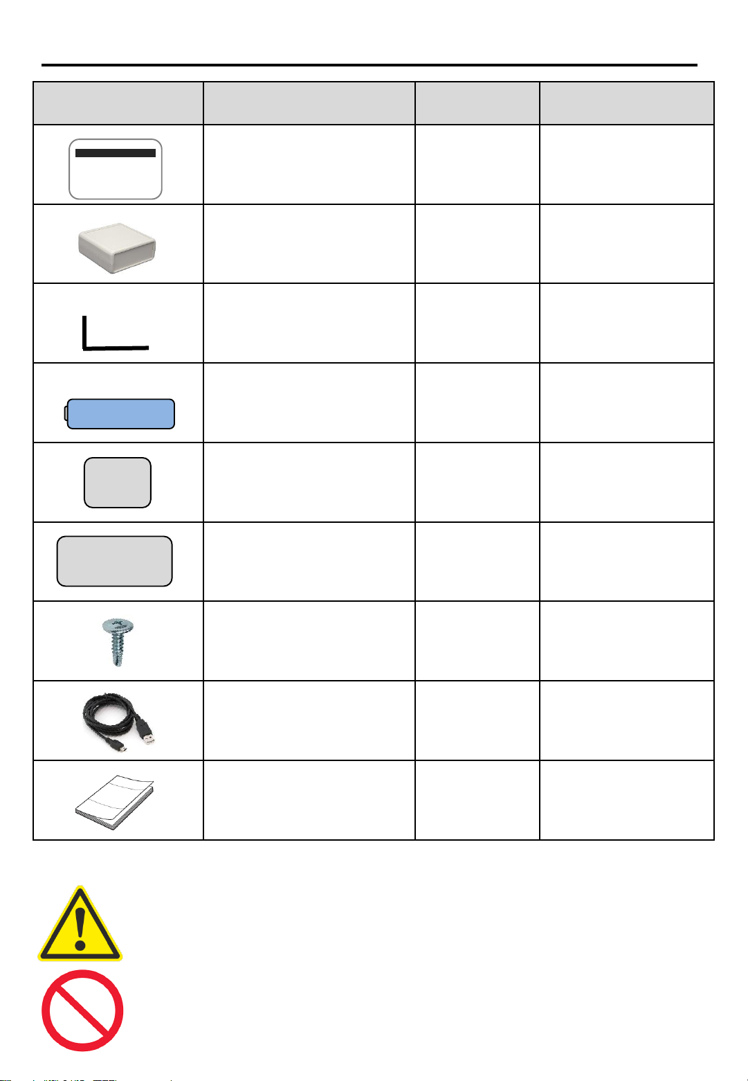
DELIVERY KIT
Depiction Element Name Quantity Description
Counters* 1 pair Footfall counters,
one pair: block Т
and block R
USB modem 1 USB modem for
collecting footfall
data
L-brackets 1 pair Brackets for fixing
the counters at the
entrance
Batteries 4 АА 1.5
V batteries: 2
per each counter
block
Adhesive pads, type 1 2 Pads for mounting
the counter on a
surface
Adhesive pads, type 2 2 Pads for mounting
the counter on a
surface
Screws 4
Screws for mounting
the counter on a
surface
USB cable 1 USB cable for data
transfer to the
modem
Quick Guide 1 Online manual
MEGACOUNT
* There is one pair of counters in the basic kit. Additional counter pairs can be supplied for
connecting to the USB modem through the radio channel
Up to 100 counters in the vicinity can be connected to one USB modem
** Use only АА 1.5 V batteries. Polarity must be correct when changing batteries
5

HOW IT WORKS
Operation of horizontal infrared OMEGA people counters is based on the principle of
crossing two infrared beams and determining the direction of movement for both In and
Out (bi-directional)
The main counting elements are two blocks —block T and block R: when directed at each
other, they create two beams between them. Each time the beams are crossed, block R
detects the fact of crossing and its direction, stores that data and later transfers it to the
Ethernet modem as pictured below
COUNTER
BLOCK R COUNTER
BLOCK T
Radio channel up to 200 m
2.4 Mhz carrier frequency
Infrared beams 990 nm
Direction of the people flow
Top view
USB radio modem USB
Server:
HTTP
HTTPS
FTP
sFTP (SSH)
EMAIL
Protocol:
OMEGA CLOUD
XML
JSON
TXT
Data transfer
6

GENERAL DESCRIPTION OF A PAIR OF COUNTERS
MEGACOUNT
COUNTER - BLOCK R
The main block R contains a beam-crossing analytics microprocessor and a radio-transmitting
element. The microprocessor stores all events of beams crossing and transfers them to the ETH-
modem via a radio channel with 2.4 MHz carrier frequency. Data that has not been transferred is
stored on the counter for 14 days. Each R-block must be connected with the ETH-modem —see
the manual. Infrared band 990 nm
Dimensions: 42 mm –height, 68 mm –length, 18 mm –width
Direction indicator
Bi-directional counting
BLUE
RED
Unidirectional counting
BLUE + RED
Photovoltaic cells
Built-in radio transmitter
MEGACOUNT
COUNTER - BLOCK T
Photovoltaic cells
The supporting T-block enables infrared lighting and contains a microprocessor and a chain of
photovoltaic cells that are needed for creating beams and for lighting objects. T-block is not
connected to the R-block and can be used by any R-block without being connected to it. Infrared
band 990 nm
Dimensions: 42 mm –height, 68 mm –length, 18 mm –width
7

COUNTER CHARACTERISTICS
•Protection from dust/water, IP 60
The device is intended to be installed inside where water cannot reach it. The sensor is
inside a dust-proof casing with IP 60 protection:
6 –No ingress of dust; complete protection against contact
0 –No protection against water
•Dimensions
People counter: 42х68х18 mm
Data-collecting ETH-modem: 66x66x28 mm
•Data export, server
OMEGA CLOUD
FTP
SFTP (SSH File Transfer Protocol)
HTTP
HTTPS
EMAIL
•Data export, protocol
OMEGA
XML
JSON
TXT
•Modem interface
USB through operating systems WINDOWS, LINUX, iOS
•Power supply
АА 1.5 V batteries: 2 per each counter block
Battery change is carried out by the user
Power consumption 60 µA
•Delivery kit
People counters - 2 blocks, R-T
USB modem - 1 pc
Adhesive pads - 4 pcs
L-brackets - 2 pcs
Screws - 4 pcs
USB cable - 1 pc
АА 1.5 V batteries - 4 pcs
•Operating time on a single battery set
Up to 1 year on one set of batteries, depending ondevice settings
•Distance between the modem and the counters. Radio channel
Counters can be up to 200m away from the modem, depending on radio broadcast and
obstacles 8
STEP 1.
INSTALLING THE SOFTWARE
OMEGA-USB software works as a service with connection through a shell.
Shell Service
Launches from the Desktop through
OMEGA-USB shortcut. One can set up
data export and configure counters
through this shell.After the shell is closed,
main service will continue operation
according to the settings
Launches automatically together
with OS start and receives data
from the counter and set data
export
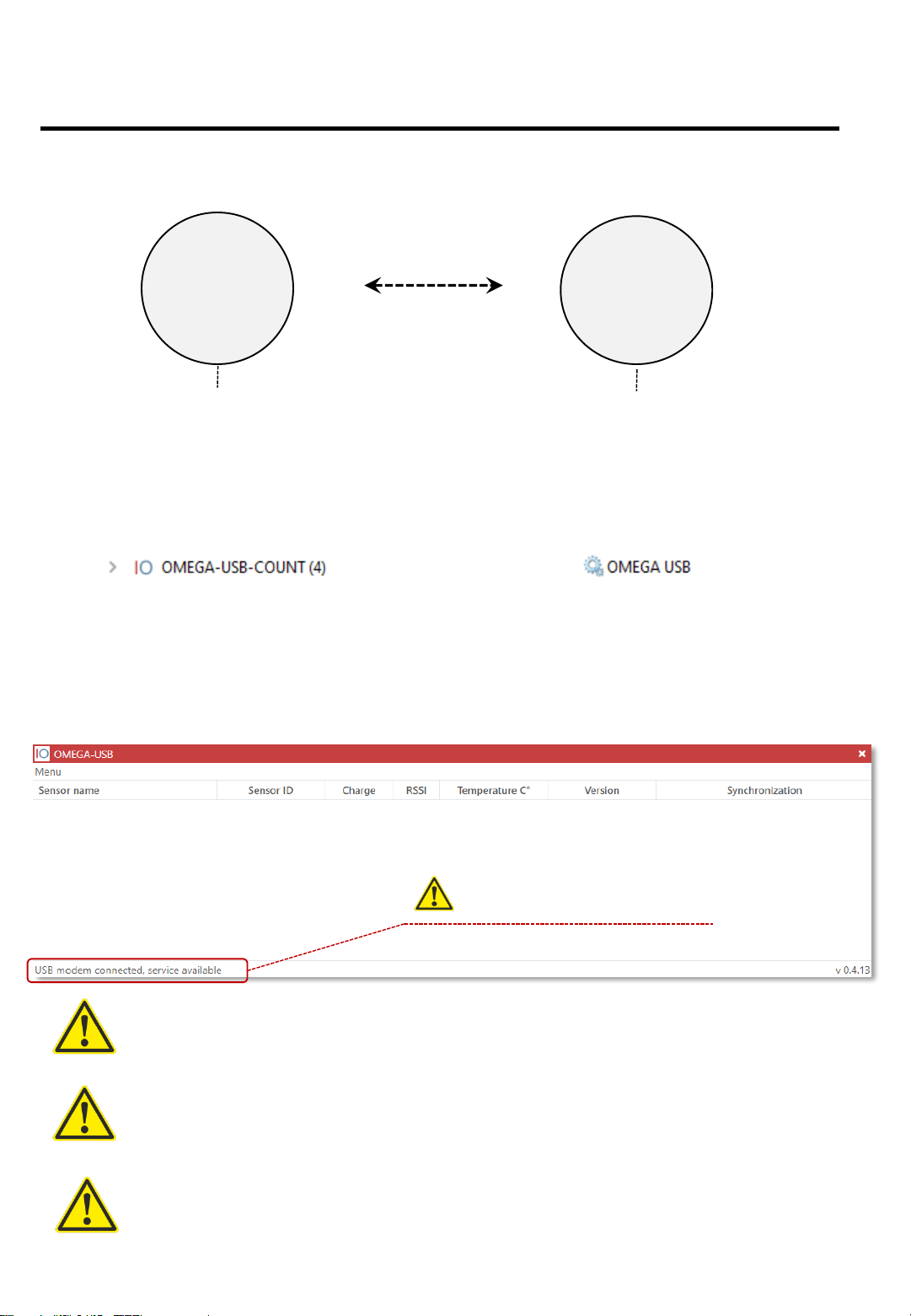
Installing the software
Install the software and launch the OMEGA-USB shortcut on the Desktop, connect the
USB modem to the PC and wait for modem drivers to install. If everything is done
correctly, the interface will look like this:
DEFAULT PASSWORD: 18318
To change the password, use the password changing option in Menu –Password
USB MODEM IS CONNECTED, SERVICE IS WORKING –
OBLIGATORY CONDITIONS FOR FURTHER CONFIGURATION
If the program says that service is not working, check anti-virus software and allow the program
there, then restart the service: Menu-Service reset
If the program says that the USB modem is not connected, check if the modem is connected and
the drivers are installed (they are installed automatically), allow the program in the anti-virus
software, then restart the service: Menu-Service reset
Obligatory requirement for further configuration and
counter connection
9

STEP 2.
INSTALLING BATTERIES INTO THE COUNTERS
TO OPEN THE CASING FOR INSTALLING OR CHANGING
BATTERIES, HOLD THE CASING SO THAT THE
PROTECTIVE BLACK SCREEN IS FACING UPWARDS AND
SLIDE DOWN ONE HALF OF THE CASING AS SHOWN ON
THE PICTURE
Slide this down and open the casing
Protective black screen
Opening the casing
Installing batteries in blocks R and T
Install batteries into holders with correct polarity as shown on the picture below
POLARITY MUST BE FOLLOWED CORRECTLY!
IF IT IS WRONG, DEVICE OVERHEATING AND LOSS OF
FUNCTION ARE POSSIBLE, WHICH ARE NOT COVERED BY
WARRANTY
If everything is installed correctly, the indicator on the counter will blink. If the indicator is not
lighting up, take out the batteries right away and check polarity
10
STEP 3.
CONNECTING THE COUNTER TO THE USB MODEM
Preparing the R-block for connection to the USB modem
Open the counter’s casing and press the button Service while the program is
scanning, as shown on the picture below
Press the button at the moment when the
program is scanning
This process is only done for the R-block
11
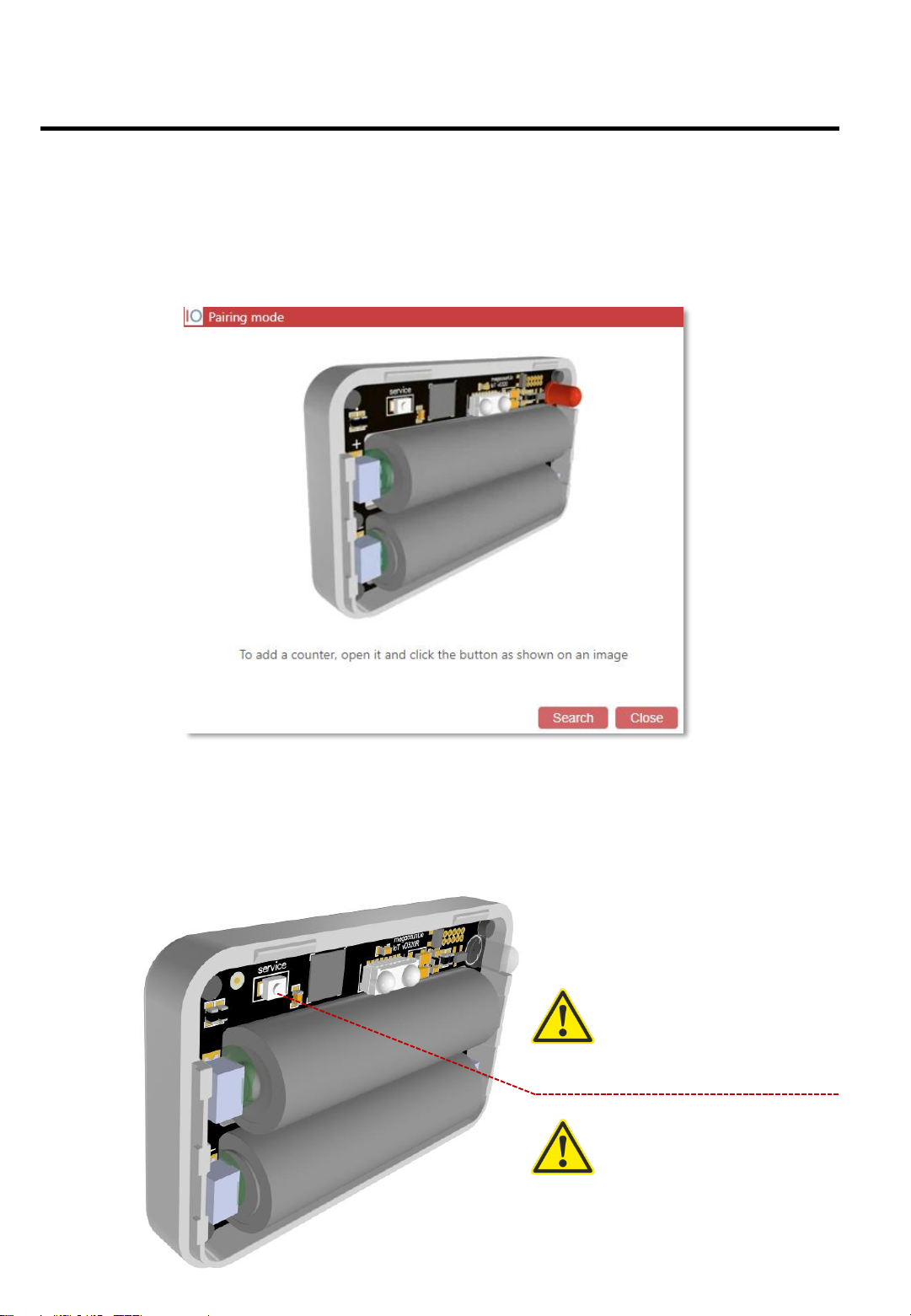
Software preparations
Launch OMEGA-USB control shell from the Desktop or through System tray and go to
Menu-Add counter.Awindow for connecting the modem with the counter will open.
Click the [SCAN] button in the program and press the [SERVICE] button on the R-
block while the program is scanning (see below)
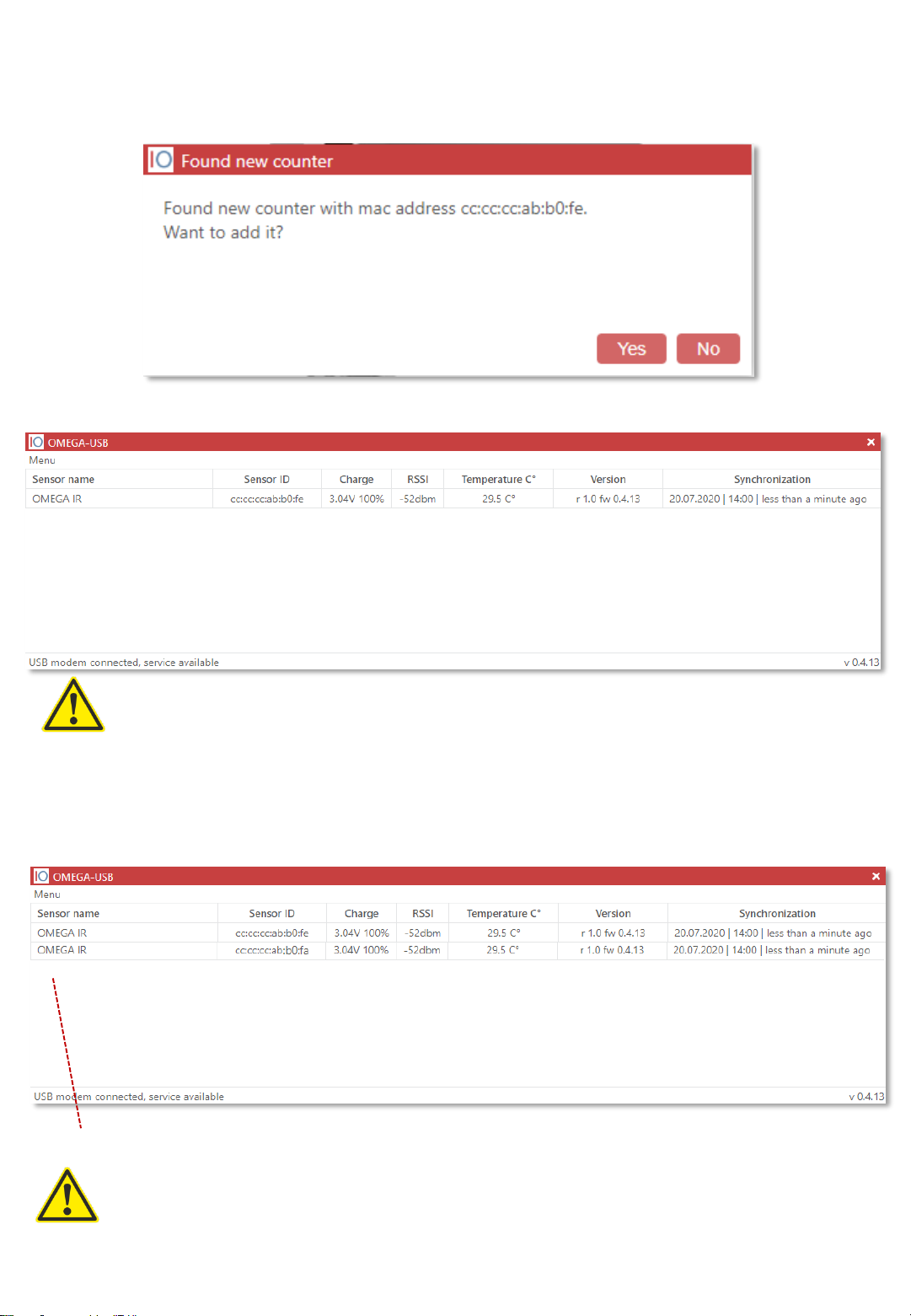
Connecting the counter and adding it to OMEGA-USB program
If all previous steps are done correctly, the program will show the found counter
and will suggest to add it. Click the [Yes] button
Counter that is found and connected to the USB modem:
Process of connecting to the modem is only necessary for the R-block, it is not needed for the T-
block!
Connecting additional counters and adding them to OMEGA-USB program
If there are additional pairs of counters, follow the same connection process (as described
before for the R-blocks) for the additional pairs and rename them in the program according to
their location
One entry indicates one pair of counters: R-block and T-block
Example:
One entrance with one pair (two blocks) –there will be one entry in the program
Two entrances with two pairs (four blocks) –there will be two entries in the program
12
Right entrance
Left entrance

STEP 4.
SETTING THE DISTANCE BETWEEN THE COUNTERS
After the R-block is added to the program, it is necessary to configure the T-block by
setting the correct distance between the blocks
Open the casing of the T-block and set the distance on it by moving the correct
switch to the right as shown on the pictures below
Example for installation with a 2m distance
Example for installation with a 3m distance
13
STEP 5.
MOUNTING THE COUNTERS TO THE SUFRFACE
After the R-block is connected to the ETH-modem and the entrance width (distance
between blocks) is set on the T-block, the counters can be mounted at the entrance
with brackets or adhesive pads. Check detection after mounting
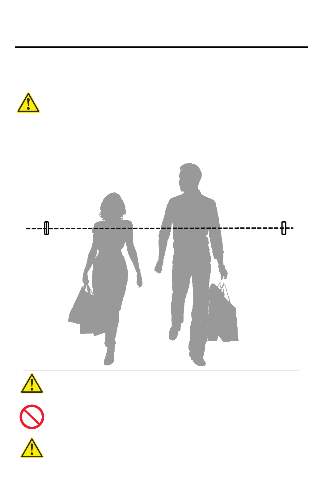
Installation height
Optimal installation height is so that the counters are on shoulder level of a person
with the height that is slightly lower than average. It should be as displayed on the
picture below
Main recommendation when mounting counters (blocks) –fix the counters so that the R-block is
facing the ETH-modem
When mounting the counters, mind the door handles: they should not be in the
counters’ operating field
When mounting the counters, mind the daylight: it is not recommended to install
counters under direct sunlight at any time of the day. It is recommended to install the
counters further inside if possible
After the counters are fixed, be sure to walk by them a few times to check detection:
when someone enters, the R-block will be blinking with blue or red. Walk 20-30 times
observing the indicators and making sure the counters work properly
14
STEP 6.
COUNTER CONFIGURATION
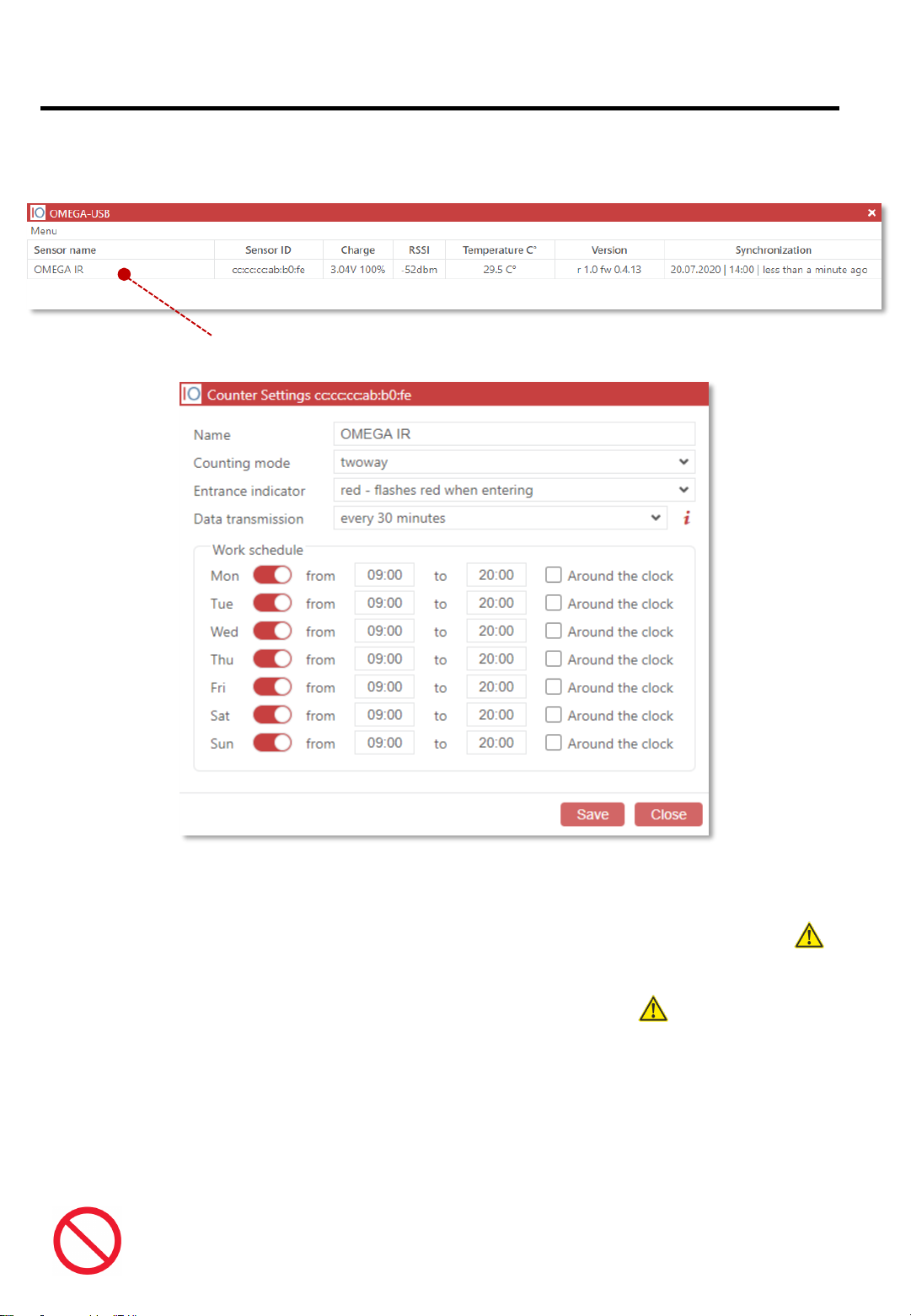
To configure the counter, double click on the name of the counter or click [Counter
configuration] in the context menu
Double-click to open counter settings panel:
[Name] Counter ID –for example, Left entrance, Main entrance, Right entrance, etc.
[Counting mode] Bi-directional –sensor counts for both In and Out and the indicator lights
up with blue or red depending on the direction. Unidirectional –sensor counts only in one
direction and logically divides the data by two, both indicators blink simultaneously; no
need to additionally divide end values by two
[Entrance indicator] If the indicator is red when someone enters –put in RED, if the
indicator is blue when someone enters –put in BLUE. Important!
[Data transmission] Optimal interval is every 5-8 hours. The bigger the interval, the more
battery is saved
[Operating time] The counter is set up to work around the clock by default. It is necessary
to set up proper operating time and exclude non-operating days and time
Operating time of the counter and the [Data transmission] parameter directly affect
battery life. Set up correct operating and non-operating days and time and a
reasonable data transfer interval. Important!!! 15
STEP 7.
DATA EXPORT
When the counters are mounted and are counting, set up data export in the OMEGA-USB
program [ Menu –Data export –Create export ]
4 server types are available for data export:
OMEGA CLOUD –connecting the counter to cloud analytics with the possibility to view data
via any browser and smartphone
HTTP(S) –packet data transfer in JSON or XML format to a server that supports TLS
encryption
FTP/sFTP-SSH –file data transfer in JSON, XML, TXT formats to a server that supports
safe sFTP
EMAIL –data transfer in JSON or XML format to email
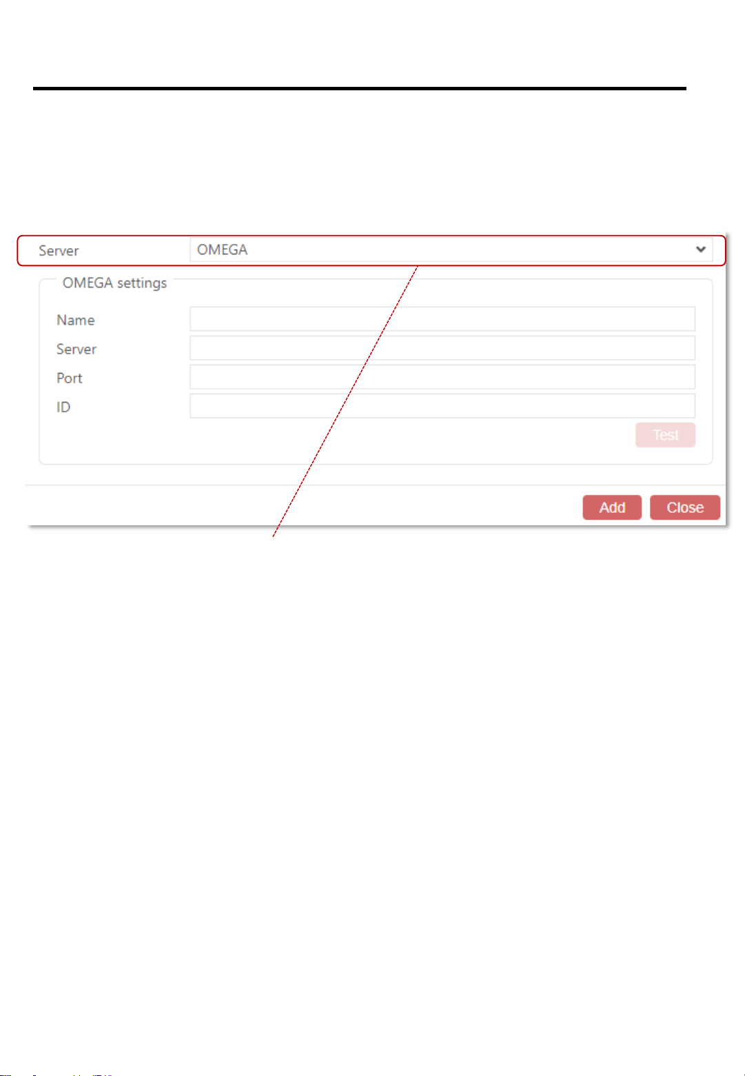
This will open the panel with server types for data export:
16
STEP 7
7.1 SETTING UP OMEGA CLOUD ANALYTICS
To connect to OMEGA analytics, open OMEGA-USB interface and then tabs
[ Menu –Data export –Create an export –OMEGA server type ]
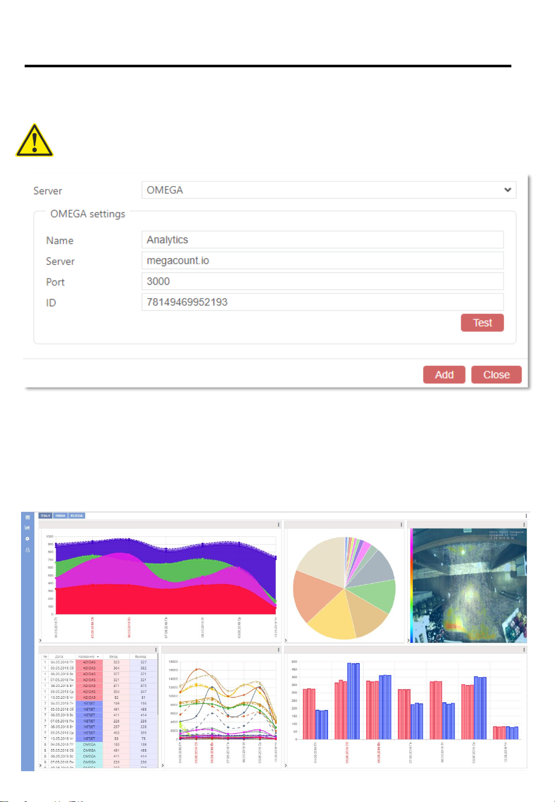
TO GET CONNECTED TO WEB-ANALYTICS, SEND A
REQUEST TO info@megacount.io
When you are connected to the analytics program, it will be possible to view data with a
browser on any PC, laptop or smartphone
[Name] Any name/ID for the data export, e.g. Analytics, My data export, etc.
[Server] Will be provided with the response to your request
[Port] Will be provided with the response to your request
[ID]Will be provided with the response to your request
17

STEP 7
7.2 SETTING HTTP(S) DATA TRANSFER
To set up data transfer to the server, open OMEGA-USB interface and then tabs
[ Menu –Data export –Create an export –HTTP(S) server type ]
DATA IS TRANSFERRED IN PACKETS! TO RECEIVE THE
NEXT PACKET, THE SERVER MUST REPONSE WITH THE
CODE 202 OR AN “ACCEPTED” TEXT MESSAGE — ONLY
THEN WILL THE PROGRAM SEND THE NEXT DATA PACKET
HTTP(S) settings:
[Name] Any name/ID for the data export, e.g. Analytics, My data export, etc.
[Protocol] http or https with TLS encryption support
[Server] Server address for receiving packets; supports DNS
[Port] Port address of the server to which the data will be pushed
[URI] Receiving script resource ID
Data export format:
[JSON] transferred data will be in JSON format
[XML] transferred data will be in XML format
18

STEP 7
7.3 SETTING EMAIL DATA TRANSFER
To set up data transfer to an EMAIL server, open OMEGA-USB interface and then tabs
[ Menu –Data export –Create an export –EMAIL server type ]
EMAIL settings:
[Name] Any name/ID for the data export, e.g. Analytics, My data export, etc.
[File name] Compound file name format. $ID# and $CD# tags are obligatory
[Port] Port address of the server to which the data will be pushed
[URI] Receiving script resource ID
[Server], [Port], [TLS], [Authentication], [Login], [Password] Client EMAIL settings
[Test] Put in any email address and click Test; if everything is done correctly, a test letter will
be received on that email address
Sending time:
[Every day] Time settings for data export
[Interval] Sending interval and time range settings
[Port] Port address of the server to which the data will be pushed
Add receiving email addresses and set letter contents
19
STEP 7
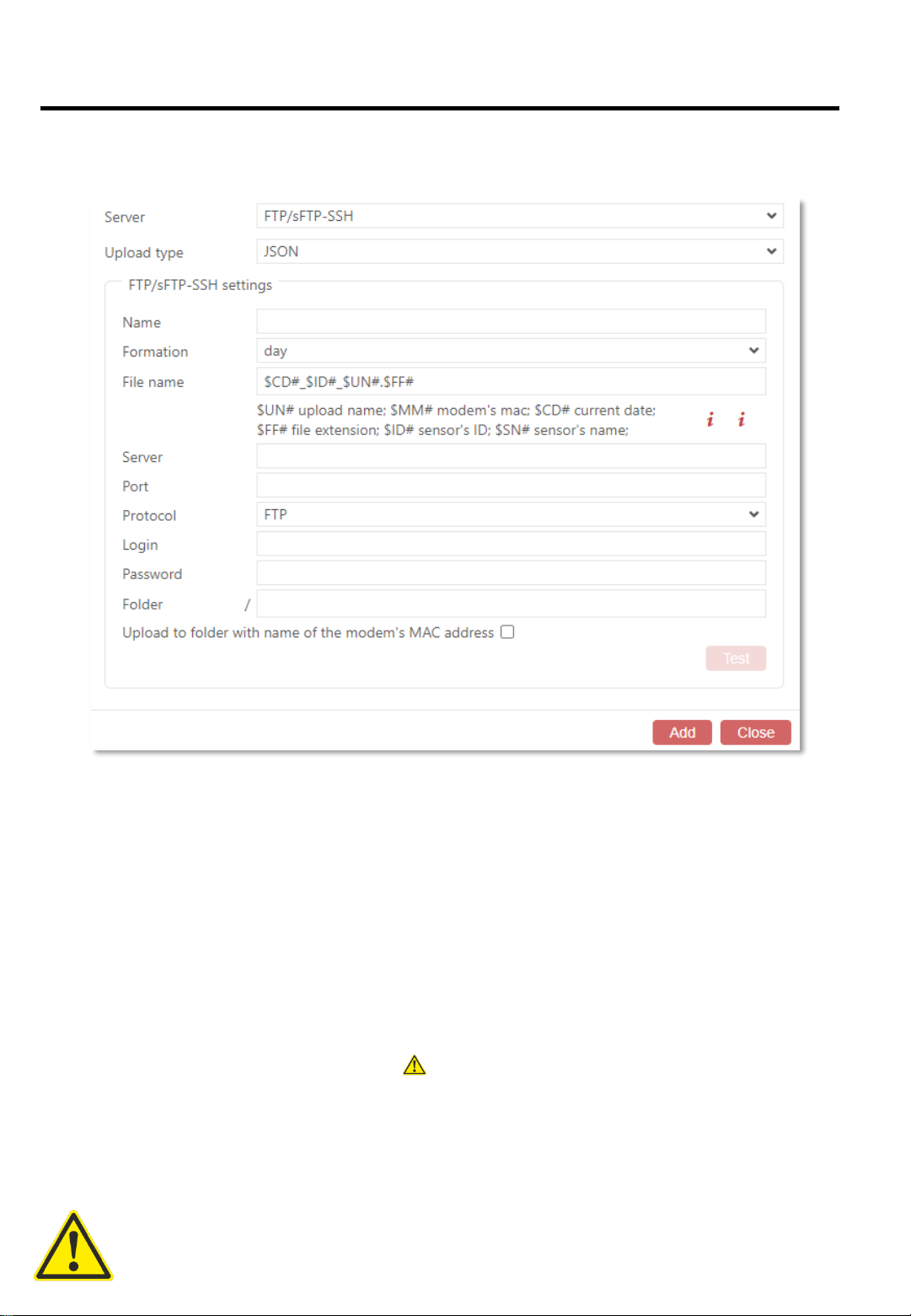
7.4 SETTING FTP/sFTP-SSH DATA TRANSFER
To set up data transfer to the server, open OMEGA-USB interface and then tabs
[ Menu –Data export –Create an export –FTP/sFTP-SSH server type ]
FTP/sFTP-SSH settings:
[Name] Any name/ID for the data export, e.g. Analytics, My data export, etc.
[Formation]
Day –there will be one single file created on FTP; it will contain all the data for the whole day
(one day –one file)
Accumulating day –there will be a new file created on FTP each time with a growing end
value (one day –many files)
[File name] Compound file name format. $ID# and $CD# tags are obligatory
[Port] Port address of the server to which the data will be pushed
[URI] Receiving script resource ID
[Server], [Port], [Protocol], [Login], [Password], [Directory] FTP Settings
[Upload to folder with name of the modem’s MAC address] The program will create a
folder with the modem’s MAC-address on the FTP server and will export the datathere
Data export format :
[JSON] transferred data will be in JSON format
[XML] transferred data will be in XML format
[TXT] transferred data will be in TXT format
Data is exported each time any of the counters is connected to the ETH-modem via the
radio channel 20
Table of contents
Other MegaCount Cash Counter manuals


