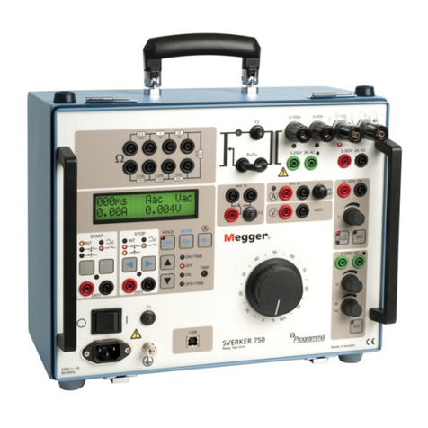
Users of this equipment and/or their employers are reminded that National
Health and Safety Legislation requires them to carry out valid risk assessments
of all electrical work so as to identify potential sources of electrical danger and
risk of electrical injury such as inadvertent short circuits. Where the
assessments show that the risk is significant then the use of fused test leads
may be appropriate.
Symbols used on the instrument:
GCaution: refer to accompanying notes
tEquipment protected throughout by Double Insulation
(Class II)
cEquipment complies with relevant EU Directives
Equipment complies with ‘C tick’ requirements
Do not dispose of in the normal waste stream
Maximum input voltage 600 V rms
Application
BS EN 61010 defines measurement categories from I to IV relating transient
over voltages and the location within the electrical installation. This
instrument is designed for use at Category III (Building
installation/distribution board level) up to 600 V (maximum) rms to earth and
600 V (maximum) rms between terminals. It may also be used at Category IV
(Primary supply level) on 300 V rms phase to earth systems.
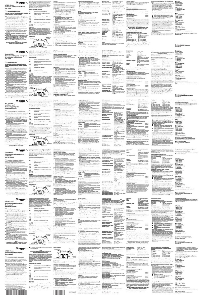
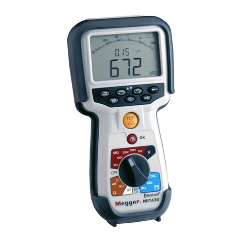
Display layout
Accuracy (at 20° C) ±3%, ±2 digits (or 30% of reading
200 kΩto 10 MΩ)
Continuity ranges
Measuring Range: 0,01 Ω-100 Ω(0 -50 Ωon analogue
scale)
Open Circuit Voltage: 5 V ±1V
Short Circuit Current: 205 mA, ± 5 mA (0 to 10 Ω)
(>20 mA up to 100 Ω)
Accuracy (at 20° C): ±3% ±2 digits
Null Offset Adjust: 0 – 9 Ω
Continuity Buzzer: Operates at < 5 ΩResponse time
<20 ms
Default voltmeter: all test modes except off
Test inhibit: >50 V
AutoPower Down: Operates after 10 minutes if left in
standby mode.
Environmental
Operating Range: -10°C to +55°C
Operating Humidity: 93% R.H. at +40°C max.
Storage Range: -25°Cto +65°C
Dimensions: 195 mm x 98 mm x 40 mm
Weight: 550 gms
Battery: 6 x 1,5 V cells IEC LR6 type (AA
alkaine) or NiMH rechargeable
Battery life: 3000 consecutive tests (5 sec/test)
on any test using 2Ah batteries
Fuses
Terminals: 500 mA (F) 600 V, 32 x 6 ceramic HBC
50 kA minimum
Safety
Meets the requirements of BS EN61010-1, Cat III 600 V phase to earth. Refer to
safety warnings supplied.
Automatic discharge
After an insulation test, the circuit under test will be discharged automatically.
Any voltage present will be indicated on the display so that the discharge can
be monitored.
EMC
In accordance with IEC 61326 including amendment No.1
Included accessories
Test lead set (red and black) with crocodile clips 6220-779
Hard carry case 5410-346
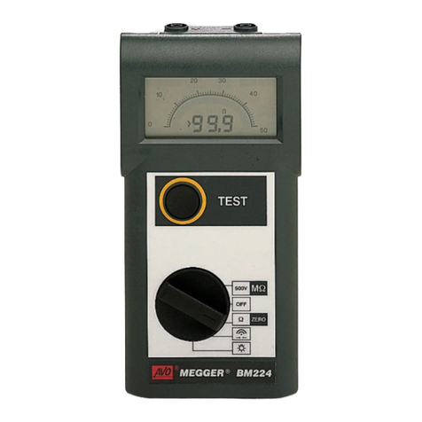
M
MIT200 Series
Insulation and Continuity Testers
User guide
Operation
All circuits must be isolated before an insulation or continuity test.
Automatic Voltage detection
The instrument will automatically display voltage between 25 V and 600 Vac
or dc when connected to the circuit under test.
Remove the source of any voltage before continuing to test.
Test lead check
1. Before each use of the instrument, inspect the test leads, prods and
crocodile clips to confirm that their condition is good, with no damaged or
broken insulation.
2. Check continuity of the test leads by firmly shorting the leads together and
read the test lead resistance measurement directly from the display.
Backlight operation
1. Turn the instrument backlight on by selecting the position. Backlight
stays on for 1 minute.
2. When the backlight is activated, select the desired test position.
3. Change range or press [TEST] to re-initialise backlight for another minute.
Test lead null
To remove test lead resistance before continuity tests:
1. Switch the instrument to [Ω]
2. Short test leads together, wait for a stable reading and press the test button
on the instrument. The display should read 0.00 Ωand display the [z]
symbol.
Lead null value is automatically stored until reset.
To remove, press the TEST button again with leads open circuit.
Continuity Measurement [Ω]
1. Set range switch to [Ω].
2. Connect the red and black test leads to the circuit to be tested. The
instrument will automatically display continuity resistance when connected
(up to 99.9 Ω).
NOTE: If “>100.0 Ω“ is displayed the resistance of the circuit is over-range.
Continuity Buzzer [ ]
1. Set the instrument to [ ] range.
2. Connect the test leads to the circuit to be tested.
3. The buzzer will sound automatically when a circuit is made
(<5Ω)
4. If a circuit voltage >2 V is detected the test will be inhibited.
Insulation testing [ MΩ] all instruments
1. Set range switch to [250 V], [500 V] or [1 kV] as available.
2. Press and hold down the TEST button to start test. The display will settle,
and show the insulation test resistance in MΩ.
3. If a circuit voltage of >25 V is detected the instrument will give a warning
Beep but allow testing to continue.
If a circuit voltage >50 V is detected, further testing will be prevented.
Warning:
After testing ensure the display returns to Zero (circuit is discharged) before
removing test leads.
Error messages:
>100.0 ΩContinuity over-range
<0.01 M ΩInsulation test result is under-range
>1000 M ΩInsulation test result is over-range
UNC Uncalibrated
E17 Instrument not configured to a specific type.
Battery replacement
Low battery voltage is indicated by the symbol in the display. To
maintain performance the batteries should be replaced at this point.
Uses 6 x 1.5 V AA (LR6) alkaline dry cells or NiMH rechargeable batteries.
To replace batteries switch off instrument and disconnect test leads from the
circuit under test.
Remove the rear battery cover and replace the batteries. Do not mix old and
new batteries.
Warning: OBSERVE CORRECT POLARITY. Incorrect battery polarity could
cause batteries to leak and damage the instrument.
Fuse replacement
A blown fuse is indicated by the symbol in the display.
To replace the fuse remove battery cover and replace fuse with type: 500 mA
(F) HBC 50 kA 600 V.
Cleaning: Wipe disconnected instrument with a clean cloth dampened with
soapy water or Isopropyl Alcohol (IPA).
Specification
Insulation ranges
Test voltage accuracy: -0% +25% over full operating
temperature
Nominal Test Voltage: 1000 V, 500 V, 250 V (d.c.)
Measuring Range: 10 kΩ- 999 MΩon all ranges
Short Circuit Current: 2 mA -1 mA +0 mA
Test Current on Load: 1 mA at min. pass values of
insulation (as specified in BS 7671,
EN61557, HD 384 and IEC 364)
GSafety Warnings and Precautions
These must be read and understood before the instrument is
used. They must be observed during use.
■The circuit under test must be switched off, de-energised and isolated
before test connections are made when carrying out insulation and
continuity tests.
■Circuit connections and exposed metalwork of an installation or equipment
under test must not be touched. Remember remote conductors may be
charged to the test voltage.
■The live circuit warning and automatic discharge are additional safety
features which may fail and therefore safe working
procedures/practices must be observed.
■The voltage function will only work if the instrument is functional and
switched on.
■After insulation tests, capacitive circuits must be allowed to discharge
before disconnecting test leads.
■The instrument, test-leads, probes and crocodile clips must be in good
order, clean and with no broken or cracked insulation.
■Ensure that hands remain behind guards of probes/clips when testing.
■National Safety Authorities may recommend the use of fused test leads
when measuring voltage on high-energy systems.
■Replacement fuses must be of the correct type and rating. to observe this
will result in a safety hazard.
■The rear cover must be in place whilst conducting tests.
NOTE
THE INSTRUMENT MUST ONLY BE USED BY SUITABLY TRAINED
AND COMPETENT PERSONS.
Optional accessories
2wire fused probe and clip set 6220-787
Rubber holster (Boot) 5410-346
Repair and Warranty
The instrument contains static sensitive devices, and care must be taken in
handling the printed circuit board. If an instrument’s protection has been
impaired it should not be used, but sent for repair by suitably trained and
qualified personnel. The protection is likely to be impaired if for example, it
shows visible damage, fails to perform the intended measurements, has been
subjected to prolonged storage under unfavourable conditions, or has been
subjected to severe transport stresses.
NEW INSTRUMENTS ARE GUARANTEED FOR 3 YEARS FROM THE
DATE OF PURCHASE BY THE USER.
Note: Any unauthorized prior repair or adjustment will automatically
invalidate the Warranty.
CALIBRATION, REPAIR AND SPARE PARTS
For service requirements for Megger Instruments contact:
Megger Limited or Megger
Archcliffe Road Valley Forge Corporate Centre
Dover 2621 Van Buren Avenue
Kent CT17 9EN Norristown PA 19403
England. U.S.A.
Tel: +44 (0) 1304 502 243 Tel: +1 610 676 8579
Fax: +44 (0) 1304 207 342 Fax: +1 610 676 8625
Megger operate fully traceable calibration and repair facilities, ensuring your
instrument continues to provide the high standard of performance and
workmanship you expect. These facilities are complemented by a worldwide
network of approved repair and calibration companies to offer excellent in-
service care for your Megger products.
Returning your product to Megger - UK and USA service centres
1. When an instrument requires recalibration, or in the event of a repair being
necessary, a Returns Authorisation (RA) number must first be obtained
from one of the addresses shown above. You will be asked to provide the
following information to enable the Service Department to prepare in
advance for receipt of your instrument, and to provide the best possible
service to you.
■Model, e.g. MIT200.
■Serial number, to be found on the underside of the case or on
the calibration certificate (e.g. 6111-357/050305/1234)
■Reason for return, e.g. calibration required, or repair.
■Details of the fault if the instrument is to be repaired.
2. Make a note of the RA number. A returns label can be emailed or faxed to
you if you wish.
f
Analogue arc
display
Battery level
Digital display
Lead null indicator
Fuse blown
G>600V

