Megmeet MTC-04-NT User manual

1
MTC-04-NT Thermostat User Manual
Version V1.0
Archive time 2012.7

2
Shenzhen megmeet control technology co., ltd. provides customers with a full range of technical
support, users can contact with the nearest agents or technical service center of Shenzhen
megmeet control technology co., ltd., or directly with the headquarters of the company.
All rights reserved. Contents are subject to change without prior notice.
Shenzhen megmeet control technology co., ltd.
Add:5th Floor,Block B Unisplendour Information Harbor, Langshan Road, Shenzhen
Tel:400-666-2163 ,(86)0755-86600500
Fax:(+86)0755-86600999
Code:518067
Web:www.megmeet.com

3
Prompt
Before starting to use, please read the instructions and precautions carefully to reduce the
occurrence of accidents. The personnel responsible for the installation and operation of the
product must receive strict training, comply with the safety standards of the relevant industry,
strictly comply with the notes and special safety instructions of the relevant equipment provided
in this manual, and carry out the operation of the equipment according to the correct operation
method.
Model Description
TT:Indicates transistor temperature
control output
Input method
N: No CT (Current test) Input
The number of temperature channels
collected by the module
Thermostat
Megmeet
T
M
TC
04
-
-
N

4
1.Product Introduction
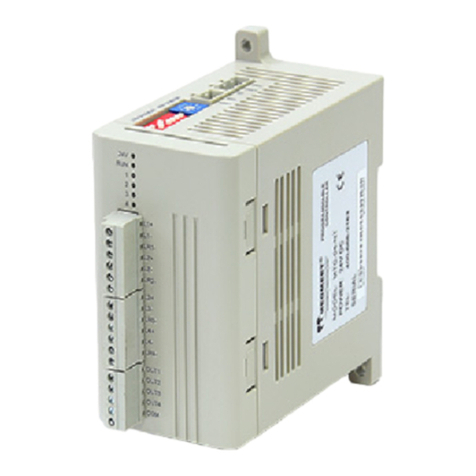
MTC-04-NT temperature controller is a multi - channel high precision temperature control
product developed by megmeet, suitable for various occasions of temperature control. Its
main features are compatible with thermocouple and thermal resistance, high precision
temperature measurement, rich functions, easy to use. This chapter introduces the
appearance structure, installation size, parts, technical parameters, buffer and
accessories of MTC-04-NT.
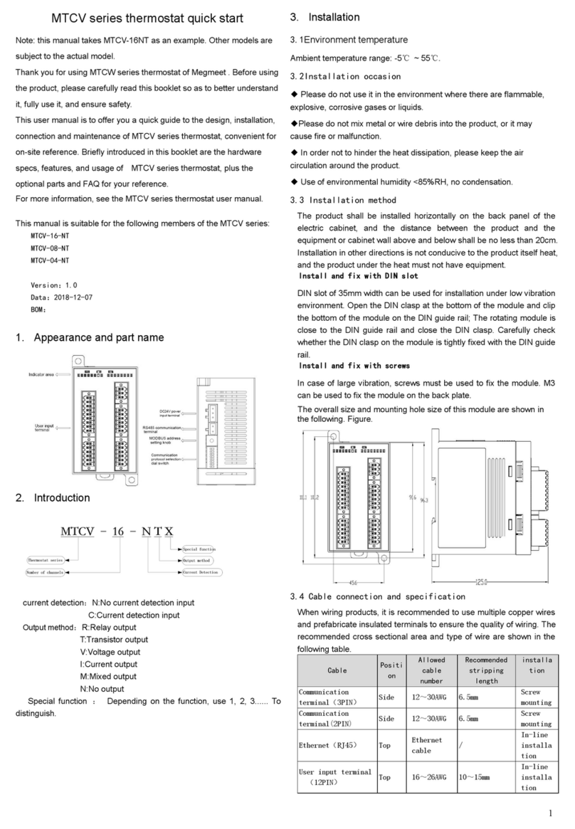
1.1Appearance structure and installation dimensions
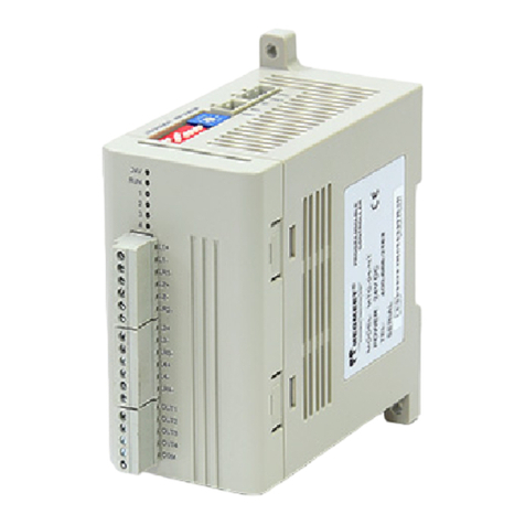
The user terminal of the MTC-04-NT thermostat is shown in figure 1-1
Top view Side view
Figure 1-1 MTC-04-NT outline structure diagram
The mounting dimensions of MTC-04-NT are shown in figure 1-2
Figure 1-2 MTC-04-NT installation dimensions (unit: mm)
1.2 Terminal introduction

5
MTC-04-NT user terminal is shown in figure 1-3
Figure 1-3 MTC-04-NT user terminal diagram
The definition of MTC-04-NT user terminal is shown in table 1-1
Table 1-1 MTC-04-NT terminal definitions
1.3 Light description
The indicator description is shown in Table 1-2
Table 1-2 indicator description
Name
Status
Definition
24V
ON
24V power on
OFF
24V power off
RUN
Flash quickly(10Hz~15Hz)
Normal
Flash slowly(0.5Hz~1Hz)
There is an error. See
BFM#735 for the error status
Mark
Definition
24V-
Power supply 24V positive
24V+
Power supply 24V negative
Ground
485-
RS485 negative terminal
485+
RS485 positive terminal
L1+~L4+
Channel 1 to 4 are positive for thermocouple (thermal resistance) signal
input
L1-~L4-
Channel 1 to 4 are negative for thermocouple (thermal resistance) signal
input
LR1-~LR4-
Channel 1 ~ 4 are negative for thermal resistance signal input
OUT1~OUT4
Channel 1 ~ 4 output control terminal
COM0
OUT1 ~OUT4 output common ground

6
information
LED1~4(OUT1~OUT4)
ON
The corresponding channel
output is ON
OFF
The corresponding channel
output is OFF
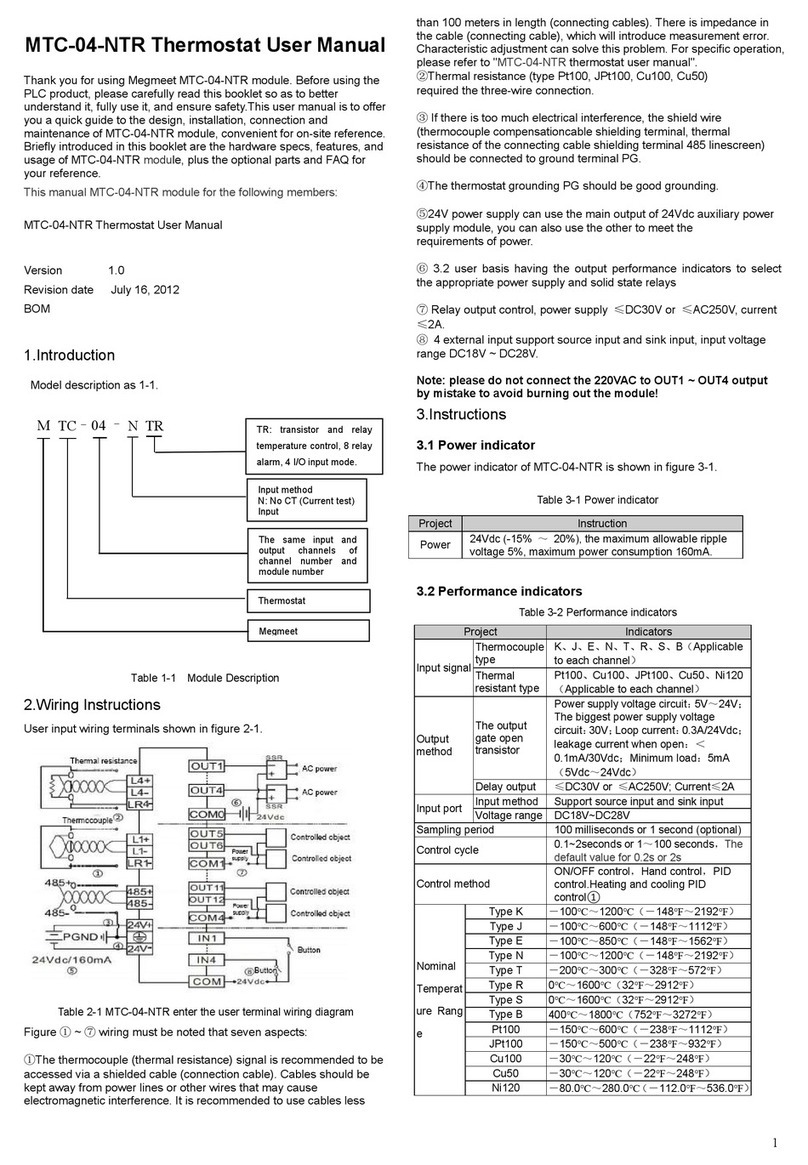
1.4 Technical parameter
1.4.1 Power indicator
The power specifications of MTC-04-NT are shown in Table 1-3.
Table 1-3 Power indicator
Project
Instruction
Power
24Vdc (-15% ~20%), the maximum allowable ripple voltage
5%, maximum power consumption 100mA.
1.4.2 Performance indicators
The performance indicators of MTC-04-NT are shown in table 1-4
Table 1-4 Performance indicators
Item
Indicators
Input
signal
Thermocouple type
K、J、E、N、T、R、S、B
Thermal resistance
type
Pt100、Cu100、JPt100、Cu50、Ni120
Output
method
Open gate transistor
output
Power supply voltage circuit:5V~24V;The maximum
power supply voltage circuit:30V;loop current:
0.3A/24Vdc;Leakage current when open:<
0.1mA/30Vdc;Minimum load:5mA(5Vdc~24Vdc)
Sampling cycle
100ms or 1s(optional)
Control cycle
0.1~10s or 1~100s,default 0.2s or 2s.Determined by
the characteristics of the temperature control object
Control method
Manual control,ON/OFF control,PID control,Heat and
cool PID control
Rate
temperat
ure range
Type K
-100℃~1200℃(-148℉~2192℉)
Type J
-100℃~1200℃(-148℉~2192℉)
Type E
-100℃~850℃(-148℉~1562℉)
Type N
-100℃~1200℃(-148℉~2192℉)
Type T
-200℃~300℃(-328℉~572℉)
Type R
0℃~1600℃(32℉~2912℉)
Type S
0℃~1600℃(32℉~2912℉)
Type B
400℃~1800℃(752℉~3272℉)
Pt100
-150℃~600℃(-238℉~1112℉)
JPt100
-150℃~500℃(-238℉~932℉)
Cu100
-30℃~120℃(-22℉~248℉)
Cu50
-30℃~120℃(-22℉~248℉)

7
Ni120
-80.0℃~280.0℃(-112.0℉~536.0℉)
Accuracy
Thermocouple
Input range±0.3%,Ambient temperature
compensation error ≤2℃
Thermal resistance
Input range±0.5%
Isolation
The sampling channel is isolated from the power supply,
the sampling channel is isolated from the output, and
no isolation between channels
Note: 1. Through the appropriate input type selection Settings, two kinds of data can be
obtained: ℃and ℉.
2. Standard for thermocouple and thermal resistance:
K, J, E, N, T, R, S, BIEC 60584-1-1995
PT100 IEC60751 - AM2-1995
JPT100 JIS C1604-1997
Cu100, Cu50 JJG 229-1998
1.5 Buffer description
MTC-04-NT and the main module exchange information through the buffer (BFM), using Modbus
or MCbus. The cache that reads and writes properties can use MODBUS or MCBUS instructions to
write and read the contents of any cell in the BFM region. If the reserved cell is read, it will get a
value of 0. Save mark as Y represents the use of parameter save function, can be written to flash,
mark as N means can not be written to flash. The content of the BFM unit is as follows:
1. Channel operation monitoring.
2. Channel feature setting.
3. Control function setting.
4. Multi-step function setting.
5. Alarm function setting.
6. Litre/temperature limit setting.
7. Save and set BFM parameters.
8. The other.
1.5.1 Channel operation monitoring
The channel operation monitoring content of the buffer zone (BFM) of MTC-04-NT is shown in
Table 1-5
Table 1-5 MTC-04-NT buffer (BFM) channel operation monitoring
BFM
Contents
Remarks
natur
e
Save
CH1
CH2
CH3
CH4
#701
#702
#703
#704
Measured value(PV)
*1
Units: 0.1 ℃and 0.1
℉
R
N
#709
#710
#711
#712
Heat side control
output (MV) * 2
The default value:
0.0% (percentage
show)
R
N
#717
#718
#719
#720
More paragraphs of
the currently
executing period
control * 3
Default value: 0.0%
(expressed as a
percentage)
R
N
#725
#726
#727
#728
Multi-step control
current execution
Default value:0
Range:0~8
R
N

8
BFM
Contents
Remarks
natur
e
Save
CH1
CH2
CH3
CH4
segment * 3
#733
Output state of
refrigeration end *4
Default value:0
R
N
#734
Input port status*5
Default value:0
R
N
#735
Error status word * 6
Default value:0
R
N
#736
Set value range error
address*7
0:normal
Other values: setting
the wrong BFM
address
R
N
#737
Cold junction
temperature*8
Default value:0
R
N
#738
#739
#740
#741
Work status word * 9
Default value:0
R
N
* 1. #701 ~ #704:The measured value of channel 1 to channel 4. The unit is determined according
to the input type (#901 ~ #904). When the mode is Celsius, the unit is 0.1℃; when the mode is
Fahrenheit, the unit is 0.1℉.
* 2. #709 ~ #712:Heating side control output value MV; #717 ~ #720: cooling hot side control
output value MV; The control output value of the channel obtained by the control algorithm.
* 3. #725 ~ #728: Each channel Multi-step setting executes the current segment. The segment
number being executed when multiple segment Settings are displayed. 0: indicates that the
execution state is not set in multiple segments or that multiple segments are completed.
* 4. #733: Output status of refrigeration end. Bit0 corresponds to the output state of the
refrigeration end of channel 1, Bit1 corresponds to the output state of the refrigeration end of
channel 2, and so on. When is 1, the output of the refrigeration end is effective; when is 0, the
output of the refrigeration end is invalid.
* 5. The failure status information of #735 is shown in table 1-6
Table 1-6 status information for BFM#735
A state of BFM#735
ON(1)
OFF(0)
b0:Error
When b1 ~ b15 any error occurs, this flag is 1
(b1 ~ b2 in any one of 1, stop all channel AD
converter)
Correct
b1:Save
-
-
b2:Hardware fault
AD converter or other hardware failure
Hardware normal
b3:Set value backup error
When the interference and the MTC due to an
internal error occurs, the flag will change
to 1. Then if you turn the power off, still
not be clear error, please contact the sales
agent or our
Data backup normal
b4:The cold end
temperature compensation
error
b5:AD transform digital
range errors
AD transform digital output value is less than -1
or greater than 4096, the flag is 1
Digital output value is
normal
b6:Set data recovery error
When the interference and the MTC due to an
internal error, if error reading backup data, the
flag is 1
-

9
A state of BFM#735
ON(1)
OFF(0)
b7:Save
-
-
b8~b15:Broken
accidentally detection (only
support thermocouple)
1 ~ 4 channel thermocouple broken
accidentally, the flag is 1
No broken
accidentally wrong
channel
* 6. #736: error address setting value range. Incorrect BFM area code is displayed.
* 7. #737: reflects the current cold end temperature.
* 8. #738 ~ #741: status word for each channel. Shows the error state and control state of each
channel, #738 corresponds to channel 1, #739 corresponds to channel 2, and so on. See table 1-7
for specific information.
Table 1-7 Error status and control of the state of each channel
Bite
Definition
ON(1)
OFF(0)
b0~b3
Alarm 1 ~ 4 state
Alarm
No alarn
b4
Sign of Initialization
complete
Initialization complete
Initialization
unfinished
b5
Auto-tuning state
Auto-tuning state
Status of no
auto-tuning
b6
Control state
Control state
uncontrolled state
b7
Control completion status
The temperature reaches setting and
in a stable state
Incomplete control
b8~b15
Save
-
-
1.5.2 Channel characteristics set
MTC-04-NT buffer (BFM) channel characteristics set as table1-8
Table 1-8 MTC-04-NT buffer (BFM) channel characteristics set
BFM
Content
Remarks
Natu
re
Sav
e
CH1
CH2
CH3
CH4
#200
Restore factory setting*1
Default value:0
R/W
N
#201
Change Settings allowed*2
Default value:1,Allows to change
0:Not Allowed To Change
R/W
N
#801
#802
#803
#804
Digital filter set of one step
Default value:0
Range:0~100 (Seconds)
R/W
Y
#809
#810
#811
#812
D0*3
Default value:0
R/W
Y
#817
#818
#819
#820
D1*3
Default value:12000(With the input
type change)
R/W
Y
#825
#826
#827
#828
A0*3
Default value:0
R
N
#833
#834
#835
#836
A1*3
Default value:12000
(With the input type change)
R
N

10
* 1. After #200 is set to 1, all BFM units of the module are reset to their default values.
* 2. Change Settings allowed for BFM. Setting BFM#201 to 0 will prevent the user from making
inadvertent adjustments to BFM. Once the disable Settings feature is set, it remains in effect until the
allow command is set (#201 = 1).
* 3. #801 ~ #804: set the data cache D0 for each channel; #809 ~ #812: each channel feature sets the
data cache D1. Use the two-point method to set channel characteristics, D0, D1 represents the channel
output digital quantity, A0, A1 represents the channel actual input temperature value, each channel
occupies 4 words. Considering the convenience of the user's setting, and without affecting the realization
of the function, A0 was fixed as 0℃, and A1 was fixed as the maximum of the measurement range in the
current mode. If you change the D0 and D1 values of the channel, you can change the channel
characteristics. D0 and D1 can be adjusted ±1000 on the basis of factory setting. If the current mode
uses Celsius, the adjustment range is ±100℃; if the current mode uses Fahrenheit, the adjustment
range is ±100℉. If a value is set beyond this range, the MTC will not accept it and will keep the original
valid setting.
1.5.3 Control function setting
MTC-04-NT buffer (BFM) set the control function of the content to table1-9.
Table 1-9 MTC-04-NT buffer (BFM) the control function of the set
BFM
Content
Remarks
Nature
Save
CH1
CH2
CH3
CH4
#901
#902
#903
#904
Input type *1
Default value:0
R/W
Y
#909
#910
#911
#912
Set value (SV) * 2
Default value:0.0
Unit:0.1℃/℉
R/W
Y
#917
#918
#919
#920
Control output cycle
set * 3
Default value:2
Range:1~100
R/W
Y
#925
#926
#927
#928
Heat side proportional
band
Default value:30
Unit:0.1%
Range:0.1%~1000.0%
R/W
Y
#933
#934
#935
#936
Heat side integrative
time
Default value:240
Range:1~3600
(Seconds)
R/W
Y
#941
#942
#943
#944
Heat side
derivative
time
Default value:60
Range:0~3600
(Seconds)
R/W
Y
#957
#958
#959
#960
Cool side proportional
band
Default value:30
Unit:0.1%
Range:0.1%~1000.0%
R/W
Y
#965
#966
#967
#968
Cool side integrative
time
Default value:240
Range:1~3600
(Seconds)
R/W
Y
#973
#974
#975
#976
Cool side
Derivative
time
Default value:60
Range:0~3600
(Seconds)
R/W
Y
#981
#982
#983
#984
Overlap/Deadband*4
Default value:0
No overlapped
non-inductive belt
Setting range:-input
range~+input range
R/W
Y
#989
#990
#991
#992
Undershoot
suppression
factor*5
Water-cooled default
Air-cooled default
Range:0~1000
R/W
Y

11
BFM
Content
Remarks
Nature
Save
CH1
CH2
CH3
CH4
#997
Control start/stop
setting of CH1- CH4
*6
Default value:B0000
0:Stop 1:Start
R/W
Y
M0
M1
M2
M3
Control start/stop
setting of CH1- CH4
*6
Default value:B0000
0:Stop 1:Start
R/W
Y
#999
Auto-tuning setting of
CH1- CH4 *7
Default value:B0000
0:Not self-tuning or auto-t
uning has been completed
1:Auto-Tune
R/W
Y
M8
M9
M10
M11
Auto-tuning setting of
CH1- CH4 *7
Default value:0
0:Not self-tuning or auto-t
uning has been completed
1:Auto-Tune
R/W
Y
#1000
#1001
#1002
#1003
Control mode setting
Default value:2
0:Hand 1:ON/OFF 3:PID
R/W
Y
#1008
#1009
#1010
#1011
Heat/cool action*8
Default value:1
0:Cooling
1:Heating
2:Heating and cooling (air
cooling)
3:Heating and cooling
(water cooling)
4:Position ratio PID
R/W
Y
#1016
#1017
#1018
#1019
Manual output of set
value
Default value:0
Range:0.0~100.0(%)
R/W
Y
#1024
#1025
#1026
#1027
Adjust sensitivity
Setting(ON/OFF
control method is
effective)
Default value:100
Unit:0.1℃/℉
Range:0~999
R/W
Y
BFM
Content
Remarks
Nature
Save
CH1
CH2
CH3
CH4
#1032
#1033
#1034
#1035
Auto-tuning deviation
setting
Default value:0
Unit:0.1℃/℉
Range:±input range
R/W
Y
#1101
#1102
#1103
#1104
Heat side proportional
band adjusting factor
Default value:100%
Setting range:0~1000%
R/W
Y
#1109
#1110
#1111
#1112
Heat side integral
time adjusting factor
Default value:100%
Setting range:0~1000%
R/W
Y
#1117
#1118
#1119
#1120
Heat side derivative
time adjusting factor
Default value:100%
Setting range:0~1000%
R/W
Y
#1125
#1126
#1127
#1128
Cool side proportional
band adjusting factor
Default value:100%
Setting range:0~1000%
R/W
Y
#1133
#1134
#1135
#1136
Cool side integral time
adjusting factor
Default value:100%
Setting range:0~1000%
R/W
Y
#1141
#1142
#1143
#1144
Cool side derivative
time adjusting factor
Default value:100%
Setting range:0~1000%
R/W
Y

12
BFM
Content
Remarks
Nature
Save
CH1
CH2
CH3
CH4
#1149
#1150
#1151
#1152
Set change rate limit
rise * 10
Default value:0
Range:0~range,
Unit:℃/second
R/W
Y
#1157
#1158
#1159
#1160
Set change rate limit
drop * 10
Default value:0
Range:0~range,
Unit:℃/second
R/W
Y
#1165
#1166
#1167
#1168
Selection of
temperature control
object characteristics
* 11
Default value:0
0:Slow heating object
1:Slow heating object
R/W
Y
#1173
#1174
#1175
#1176
PID algorithm
selection
Default value:1
0:Fuzzy PID algorithm
1:Intelligent PID algorithm
R/W
Y
#1181
#1182
#1183
#1184
PID output upper limit
setting
Default value:0.0%
Setting
range:0.0%~100.0%
R/W
Y
#1189
#1190
#1191
#1192
PID output lower limit
setting
Default value:0.0%
Setting
range:0.0%~100.0%
R/W
Y
#1197
#1198
#1199
#1200
PID output dead zone
Default value:0.0%
Setting
range:0.0%~100.0%
R/W
Y
#1205
#1206
#1207
#1208
Manual / automatic
bumpless switching
setting * 12
Default value:0
0:Turn off bumpless
switching
1:Turn on bumpless
switching
R/W
Y
* 1. #901 ~ #904: input type selection. Select the input type and temperature mode of each channel, #901
corresponds to channel 1, #902 corresponds to channel 2, and so on. When the channel is set to 0, the
channel is closed and the corresponding channel does not perform A/D conversion. The meaning of the
pattern is shown in table 1-10.
Table1-10 Model specification
NO.
value
(decimal)
Significance
1
1
K-type thermocouple input range:-100.0~200.0℃
2
2
K-type thermocouple input range:-100.0~400.0℃
3
3
K-type thermocouple input range:-100.0~1200.0℃
4
4
K-type thermocouple input range:-148.0~800.0℉
5
5
K-type thermocouple input range:-148.0~2192.0℉
6
6
J-type thermocouple input range:-100.0~200.0℃
7
7
J-type thermocouple input range:-100.0~400.0℃
8
8
J-type thermocouple input range:-100.0~600.0℃
9
9
J-type thermocouple input range:-148.0~752.0℉
10
10
J-type thermocouple input range:-148.0~1112.0℉
11
11
E-type thermocouple input range:-100.0~200.0℃
12
12
E-type thermocouple input range:0.0~850.0℃
13
13
E-type thermocouple input range:-148.0~1562.0℉
14
14
N-type thermocouple input range:-100.0~1200.0℃
15
15
N-type thermocouple input range:-148.0~2192.0℉
16
16
T-type thermocouple input range:-200.0~200.0℃
17
17
T-type thermocouple input range:-200.0~300.0℃
18
18
T-type thermocouple input range:0.0~300.0℃
19
19
T-type thermocouple input range:-328.0~400.0℉
20
20
T-type thermocouple input range:-328.0~572.0℉

13
NO.
value
(decimal)
Significance
21
21
T-type thermocouple input range:0.0~572.0 ℉
22
22
R-type thermocouple input range:0.0~1600.0℃
23
23
R-type thermocouple input range:32.0~2912.0℉
24
24
S-type thermocouple input range:0.0~1600.0℃
25
25
S-type thermocouple input range:32.0~2912.0℉
26
26
Pt100,input range:-50.0~150.0℃
27
27
Pt100,input range:-150.0~600.0℃
28
28
Pt100,input range:-238.0~300.0℉
29
29
Pt100,input range:-238.0~1112.0℉
30
30
JPt100,input range:-50.0~150.0℃
31
31
JPt100,input range:-150.0~500.0℃
32
32
JPt100,input range:-238.0~300.0℉
33
33
JPt100,input range:-238.0~932.0℉
34
34
Cu100,input range:-30.0~120.0℃
35
35
Cu100,input range:-22.0~248.0℉
36
36
Cu50,input range:-30.0~120.0℃
37
37
Cu50,input range:-22.0~248.0℉
38
38
Ni120,input range:-80.0℃~280.0℃
39
39
Ni120,input range:-112.0℉~536.0℉
40
40
PT100,input range::-150.0~300.0℃
41
41
B-type thermocouple, input range: 400.0 ~ 1800.0℃
42
42
B-type thermocouple, input range: 752.0~3272.0℉
43
43
K-type thermocouple, -100.0~600.0℃
44
44
K-type thermocouple, -100.0~800.0℃
45
45
J-type thermocouple, -100.0~800.0℃
46
46
J-type thermocouple, -100.0~1200.0℃
47
47
J-type thermocouple,-148.0~2192.0℉
48
48
T-type thermocouple,-200.0~400.0℃
49
49
T-type thermocouple,-328.0~752.0℉
Explanation:Celsius=5/9×((Fahrenheit)-32)
* 2. #909 ~ #912: temperature setting. Set the target value of each channel temperature control. The unit
is determined according to the input type (#901 ~ #904). When the mode is Celsius, the unit is 0.1℃;
when the mode is Fahrenheit, the unit is 0.1℉.
* 3. #917 ~ #920: control the output cycle setting value. The control output cycle of each channel is set,
the setting range is 1 ~ 100, the default value is 2, the unit is determined according to the temperature
control object characteristic selection of #1165 ~ #1168, when the temperature control object is selected
for slow temperature rise, the unit of temperature control period is seconds, but when the temperature
control object is selected for fast temperature rise, the unit of temperature control period is hundreds of
milliseconds.
* 4. #981 ~ #984: overlap/deadband
* 5. #989 ~ #992:Undershoot suppression factor.
* 6. #997: controls the start/stop Settings. Bit0 corresponds to channel 1, Bit1 corresponds to channel 2,
and so on. Is 1 when the channel opens the heating temperature control, is 0 when the channel closes
the heating temperature control; M0 ~ M3 elements map directly to Bit0 ~ Bit3 of #997, and the start and
stop of each channel can be directly controlled by setting M0 ~ M3 elements.
* 7. #999: self-tuning enable. Bit0 corresponds to channel 1, Bit1 to channel 2, and so on. When is 0, it
means self-tuning is closed or self-tuning is completed; when is 1, it means self-tuning is opened (at this

14
time, the channel should be set in the state of temperature control and heating); M8 ~ M11 elements map
directly to Bit0 ~ Bit3 of #999. By setting M8 ~ M11 elements, you can also directly control the opening
and closing of each channel self-tuning.
* 8. #1008 ~ #1011: heating/cooling operation selection. When the "position proportional PID" mode is
selected, the MV value of temperature control output is the change of PID output value.
* 9. #1016 ~ #1019: manually output Settings. Set the duty cycle of the constant output of each channel,
the setting range is: 0 ~ 1000 (unit is 0.1%), the default value is 0.
* 10.# 1149 ~# 1152: Set the rate of change to limit the increase. # 1157 ~# 1160: Set the change
rate to limit the decline. Range 0 ~ Range range, when set to 0, it means there is no limit to temperature
rise / cooling, the unit is ℃/ min.
* 11. # 1165 ~# 1168: Selection of temperature control object characteristics. When the slow heating
object is selected, the temperature control output period, integration time, and derivative time are in
seconds; when the rapid heating object is selected, the temperature control output period, integration
time, and derivative time are in hundred milliseconds;
* 12. #1205 ~ #1208: manual/automatic no disturbance switch Settings. When the manual/automatic
non-disturbance switch setting is effective, the module will switch from manual mode to automatic mode
or from automatic mode to manual mode, and the temperature control output MV value will switch
smoothly to the next output state.
1.5.4 Multi-step function
The Multi-step function Settings of MTC-04-NT buffer (BFM) are shown in table 1-11
Table 1-11 Multi-step function Settings for the buffer (BFM) of MTC-04-NT
BFM
Content
Remarks
Nature
Save
CH1
CH2
CH3
CH4
#400
#419
#438
#457
Step 1 temperature * 1
Default value :0.0,
denoted by 0.1℃
R/W
Y
#401
#420
#439
#458
Step 2 temperature * 1
Default value :0.0,
denoted by 0.1℃
R/W
Y
#402
#421
#440
#459
Step 3 temperature * 1
Default value :0.0,
denoted by 0.1℃
R/W
Y
#403
#422
#441
#460
Step 4 temperature * 1
Default value :0.0,
denoted by 0.1℃
R/W
Y
#404
#423
#442
#461
Step 5 temperature * 1
Default value :0.0,
denoted by 0.1℃
R/W
Y
#405
#424
#443
#462
Step 6 temperature * 1
Default value :0.0,
denoted by 0.1℃
R/W
Y
#406
#425
#444
#463
Step 7 temperature * 1
Default value :0.0,
denoted by 0.1℃
R/W
Y
#407
#426
#445
#464
Step 8 temperature * 1
Default value :0.0,
denoted by 0.1℃
R/W
Y
#408
#427
#446
#465
Step 1 time * 2
Default value :0, time 0
~ 900(minutes)
R/W
Y
#409
#428
#447
#466
Step 2 time * 2
Default value :0, time 0
R/W
Y

15
~ 900(minutes)
#410
#429
#448
#467
Step 3 time * 2
Default value :0, time 0
~ 900(minutes)
R/W
Y
#411
#430
#449
#468
Step 4 time * 2
Default value :0, time 0
~ 900(minutes)
R/W
Y
#412
#431
#450
#469
Step 5 time * 2
Default value :0, time 0
~ 900(minutes)
R/W
Y
#413
#432
#451
#470
Step 6 time * 2
Default value :0, time 0
~ 900(minutes)
R/W
Y
#414
#433
#452
#471
Step 7 time * 2
Default value :0, time 0
~ 900(minutes)
R/W
Y
#415
#434
#453
#472
Step 8 time * 2
Default value :0, time 0
~ 900(minutes)
R/W
Y
#416
#435
#454
#473
Repeat start step * 3
Default value :2,
range:1~8
R/W
Y
#417
#436
#455
#474
Repeat end step * 4
Default value :0,
Range:0~99
R/W
Y
#418
#437
#456
#475
Multi-step control state * 5
Default value :0,
Range:0~99
R/W
Y
#552
Multi-step control execution
flag of CH1 ~CH8 * 6
Set 1-8 channels,
default value :B0000
R/W
Y
0:No multi-stage
control
R/W
Y
1: perform Multi-step
control
R/W
Y
* 1. #400 ~ #407, #419 ~ #426, #438 ~ #445, #457 ~ #464: temperature Settings for each channel
segment. The unit is determined according to each input type. When the mode is Celsius, the unit is
0.1℃; when the mode is Fahrenheit, the unit is 0.1℉.
* 2. #408 ~ #415, #427 ~ BFM434, #446 ~ #453, #465 ~ #472: execution time of each channel segment.
When running multi-step Settings, the first stage execution time of each channel cannot be set to 0.
* 3. #416, #435, #454, #473: the starting segment number that needs to be repeated when setting the
multi-step setting of each channel.
* 4. #417, #436, #456, #474: the termination number that needs to be repeated when setting the
multi-step setting of each channel. The end segment number must not be less than the start segment
number of the channel, otherwise an execution error will result.
* 5. #418, #437, #457, #475: set the number of repeats for each channel.
* 6. #552: multi-step set enabled. #552 is effective with 8 bits less, the multi-step set function of Bit0
control channel 1 is start, the multi-step setting function of Bit1 control channel 2 is started, and so on.
When the mark is 0, start multi-step setting; When the flag is 1, a multi-step setting is performed. When
the multi-step setting is executing, write 0 to stop the multi-step setting. When you write 1 again, the
multi-step setting will be reexecuted from the first step.
1.5.5 Alarm function setting
The setting contents of the alarm function of the buffer of MTC-04-NT (BFM) are shown in table 1-12.

16
Table 1-12 MTC-04-NT buffer (BFM) alarm function Settings
BFM
Content
Remarks
Nature
Save
CH1
CH2
CH3
CH4
#600
Alarm 1 mode setting * 1
Default value :0
R/W
Y
#601
Alarm 2 mode setting * 1
Default value :0
R/W
Y
#602
Alarm 3 mode setting * 1
Default value :0
R/W
Y
#603
Alarm 4 mode setting * 1
Default value :0
R/W
Y
#604
Alarm dead zone setting
* 2
Default value :10,denoted
by 0.1℃
R/W
Y
#605
Alarm delay times * 3
Default
value :0,range:0~255
Range:0~999
R/W
Y
#606
#610
#614
#618
Alarm 1 setting value * 4
Default value :0
R/W
Y
#607
#611
#615
#619
Alarm 2 setting value * 4
Default value :0
R/W
Y
#608
#612
#616
#620
Alarm 3 setting value * 4
Default value :0
R/W
Y
#609
#613
#617
#621
Alarm 4 setting value * 4
Default value :0
R/W
Y
* 1. #600 ~ #603: alarm enable, from which the user can determine the type of alarm required to enable.
#600 set the alarm type 1, #601 set the alarm type 2, and so on. MTC-04-NT offers 14 alarm types, four
of which can be selected simultaneously (see 5.3.1 alarm type). For different channels, the alarm values
of 1 ~ 4 alarm determined by #600 ~ #603 are set by #606 ~ #609, #610 ~ #613, #614 ~ #617, and #618
~ #621 respectively.
* 2. #604: set the dead zone for each channel's alarm mode. In order to avoid repeated occurrence of
alarm state and non-alarm state when the measured value fluctuates near the alarm setting value, an
alarm dead zone can be set. Setting range: 0 ~ 999; Default value: 10; Unit: 0.1℃/℉. See 5.3.2 alarm
dead zone.
* 3. #605: number of alarm delay. Set the range from 0 to 255. If the measured value in the alarm range is
still within the alarm range after the set number of delayed alarm, the alarm will be given. See 5.3.3 alarm
delay.
* 4. #606 ~ #609, #610 ~ #613, #614 ~ #617, #618 ~ #621:1 ~ 4 alarm settings in channel 1 ~ 4. For
different channels, the same alarm need to set different alarm value. User enabled via #600 ~ #603
1.5.6 Parameter save setting
The BFM parameter saving Settings of MTC-04-NT buffer (BFM) are shown in table 1-13
Table 1-13 save Settings for BFM parameters of MTC-04-NT buffer (BFM)
BFM
Content
Remarks
Nature
Save
CH1
CH2
CH3
CH4
#700
Module parameter saving*1
Default value: 0 (no
parameter saved)
1: parameter save start
R/W
N
* 1. #700: when the user save the parameter, and this position is 1, the module save the parameter set by
the current user. Operating instructions are as follows:
1) when #700 is set to 1, start the data backup. At this point, you need to wait for a few seconds before
the power is cut off, otherwise the parameter may be saved incorrectly. After MTC save the parameters,
#700 will automatically clear.

17
2) Parameter saving errors may occur when there are errors due to interference and temperature
controller. The parameters should be saved again. If the parameter is saved in error, the parameter will
be restored to the factory default value.
3) When there is a set value error, the original parameters of the unit will be saved.
1.5.7 Other
The rest of the buffer (BFM) of MTC-04-NT is shown in table 1-14
Other contents of the buffer (BFM) of table 1-14 MTC-04-NT
BFM
Content
Remarks
Nature
Save
CH1
CH2
CH3
CH4
#4094
Module software version information*1
0x2000
R
N
#4095
Thermostat identification code*2
0xB442
R
N
* 1. #4094: module software version information.
* 2. #4095: module identifier. Ctc-04-nvt is identified by 0xB444. The user program in the programmable
controller can use this identifier in the program to confirm the thermostat before transmitting/receiving
data.
1.6 Attachment List
The terminal blocks supplied with the MTC-04-NT terminals are shipped with the terminal. The details are
shown in the table below.
Table 1-15 List of accessories
Terminal head model
Number
3.5mm pitch 5pin plug
1
3.5mm pitch 6pin plug
2
5.08mm pitch 2pin plug
1
5.08mm pitch 3pin plug
1
2.Installation wiring
This chapter introduces the installation and wiring of MTC-04-NT.
2.1 Mechanical installation
2.1.1 Installation location requirements
As shown in figure 2-1, MTC-04-NT shall be installed horizontally on the back panel of the electric cabinet,
installed up and down and maintaining the air space above and below it. Other direction installation is not
conducive to their own heat dissipation, for the improper installation. The distance between MTC-04-NT
and the equipment above and below or the cabinet wall should be greater than 15cm, and there should
be no heating equipment below.

18
Figure 2-1 Installation location requirements
2.1.2 Installation step
Use DIN slot to install and fix
Generally, a 35mm width DIN slot can be used for installation, as shown in Figure 2-2.
Figure 2-2 Fixing with DIN slot
The specific installation steps are as follows:
1. Fix the DIN groove horizontally on the mounting back plate;
2. Pull out the DIN slot clasp at the bottom of the module;
3. Attach the module to DIN;
4. Press the buckle back to the original position and lock the module;
5. Finally, the two ends of the module are fixed with DIN slots to avoid sliding left and right.
Fixed with screw installation
For occasions where there may be a large impact, screw hole installation can be adopted, as shown in
figure 2-3. The MTC - 04 - NVT with fixed screws shell two Ф 4 screw hole to fix module on the electric
cabinet on the back of recommended M3 screws.

19
Figure 2-3 Fixing with screws
2.2 Connection
2.2.1 Wiring precautions
danger
1.Do not use MTC in the following places: places with dust, lampblack, conductive dust, corrosive gas
and combustible gas; Exposure to high temperature, dew, wind and rain; There are vibration, shock
occasions. Electric shocks, fires, and misoperation can also lead to product damage and deterioration.
2.During screw hole processing and wiring, do not let metal scraps and wire tips fall into the vent hole of
the controller, which may cause fire, failure and wrong operation.
3.Remove the foreign body immediately after installation and wiring. Please cover the terminal cover of
the product before electrifying to avoid electric shock.
4.At the end of the installation of the newly purchased MTC, it is necessary to ensure that there is no
foreign body on the ventilation surface, including dust-proof paper and other packaging items, otherwise
it may lead to poor heat dissipation during operation, causing fire, failure and wrong operation.
5.Avoid wiring and unplugging cables in live state, or electric shock or circuit damage will be easily
caused.
6.Installation and wiring must be firm and reliable. Poor contact may lead to incorrect operation.
7.The input or output cables of high frequency signals and the cables transmitting analog signals should
be twiped shielded cables to improve the anti-disturbance performance of the system.
8.Please access 24Vdc power supply according to the instructions in this manual. Connecting ac power
to the terminal will burn MTC.
9.The input and output signal lines connected to MTC shall not be arranged side by side with other
high-power or high-interference lines to reduce interference.
2.2.2 Wiring instructions
User terminal input wiring is shown in Figure 2-4.

20
Table 2-1 MTC-04-NT enter the user terminal wiring diagram
Figure ①~⑦wiring must be noted that seven aspects:
①The thermocouple (thermal resistance) signals suggested accessing by shieded compensation cable. Cables away
from power lines or other wires may produce electromagnetic interference. It is recommended to use less than
100 m compensation cable (connecting cable) that be suscepted by noise interference Compensation cable (cable)
exist resistance, will introduce measurement error, adjusting feature to resolve this issue, please refer to the specific
operation "MTC-04-NT thermostat user manual."
②Thermal resistance (type Pt100, JPt100, Cu100, Cu50) required the three-wire connection.
③It is recommended to short connect the positive and negative terminals L+ and L- of the channel that is not used, so
as to prevent incorrect data from being detected on this channel.
④If there is too much electrical interference, connect the shield wire (the shield end of thermocouple compensation
cable, the shield end of thermal resistance connection cable, the shield end of 485 communication wire) to the
temperature controller ground end PG.
⑤The thermostat grounding PG should be good grounding.
⑥24V power supply can use the auxiliary output 24Vdc power supply of the main module, or other power supply that
meets the requirements.
⑦Users need to select the appropriate power supply and solid state relay according to the output mode of 1-4
performance indicators.
2.2.3 Cable specifications
When wiring for MTC-04-NT applications, it is recommended to use multi-ply copper conductors and
prefabricate insulated terminals to ensure the wiring quality. The cross-sectional area and model of the
recommended conductor are shown in table 2-1.
Table 2-1 recommended MTC connection cable wire model
Cable name
Wire cross-section
requirements
Type
Matching terminal and heat
shrinkable tube
24VDC power
cable
1.0~2.0mm²
AWG12,AWG18
H1.5/14 pre-insulated tubular
terminal, or wire soldering
Ground wire
2.0mm²
AWG12
H2.0/14 pre-insulated tubular
terminal, or wire soldering
Communication
cable
1.0~2.0mm²
AWG12,AWG18
H1.5/14 pre-insulated tubular
terminal, or wire soldering
Other Megmeet Thermostat manuals
Popular Thermostat manuals by other brands
Friedrich
Friedrich WRT2 Installation and operation guide
ensto
ensto eVahti Operation & installation instructions
Robertshaw
Robertshaw 9610 user manual
Friedrich
Friedrich RT7P Installation and operation guide

Bosch
Bosch Room thermostat II Quick instructions
Doepke
Doepke Dupline DRT 1 operating instructions
