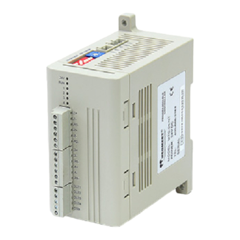
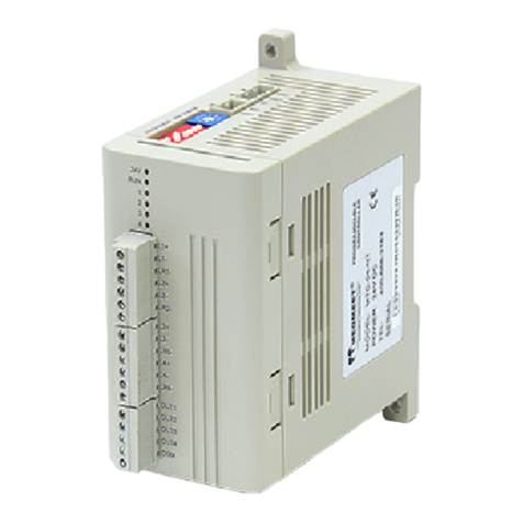
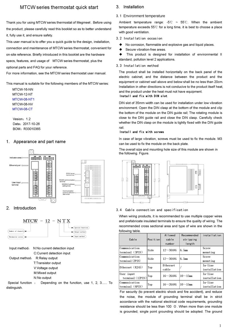
Megmeet MTC-04-NVT User manual

1
MTC-04-NVT Thermostat User Manual
Thank you for using Megmeet MTC-04-NVT module. Before using the
PLC product, please carefully read this booklet so as to better
understand it, fully use it, and ensure safety.This user manual is to offer
you a quick guide to the design, installation, connection and
maintenance of MTC-04-NVT module, convenient for on-site reference.
Briefly introduced in this booklet are the hardware specs, features, and
usage of MTC-04-NVT module, plus the optional parts and FAQ for
your reference.
This manual MTC-04-NVT module for the following members:
MTC-04-NVT Thermostat User Manual
Version 1.0
Revision date June 16, 2012
BOM
1.Introduction
Model description as 1-1.
VT:Analog and crystal
temperature control, 4
transistor alarm, 4 I/O port
input
Input method
N: No CT (Current test)
Input
The same input and
output channels of
channel number and
module number
Thermostat
Megmeet
VT
M
TC
04
-
-
N
Table 1-1 Module Description
2.Wiring Instructions
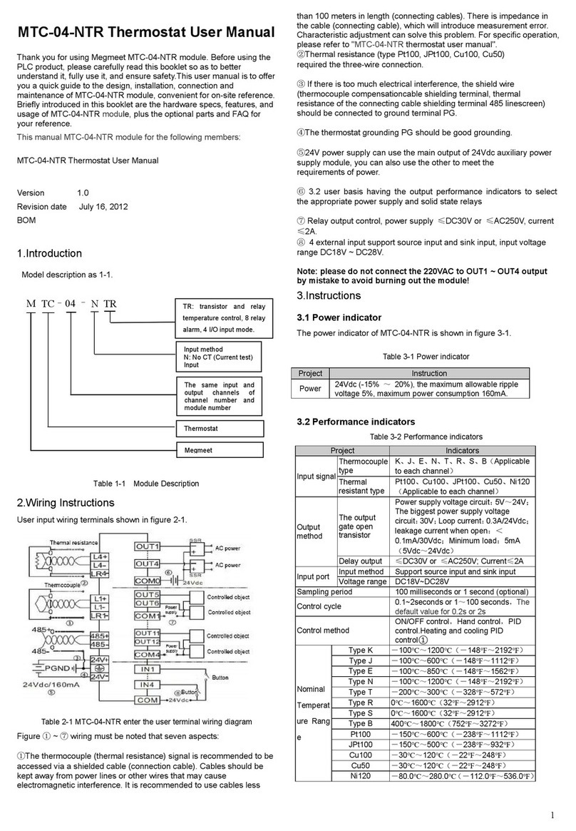
User input wiring terminals shown in figure 2-1.
Table 2-1 MTC-04-NVT enter the user terminal wiring diagram
Figure ①~⑦wiring must be noted that seven aspects:
①The rmocouple (thermal resistance) signals suggested accessing by
shieded compensation cable. Cables away from power lines
or other wires may produce electromagnetic interference. It is
recommended to use less than 100 m compensation cable (connecting
cable) that be suscepted by noise interference Compensation cable
(cable) exist resistance, will introduce measurement error, adjustment
feature to resolve this issue, please refer to the specific
operation "MTC-04-NVT thermostat user manual."
②Thermal resistance (type Pt100, JPt100, Cu100, Cu50)
required the three-wire connection.
③If there is too much electrical interference, the shield wire
(thermocouple compensationcable shielding terminal, thermal
resistance of the connecting cable shielding terminal 485 linescreen)
should be connected to ground terminal PG.
④The thermostat grounding PG should be good grounding.
⑤24V power supply can use the main output of 24Vdc auxiliary power
supply module, you can also use the other to meet the
requirements of power.
⑥3.2 user basis having the output performance indicators to select
the appropriate power supply and solid state relays
⑦Output control of analog quantity, there are four groups of analog
quantity (V1+/I1+/VI1-; V2 + / I2 + / VI2 -; V3 + / I3 + / VI3 -;
V4+/I4+/VI4-), select voltage control or current control output in each
group of analog quantities when temperature control. Current drive load
≤350Ω, voltage drive load≥2KΩ
⑧4 external input support source and sink input, input voltage range
DC18V ~ DC28V.
3.Instructions
3.1 Power indicator
The power indicator of MTC-04-NVT is shown in figure 3-1.
Table 3-1 Power indicator
Project
Instruction
Power
24Vdc (-15% ~20%), the maximum allowable ripple
voltage 5%, maximum power consumption 160mA.
3.2 Performance indicators
Table 3-2 Performance indicators
Project
Indicators
Input
signal
Thermocoupl
e type
K、J、E、N、T、R、S、B(Applicable to each channel)
Thermal
resistant type
Pt100、Cu100、JPt100、Cu50、Ni120(Applicable
to each channel)
Analog
output
Output
method
4~20mA,0~20mA;0~1V,0~5V,1~5V,0~10V(optional
)①
Precision
0.5%
Specification
Current drivers load ≤350 Ω,voltage driving load
≥2KΩ
Output
method
The output
gate open
transistor
Power supply voltage circuit:5V~24V;The
biggest power supply voltage circuit:30V;Loop
current:0.3A/24Vdc;leakage current when open:
<0.1mA/30Vdc;Minimum load:5mA(5Vdc~
24Vdc)
Input
port
Input method
Support source input and sink input
Voltage
range
DC18V~DC28V
Sampling period
100 milliseconds or 1 second (optional)
Control cycle
0.1~10 seconds or 1~100 seconds,The default
value for 0.2s or 2s
Control method
ON/OFF control,Hand control,PID control.Heating
and cooling PID control②
Nominal
Tempe
rature
Type K
-100℃~1200℃(-148℉~2192℉)
Type J
-100℃~600℃(-148℉~1112℉)
Type E
-100℃~850℃(-148℉~1562℉)
Type N
-100℃~1200℃(-148℉~2192℉)
Type T
-200℃~300℃(-328℉~572℉)

2
Project
Indicators
Range
Type R
0℃~1600℃(32℉~2912℉)
Type S
0℃~1600℃(32℉~2912℉)
Type B
400℃~1800℃(752℉~3272℉)
Pt100
-150℃~600℃(-238℉~1112℉)
JPt100
-150℃~500℃(-238℉~932℉)
Cu100
-30℃~120℃(-22℉~248℉)
Cu50
-30℃~120℃(-22℉~248℉)
Ni120
-80.0℃~280.0℃(-112.0℉~536.0℉)
Precisio
n
Thermocoupl
e
± 0.3% input range.Ambient temperature
compensation error ≤2℃
Thermal
resistant
± 0.5% input range
Isolation
The sampling channel is isolated from the power
supply, the sampling channel is isolated from the
output, and the channels are isolated from each
other
Note①: Please do not connect the MTC with the heating execution
object before selecting the temperature control mode of the simulation
output, so as to avoid misoperation of the heating equipment. This
setting is effective only when the MTC is reenergized after the
temperature control mode of analog output is selected and saved.
Note②:When the input types of channel 2 and channel 4 are selected
as 0, the simulated outputs V2+/I2+ and V4+/I4+ will be automatically
assigned to the refrigeration control outputs of channel 1 and channel 3.
If the input type of channel 1 to channel 4 is not selected as 0, and are
set to the heating and cooling control function, then the refrigeration
control of each channel can choose OUT1 ~ OUT4 to output, or through
the PLC read MTC #733 (refrigeration output state) register to use the
PLC I/O port output refrigeration control.
3. 3 Buffer Zone(BFM)
MTC-04 Modbus or MCbus through the BFM and the main module
temperature data and other information exchange. Reading and writing
attributes of buffer can use MODBUS or MCBUS instructions for
reading and writing. If you read the reserve unit, will get zero value.
Save mark Y representative with the parameter save function, can be
flash memory, marked N said cannot be flash memory. Using MODBUS
agreement, most once writeable only 50 BFM unit. BFM unit part
content as follows:
1. The channel operation monitoring;
2. Channel characteristics set;
3. Control function setting;
4. BFM parameters save Settings;
5. Other.
For more about the PID, set, alarm, MCbus and other related content
and routines, please refer to” the MTC-04-NVT thermostat user manual
".
3. 3.1 The channel operation monitoring
MTC-04-NVT buffer (BFM) to monitor the operation of the channel
contents in Table 3-3.
Table 3-3 The channel operation monitoring of MTC-04-NVT buffe(BFM)
BFM
Contents
Remarks
na
tur
e
Sa
ve
CH1
CH2
CH3
CH4
#701
#702
#703
#704
Measured value
(PV)*1
Units: 0.1 ℃
and 0.1 ℉
R
N
#709
#710
#711
#712
Heat side
control output
(MV) * 2
The default
value: 0.0%
(percentage
show)
R
N
#717
#718
#719
#720
More
paragraphs of
the currently
executing
period control *
3
Default value:
0.0%
(expressed as a
percentage)
R
N
#725
#726
#727
#728
Multi-step
control current
execution
segment * 3
Default value:0
Range:0~8
R
N
#733
Output state of
refrigeration
end *4
Default value:0
R
N
#734
Input port
status*5
Default value:0
R
N
#735
Error status
word * 6
Default value:0
R
N
BFM
Contents
Remarks
na
tur
e
Sa
ve
CH1
CH2
CH3
CH4
#736
Set value range
error address*7
0:normal
Other values:
setting the
wrong BFM
address
R
N
#737
Cold junction
temperature*8
Default value:0
R
N
#738
#739
#740
#741
Work status
word * 9
Default value:0
R
N
* 1. #701 ~ #704:The measured value of channel 1 to channel 4. The
unit is determined according to the input type (#901 ~ #904). When the
mode is Celsius, the unit is 0.1℃; when the mode is Fahrenheit, the
unit is 0.1℉.
* 2. #709 ~ #712:Heat sidecontrol output value MV; #717 ~ #720:
cooling hot side control output value MV; The control output value of the
channel obtained by the control algorithm.
* 3. #725 ~ #728: Each channel Multi-step setting executes the current
segment. The segment number being executed when multiple segment
Settings are displayed. 0: indicates that the execution state is not set in
multiple segments or that multiple segments are completed.
* 4. #733: Output status of refrigeration end. Bit0 corresponds to the
output state of the refrigeration end of channel 1, Bit1 corresponds to
the output state of the refrigeration end of channel 2, and so on. When
is 1, the output of the refrigeration end is effective; when is 0, the output
of the refrigeration end is invalid.
* 5. #734: Input port status. Bit0 corresponds to input port 1, Bit1 to
input port 2, and so on. A value of 1 indicates that the input is valid, and
a value of 0 indicates that the input is invalid.
* 6. The failure status information of #735 is shown in table 3-4.
Table3-4 BFM#735 State Information
A state of BFM#735
ON(1)
OFF(0)
b0:Error
When b1 ~ b15 any error occurs,
this flag is 1 (b1 ~ b2 in any
one of 1, stop all channel AD
converter)
Correct
b1:Save
-
-
b2:Hardware fault
AD converter or other hardware
failure
Hardware
normal
b3:Set value
backup error
When the interference and
the MTC due to an internal error
occurs, the flag will change
to 1. Then if you turn the
power off, still not be clear error,
please contact the sales agent or
our
Data
backup
normal
b4:The cold end
temperature
compensation error
b5:AD transform
digital range errors
AD transform digital output value
is less than -1 or greater than
4096, the flag is 1
Digital
output
value is
normal
b6:Set data
recovery error
When the interference and
the MTC due to an internal error,
if error reading backup data, the
flag is 1
-
b7:Save
-
-
b8~b15 Broken
accidentally
detection (only
support
thermocouple)
1 ~ 4 channel thermocouple
broken accidentally, the flag is 1
No broken
accidentall
y wrong
channel
* 7. #736: error address setting value range. Incorrect BFM area code
is displayed.
* 8. #737: reflects the current cold end temperature.
* 9. #738 ~ #741: status word for each channel. Shows the error state
and control state of each channel, #738 corresponds to channel 1,
#739 corresponds to channel 2, and so on. See table 3-5 for specific
information.

3
Table 3-5 each channel error status and control of the state
Bite
Definition
ON(1)
OFF(0)
b0~b3
Alarm 1 ~ 4 state
Alarm
No alarn
b4
Sign of
Initialization
complete
Initialization complete
Initialization
unfinished
b5
Self-tuning state
Auto-tuning state
Status of no
self-tuning
b6
Control state
Control state
uncontrolled
state
b7
Control
completion status
The temperature reaches
setting and in a stable
state
Incomplete
control
b8~b15
Save
-
-
3. 3.2 Channel characteristics set
MTC-04 buffer (BFM) channel characteristics set as table 3-6
Table 3-6 MTC-04-NVT buffer (BFM) channel characteristics set
BFM
Content
Remarks
Nat
ure
Sa
ve
CH1
CH2
CH3
CH4
#200
Restore
factory
setting*1
Default value:0
R/W
N
#201
Change
Settings
allowed*2
Default value:1,
Allows to change
0:Not Allowed
To Change
R/W
N
#801
#802
#803
#804
Digital filter
set of one
step
Default value:0
Range:0~100
(Seconds)
R/W
Y
#809
#810
#811
#812
D0*3
Default value:0
R/W
Y
#817
#818
#819
#8209
D1*3
Default value:
12000(With the
input type
change)
R/W
Y
#825
#826
#827
#828
A0*3
Default value:0
R
N
#833
#834
#835
#836
A1*3
Default value:
12000
(With the input
type change)
R
N
* 1. After #200 is set to 1, all BFM units of the module are reset to their
default values.
* 2. Change Settings allowed for BFM. Setting BFM#201 to 0 will
prevent the user from making inadvertent adjustments to BFM. Once
the disable Settings feature is set, it remains in effect until the allow
command is set (#201 = 1).
* 3. #801 ~ #804: set the data cache D0 for each channel; #809 ~ #812:
each channel feature sets the data cache D1. Use the two-point
method to set channel characteristics, D0, D1 represents the channel
output digital quantity, A0, A1 represents the channel actual input
temperature value, each channel occupies 4 words. Considering the
convenience of the user's setting, and without affecting the realization
of the function, A0 was fixed as 0℃, and A1 was fixed as the maximum
of the measurement range in the current mode. If you change the D0
and D1 values of the channel, you can change the channel
characteristics. D0 and D1 can be adjusted ±1000 on the basis of
factory setting. If the current mode uses Celsius, the adjustment range
is ±100℃; if the current mode uses Fahrenheit, the adjustment range
is ±100℉. If a value is set beyond this range, the MTC will not accept
it and will keep the original valid setting.
3. 3.3 control function setting
MTC-04-NVT buffer (BFM) set the control function of the content to
table 3-7.
Table 3-7 MTC-04 buffer (BFM) the control function of the set
BFM
Content
Remarks
Natu
re
Sa
ve
CH1
CH2
CH3
CH4
#901
#902
#903
#904
Input type *1
Default value:0
R/W
Y
#909
#910
#911
#912
Set value
(SV) * 2
Default value:
0.0
Unit:0.1℃/℉
R/W
Y
#917
#918
#919
#920
Proportional
cycle time * 3
Default value:2
Range:1~100
R/W
Y
BFM
Content
Remarks
Natu
re
Sa
ve
CH1
CH2
CH3
CH4
#925
#926
#927
#928
Heat side
proportional
band
Default value:
30
Unit:0.1%
Range:0.1%~
1000.0%
R/W
Y
#933
#934
#935
#936
Heat side int
egral time
Default value:
240
Range:1~3600
(Seconds)
R/W
Y
#941
#942
#943
#944
Heat side
Derivative
time
Default value:
60
Range:0~3600
(Seconds)
R/W
Y
#957
#958
#959
#960
Cool side
proportional
band
Default value:
30
Unit:0.1%
Range:0.1%~
1000.0%
R/W
Y
#965
#966
#967
#968
Cool side int
egral time
Default value:
240
Range:1~3600
(Seconds)
R/W
Y
#973
#974
#975
#976
Cool side
derivative
time
Default value:
60
Range:0~3600
(Seconds)
R/W
Y
#981
#982
#983
#984
Overlap/dead
band*4
Default value:0
No overlapped
non-inductive
belt
Setting
range:-input
range~+input
range
R/W
Y
#989
#990
#991
#992
Undershoot
suppression
factor*5
Water-cooled
default
Air-cooled
default
Range:0~1000
R/W
Y
#997
Run/stop
transfer of
CH1-CH4 *6
Default value:
B0000
0:Stop 1:Start
R/W
Y
M0
M1
M2
M3
Run/stop
transfer of
CH1-CH4 *6
Default value:
B0000
0:Stop 1:Start
R/W
Y
#999
Auto-tuning
setting of
CH1- CH4 *7
Default value:
B0000
0:Not self-tuning
or auto-tuning h
as been
completed
1:Auto-Tune
R/W
Y
M8
M9
M10
M11
Auto-tuning
setting of
CH1- CH4 *7
Default value:0
0:Not self-tuning
or auto-tuning h
as been
completed
1:Auto-Tune
R/W
Y
#100
0
#100
1
#100
2
#100
3
Control mode
setting
Default value:2
0:Hand 1:
ON/OFF 3:PID
R/W
Y
#100
8
#100
9
#101
0
#101
1
Heat/Cool
action*8
Default value:1
0:Cool control
1:Heat control
2:Heat and cool
(air cooling)
3:Heat and cool
(water cooling)
4:Position ratio
PID
R/W
Y
#101
6
#101
7
#101
8
#101
9
Hand output
value
Default value:0
Range:0.0~
100.0(%)
R/W
Y
#102
4
#102
5
#102
6
#102
7
Adjust
sensitivity
(ON/OFF
control
Default
value:100
Unit:0.1℃/℉
Range:0~999
R/W
Y

4
BFM
Content
Remarks
Natu
re
Sa
ve
CH1
CH2
CH3
CH4
method is
effective)
BFM
Content
Remarks
Nat
ure
Sa
ve
CH1
CH2
CH3
CH4
#103
2
#103
3
#103
4
#103
5
Auto-tuning
setting of
CH1- CH4
Default value:0
Unit:0.1℃/℉
Range:±input
range
R/W
Y
#110
1
#110
2
#110
3
#110
4
Heat side
proportional
band
adjusting
factor
Default value:
100%
Setting
range:0~1000%
R/W
Y
#110
9
#111
0
#111
1
#111
2
Heat side
integral time
adjusting t
factor
Default value:
100%
Setting
range:0~1000%
R/W
Y
#111
7
#111
8
#111
9
#112
0
Heat side
derivative
time adjusting
t coefficient
Default value:
100%
Setting
range:0~1000%
R/W
Y
#112
5
#112
6
#112
7
#112
8
Cool side
proportional
band
adjusting t
factor
Default value:
100%
Setting
range:0~1000%
R/W
Y
#113
3
#113
4
#113
5
#113
6
Cool side
integral time
adjusting t
factor
Default value:
100%
Setting
range:0~1000%
R/W
Y
#114
1
#114
2
#114
3
#114
4
Cool side
derivative
time adjusting
t factor
Default value:
100%
Setting
range:0~1000%
R/W
Y
#114
9
#115
0
#115
1
#115
2
Set change
rate limit rise
* 10
Default value:0
Range:0~range,
Unit:℃/second
R/W
Y
#115
7
#115
8
#115
9
#116
0
Set change
rate limit drop
* 10
Default value:0
Range:0~range,
Unit:℃/second
R/W
Y
#116
5
#116
6
#116
7
#116
8
Selection of
temperature
control object
characteristic
s * 11
Default value:0
0:Slow heating
object
1:Slow heating
object
R/W
Y
#117
3
#117
4
#117
5
#117
6
PID algorithm
selection
Default value:1
0:Fuzzy PID
algorithm
1:Intelligent PID
algorithm
R/W
Y
#118
1
#118
2
#118
3
#118
4
PID output
upper limit
setting
Default value:
0.0%
Setting
range:0.0%~100.
0%
R/W
Y
#118
9
#119
0
#119
1
#119
2
PID output
lower limit
setting
Default value:
0.0%
Setting
range:0.0%~100.
0%
R/W
Y
#119
7
#119
8
#119
9
#120
0
PID output
dead zone
Default value:
0.0%
Setting
range:0.0%~100.
0%
R/W
Y
#120
5
#120
6
#120
7
#120
8
Manual /
automatic
bumpless
switching
setting * 12
Default value:0
0:Turn off
bumpless
switching
1:Turn on
bumpless
switching
R/W
Y
BFM
Content
Remarks
Nat
ure
Sa
ve
CH1
CH2
CH3
CH4
#121
3
#121
4
#121
5
#121
6
External
manual /
automatic
bumpless
switch setting
* 13
Default value:0
0:Turn off
external manual /
automatic switch
input
1:Turn on
external manual /
automatic switch
input
R/W
Y
#1305
OUT 1 output
connection *
14
Default value : 0
connect channel
1
alarm 1 mode
1: Turn off the
output
2: Turn on the
output
3: Channel 1
heating, cooling
and cooling
output
4: Channel 1
heating output
R/W
Y
#1306
OUT 2 output
connection
Default value : 0
connect channel
2
alarm 1 mode
1: Turn off the
output
2: Turn on the
output
3: Channel 2
heating, cooling
and cooling
output
4: Channel 2
heating output
R/W
Y
#1307
OUT 3 output
connection
Default value : 0
connect channel
3
alarm 1 mode
1: Turn off the
output
2: Turn on the
output
3: Channel 3
heating, cooling
and cooling
output
4: Channel 3
heating output
R/W
Y
#1308
OUT 4 output
connection
Default value : 0
connect channel
4
alarm 1 mode
1: Turn off the
output
2: Turn on the
output
3: Channel 4
heating, cooling
and cooling
output
4: Channel 4
heating output
R/W
Y
* 1. #901 ~ #904: input type . Select the input type and temperature
mode of each channel, #901 corresponds to channel 1, #902
corresponds to channel 2, and so on. When the channel is set to 0, the
channel is closed and the corresponding channel does not perform A/D
conversion. The meaning of the pattern is shown in table 3-8.
Table 3-8 Model specification
NO.
value
(decimal)
Significance
1
1
K-type thermocouple .Scope:-100.0~200.0℃
2
2
K-type thermocouple.Scope:-100.0~400.0℃
3
3
K-type thermocouple .Scope:-100.0~1200.0℃
4
4
K-type thermocouple .Scope:-148.0~800.0℉
5
5
K-type thermocouple input range:-148.0~
2192.0℉
6
6
J-type thermocouple .Scope:-100.0~200.0℃

5
NO.
value
(decimal)
Significance
7
7
J-type thermocouple .Scope:-100.0~400.0℃
8
8
J-type thermocouple .Scope:-100.0~600.0℃
9
9
J-type thermocouple .Scope:-148.0~752.0℉
10
10
J-type thermocouple .Scope:-148.0~1112.0℉
11
11
E-type thermocouple .Scope:-100.0~200.0℃
12
12
E-type thermocouple .Scope:0.0~850.0℃
13
13
E-type thermocouple .Scope:-148.0~1562.0℉
14
14
N-type thermocouple .Scope:-100.0~
1200.0℃
15
15
N-type thermocouple .Scope:-148.0~
2192.0℉
16
16
T-type thermocouple .Scope:-200.0~200.0℃
17
17
T-type thermocouple .Scope:-200.0~300.0℃
18
18
T-type thermocouple .Scope:0.0~300.0℃
19
19
T-type thermocouple .Scope:-328.0~400.0℉
20
20
T-type thermocouple .Scope:-328.0~572.0℉
21
21
T-type thermocouple .Scope:0.0~572.0 ℉
22
22
R-type thermocouple .Scope:0.0~1600.0℃
23
23
R-type thermocouple .Scope:32.0~2912.0℉
24
24
S-type thermocouple .Scope:0.0~1600.0℃
25
25
S-type thermocouple .Scope:32.0~2912.0℉
26
26
Pt100,.Scope:-50.0~150.0℃
27
27
Pt100,.Scope:-150.0~600.0℃
28
28
Pt100,.Scope:-238.0~300.0℉
29
29
Pt100,.Scope:-238.0~1112.0℉
30
30
JPt100,.Scope:-50.0~150.0℃
31
31
JPt100,.Scope:-150.0~500.0℃
32
32
JPt100,.Scope:-238.0~300.0℉
33
33
JPt100,.Scope:-238.0~932.0℉
34
34
Cu100,.Scope:-30.0~120.0℃
35
35
Cu100,.Scope:-22.0~248.0℉
36
36
Cu50,.Scope:-30.0~120.0℃
37
37
Cu50,.Scope:-22.0~248.0℉
38
38
Ni120,.Scope:-80.0℃~280.0℃
39
39
Ni120,.Scope:-112.0℉~536.0℉
40
40
PT100,.Scope::-150.0~300.0℃
41
41
B-type thermocouple.Scope: 400.0 ~ 1800.0℃
42
42
B-type thermocouple.Scope .Scope: 752.0~
3272.0℉
43
43
K-type thermocouple.Scope -100.0~600.0℃
44
44
K-type thermocouple.Scope -100.0~800.0℃
45
45
J-type thermocouple.Scope -100.0~800.0℃
46
46
J-type thermocouple.Scope -100.0~1200.0℃
47
47
J-type thermocouple.Scope-148.0~2192.0℉
48
48
T-type thermocouple.Scope-200.0~400.0℃
49
49
T-type thermocouple.Scope-328.0~752.0℉
Explanation:Celsius=5/9×((Fahrenheit)-32)
* 2. #909 ~ #912: temperature setting. Set the target value of each
channel temperature control. The unit is determined according to the
input type (#901 ~ #904). When the mode is Celsius, the unit is 0.1℃;
when the mode is Fahrenheit, the unit is 0.1℉.
* 3. #917 ~ #920: proportional cycle time. The control output cycle of
each channel is set, the setting range is 1 ~ 100, the default value is 2,
the unit is determined according to the temperature control object
characteristic selection of #1165 ~ #1168, when the temperature control
object is selected for slow temperature rise, the unit of temperature
control period is seconds, but when the temperature control object is
selected for fast temperature rise, the unit of temperature control period
is hundreds of milliseconds.
* 4. #981 ~ #984: overlap/deaband.
* 5. #989 ~ #992:Undershoot suppression factor.
* 6. #997: Run/stop transfer. Bit0 corresponds to channel 1, Bit1
corresponds to channel 2, and so on. Is 1 when the channel opens the
heating temperature control, is 0 when the channel closes the heating
temperature control; M0 ~ M3 elements map directly to Bit0 ~ Bit3 of
#997, and the start and stop of each channel can be directly controlled
by setting M0 ~ M3 elements.
* 7. #999: Auto-tuning enable. Bit0 corresponds to channel 1, Bit1 to
channel 2, and so on. When is 0, it means self-tuning is closed or
self-tuning is completed; when is 1, it means self-tuning is opened (at
this time, the channel should be set in the state of temperature control
and heating); M8 ~ M11 elements map directly to Bit0 ~ Bit3 of #999. By
setting M8 ~ M11 elements, you can also directly control the opening
and closing of each channel self-tuning.
* 8. #1008 ~ #1011: heat/coo action. When the "position proportional
PID" mode is selected, the MV value of temperature control output is
the change of PID output value.
* 9. #1016 ~ #1019:hand output . Set the duty cycle of the constant
output of each channel, the setting range is: 0 ~ 1000 (unit is 0.1%), the
default value is 0.
* 10. #1149 ~ #1152: set the rate of change to increase. #1157 ~ #1160:
set the rate of change to decrease. Range 0 ~ range, when set to 0, it
means that there is no limit for l/l/cooling, and the unit is ℃/ min.
* 11. #1165 ~ #1168:Control action. When the object of slow
temperature rise is selected, the temperature control output period,
integral time and differential time are measured in seconds. When the
object of rapid temperature rise is selected, the temperature control
output period, integral time and differential time are measured in
hundreds of milliseconds.
* 12. #1205 ~ #1208: manual/automatic no disturbance switch Settings.
When the manual/automatic non-disturbance switch setting is effective,
the module will switch from manual mode to automatic mode or from
automatic mode to manual mode, and the temperature control output
MV value will switch smoothly to the next output state.
* 13. #1213 ~ #1216: external manual/automatic switching of input
Settings. When both external manual/automatic input Settings and
external input are valid, the manual/automatic temperature control
modes switch to each other. The external port inputs IN1 control
channel 1, IN2 control channel 2, and so on.
* 14. #1305: OUT1 input connection. OUT1 output Settings, can be set
to alarm output can be forced to output high or low level, but also can
be set to temperature control of the heating or cooling output, OUT2,
OUT3, OUT4 and OUT1 similar.
3. 3.4 BFM parameters save Settings
MTC-04-NVT buffer (BFM) of the BFM parameter set to save the
contents of Table 3-9.
Table 3-9 MTC-04-NVT buffer (BFM) BFM parameters save Settings
BFM
Content
Remarks
Nat
ure
Sa
ve
CH1
CH2
CH3
CH4
#700
Module
paramet
ers to
save *1
Default value:0
(Does not
save parameters)
1:Save the
startup parameter
s
R/
W
N
Note: when the startup parameter is saved, #700 will automatically
clear to zero.
3. 3.5 Others
MTC-04-NVT buffer (BFM) of the other content shown in Table 3-10.
Table 3-10 MTC-04-NVT buffer (BFM) of the other content
BFM
Content
Remarks
Nat
ure
Sa
ve
CH1
CH2
CH3
CH4
#4094
Module software
version
information *1
0x2000
R
N
#4095
Identification of
the thermostat *2
0xB443
R
N
*1.BFM#4094:Module software version information.
*2.BFM#4095:Module identification number. MTC-04-NVT
identification number is 0xB443. Programmable logic controller of user
program can be used in a program in the identification number, in
transmitting/receiving data confirm that this before the thermostat.
4.Operation check
4. 1 Routine check
1. Check the wiring meets the requirements of the analog
input (reference 2 wiring instructions).
2. Check the MTC-04-NVT's reliability into the first terminal
MTC-04-NVT.
3. Check available to MTC-04-NVT of the 24Vdc power supply is
overloaded.

6
4. Check the application to ensure that the application is selected in
the correct methods of operation and parameter range, with particular
attention to the timing of the BFM with special
operations area regulations required timing operation.
4. 2 Fault inspection
If MTC-04-NVT run normally, please check the following projects.
Check 24 V indicator state.
Light: 24 Vdc power supply normal;
Extinguish: 24 Vdc power supply may fault; If 24 Vdc power supply
normal, the MTC-04-NVT fault.
Check the state RUN indicator
High-speed flash: MTC-04-NVT is operating normally.
Slow Flashing: Check BFM # 735, BFM # 736 in the information.
Always on or off::MTC-04-NVT crash.
Notice to users
1. Warranty means the thermostat body.
2. Warranty period is 18 months, under normal use during the warranty
period, product failure or damage, my company free of maintenance.
3. Warranty start date time manufacturing factory, the machine code
is the sole basis to determine the warranty
period, no machine-coded equipment out of warranty.
4. Even during the warranty period, the following
situations, certain maintenance costs will be charged:
Not caused by user manual for operating the machine failure.
Due to fire, flood, abnormal voltage and other damage caused
by machinery.
The thermostat function for non-normal damage.
Disassemble the thermostat.
5. Service charges based on actual costs, such as another contract,
the contract principle of priority treatment.
6. If you have any question please contact the distributor or
directly contact me.
Shenzhen Megmeet Control Technology Co.,Ltd
Address: 5th Floor,Block B,Ziguang Information Harbor, Langshan Rd,
Science& Technology Park, Nahshan District, Shenzhen
Homepage: www.megmeet.com
All rights reserved. The contents in this document are subject to change
without notice.
Other manuals for MTC-04-NVT
1
Table of contents
Other Megmeet Thermostat manuals
