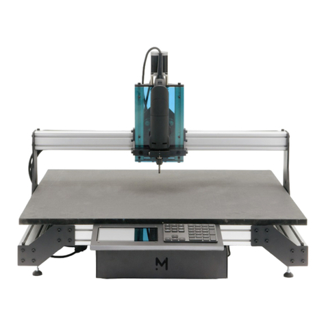
MEKANIKA CNC EVO User manual

CNC EVO/PRO
MACHINE INTERFACE PRESENTATION

2
space
TOUCHSCREEN
INTRODUCTION
Our machines come out-of-the-box with an interface unit, which is composed of two
elements:
• a 7 inches TFT touchscreen ;
• a customized Bluetooth keypad.
The touchscreen will allow you to control your machine via PlanetCNC, but also to
navigate on the Raspberry Pi if you need to browse your folders, edit some les, or even
browse the web.
The Bluetooth keypad oers an alternative to handle your machine easily and intuitively:
most of the keys have been remapped to specic functionalities of PlanetCNC and will
serve as useful shortcuts to control it.
If you wish to use your own screen, keyboard & mouse as an interface to control the
machine, it is of course possible. Simply connect your devices at the back of the control
unit and change the resolution of the Raspberry Pi to t your new screen.
INTERFACE UNIT
Bluetooth
pairing button
USB charger
(can be plugged on the
front of the control unit)
ON/OFF

3
When you turn on the machine, PlanetCNC will automatically starts after a few seconds
and you will arrive on the screen shown below.
Here is an overview of the dierent areas and functionalities of the software:
1. X, Y & Z axes current position (working and absolute coordinates of the machine)
2. Real-time machine travel speed & spindle rotation speed (Feed & Speed)
3. Manual travel speed of the machine and controls (Jog)
4. General menu
5. G-code control menu (Play, Pause, Stop,...)
6. Machine actions menu (Homing, Tool measure length,...)
7. Graphical interface & 3D view
8. G-code panel (current loaded code)
9. G-code command line (MDI)
Some functionalities of PlanetCNC are only accessible using the touchscreen, but the
most important ones can be quickly activated using the keypad. These functionalities
share the same icons on the screen and on the keys.
MAIN SCREEN
PLANETCNC

4
AXES COORDINATES
PLANETCNC
The rst section of the screen displays the real-time coordinates of the machine. There
are two types of coordinates that you will use:
• Working coordinates, representing the position of the tool relative to the work-
piece, displayed in blue.
• Machine coordinates, representing the position of the tool relative to the machine
origin, X0 Y0 Z0 located at the front bottom left of the machine, displayed in green.
You can toggle in between the two using the tabs, as shown on the images below.

5
FEED & SPEED
JOG
PLANETCNC
The second section of the screen displays two values: the current travel speed of the
machine (also called Feed) and the rotation speed of the spindle (also called Speed),
as dened inside the G-code that is loaded in the program.
If you click on the icons, the section expands and shows new functions. They allow you
to increase/decrease the feed & speed in real-time, while it is working and reading a
G-code. For instance, on the image below, the machine is supposed to travel at a speed
of 2000mm/min (Feed F2000), but the speed was decreased by 70% down to 1400mm/
min.
The jog section allows you to move your machine freely, at a certain speed. This speed
can be changed by double-clicking on the number indicated on the image below.
To move the machine, press on the arrows with the touchscreen or use the following
keys:

6
PLANETCNC
The top bar contains shortcuts to 5 contextual menus, in which you can nd all the
functionalities of PlanetCNC, including the language preferences and the settings. If
you want to know more about these, you can nd all the information you need inside the
PlanetCNC TNG documentation, which can be downloaded on the support page of our
website.
GENERAL MENU
G-CODE CONTROL
These 4 buttons allow you to:
Load a G-code
le into
PlanetCNC
Start the loaded
G-code
Temporarily stop
the G-code (can
be resumed)
Permanently stop
the G-code (can’t
be resumed)

7
PLANETCNC
MACHINE ACTIONS
Emergency stop. Stops all motion of the machine immediately. Please note
that emergency stop should be activated using the physical push-button,
not using the touchscreen.
Go to XYZ zero. The machine will rapidly move towards the X0 Y0 Z0 work-
ing coordinates.
Dene XY zero. Forces the X0 & Y0 working coordinates at the current
location of the machine.
Dene Z zero. Forces the Z0 working coordinates at the current location of
the machine.
Tool measure length. The machine will slowly travel down until it touches
the metal part of the probing device. It will then dene the Z0 working coor-
dinate to be perfectly aligned with the bottom surface of the device.
Home. The machine will move along all its axes until it touches the limit
switches. This function allows to reference the absolute origin of the machine.
Square Gantry. The machine will move along the Y-axis until it touches the
limit switches on both sides. This allows you to be sure that the Y-axis of the
machine is perfectly perpendicular to the X-axis.
Go to XY zero. The machine will rapidly move towards the X0 Y0 working
coordinates.
Among these 8 actions, 4 of them are available on the keypad as well:
Before starting the square gantry, bring the machine close to the front since it
will move slowly. Never stop that action while it’s running, otherwise you will
have to recongure the Y-axis output (see our troubleshooting guide).
For more accurate results, start the tool measure length action with the probe
device close to your workpiece.

8
In the middle of the screen, you will nd a 3D view representing the reachable XYZ
working volume of the machine. The orange cone represents the tool, so the central
point of the machine from which all coordinates are calculated.
If a G-code is loaded, the graphical interface will also display the toolpath that the ma-
chine will follow to mill that part.
The toolbar located on top can be used to change the views (top, side,...), but also to
zoom on the workpiece, on the tool, etc.
GRAPHICAL INTERFACE
PLANETCNC

9
The last section of the screen is used to display the loaded G-code. You can use the it
to browse your code, to execute it line by line, or even to start operations in the middle
of it, as shown on the picture below.
At the bottom of this section, you can nd a command line, also called MDI, that is used
to type G-code manually and send it directly to the machine. For instance, the com-
mand shown below will move the machine at maximal speed to the working coordi-
nates X50 and Y100. If you want to know more about this, you can nd all the informa-
tion you need inside the PlanetCNC G-code documentation, which can be downloaded
on the support page of our website.
G-CODE PANEL & MDI
PLANETCNC

10
RASPBERRY PI
Our machines run on a Raspberry Pi that is directly connected to the control interface.
It means that you can use it as you wish to organise your les, browse the web, etc. You
can access the desktop by minimizing the window of PlanetCNC.
Like with a smartphone, if you want to open a le or a program, simply press the icon
once. If you want to right-click, press the icon longer and the contextual menu will
appear. Lastly, if you need to type some text, you can open the virtual keyboard by
clicking on the taskbar icon.
TOUCHSCREEN USAGE
This manual suits for next models
1
Table of contents
Other MEKANIKA Control System manuals
