MELAG MELAseal 100+ User manual

Dear Dr.
We should like to extend our thanks for the expression of trust in our company which you have displayed through the
purchase of this MELAG product.
As an owner-run and operated family concern founded in 1951, we have a long history of successful specialization in
hygiene products for practice-based use. Our focus on innovation, quality and the highest standards of operational
reliability has established MELAG as the world’s leading manufacturer in the instrument treatment and hygiene field.
You, our customer are justified in your demand for the best products, quality and reliability. Providing "competence in
hygiene" and "Quality – made in Germany", we guarantee that these demands will be met. Our certified quality
management systems is subject to close monitoring: one instrument to this end is our annual multi-day audit conducted
in accordance with ISO 13485 and ISO 9001 conducted by the certification agency BSI. This guarantees that all MELAG
products are manufactured and tested in accordance with strict quality criteria.
The MELAG management and team.
Operating Manual
MELAseal®100+
Bar sealer

General Guidelines
Please read these operating instructions carefully before commissioning the sealing device. The instructions include
important safety information. The functionality and value-retention of this autoclave depend on the care accorded to it.
Make sure to keep the Operating Manual near to the device. It represents a component of the product.
User Group
This manual is targeted at doctors, medical assistants and service.
Symbols used
Symbol
Explanation
Indicates a dangerous situation which if not avoided could entail slight to life-threatening
injuries.
Indicates a dangerous situation which if not avoided could entail damage to the
instruments, the practice equipment or the sealing device.
Draws your attention to important information.
Formatting rules
Symbol
Explanation
OPEN
Words or phrases appearing on the display of the sealing device are marked as display
text.
see Chapter 2
Reference to another text section within this manual.
Fig. 1/(3)
Reference to a detail in a figure – in the example, to part no. 3 in figure 1.

Contents
Contents
Chapter 1 – Performance Specifications .........................................................................................5
Proper use ....................................................................................................................................................................... 5
Chapter 2 – Device Description.......................................................................................................6
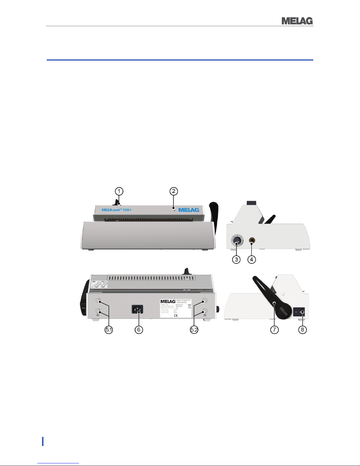
Views of the device.......................................................................................................................................................... 6
Control lamp status display and acoustic signals ............................................................................................................ 7
Chapter 3 – Initial Commissioning................................................................................................... 8
Transport and storage ..................................................................................................................................................... 8
Conditions of storage and installation.............................................................................................................................. 8
Requirements of the set-up location ................................................................................................................................ 8
Wall mounting .................................................................................................................................................................. 8
Connecting the sealing device......................................................................................................................................... 9
Commissioning .............................................................................................................................................................. 10
Simple sealing procedure .............................................................................................................................................. 10
Sealing procedure for rollstock ...................................................................................................................................... 11
Seal seam width ............................................................................................................................................................ 13
Sealing temperature ...................................................................................................................................................... 13
Chapter 4 – Optional Accessories................................................................................................. 14
Reel dispenser “standard” ............................................................................................................................................. 14
Reel dispenser “Comfort” and “Deluxe” ......................................................................................................................... 14
Wall-mounted reel dispenser......................................................................................................................................... 15
Chapter 5 – Maintenance.............................................................................................................. 16
Cleaning and regular controls........................................................................................................................................ 16
Replacing the blade....................................................................................................................................................... 16
Manufacturer's Recommendation for Routine Operation............................................................... 18
DIN Specifications.........................................................................................................................
20
Terms ............................................................................................................................................................................ 20
General information regarding the packaging and sealing procedure ........................................................................... 20
Seal seam width ............................................................................................................................................................ 20
Strength of seal seam.................................................................................................................................................... 20
Accessories and Replacement Parts.............................................................................................21
Technical Data..............................................................................................................................21

Chapter 1 – Performance Specifications
4
Safety Instructions
When operating the sealing device, please ensure that you observe the following safety instructions as
well as those contained in following chapters.
Power cable and mains socket
Only the power cable included in the scope of delivery may be connected to the sealing device.
Liquids may not be permitted to reach the interior of the sealing device. This could result in an
electrical shock or short circuiting.
Repair
Never open the housing of the sealing device. Incorrect opening and repair can compromise
electrical safety and pose a danger to the user.
The guarantee and warranty are forfeited as soon as the sealing device is opened by anyone
other than a member of a MELAG-authorized technical customer service.

Chapter 1 – Performance Specifications
5
Chapter 1 – Performance Specifications
Proper use
This sealing device is designed for application in a medical context, e.g. clinics and medical and dental
practices.
It was developed for the heat sealing of instruments in sterilization packaging.
Suitable materials
It is suitable for the heat sealing of transparent sterilization packaging according to DIN EN 868-5 such as
e.g. MELAfol.
Should you wish to use packaging materials other than those specified above, please consult your stockist
first or contact MELAG directly.
Unsuitable foils and materials
Tubular film (double-sided film) is not suitable for use in this sealing device as these types tend to
become glued together on the sealing rail, thus restricting the functionality of the sealing device.
Polyethylene film
Soft PVC film
Hard PVC film
Polyamide film
Polypropylene film
PLEASE NOTE
The use of unsuitable packaging materials carries the risk of damage to or malfunction of
the device.
Please observe the manufacturer information regarding the respective packaging materials
as well as the recommended sealing temperatures.

Chapter 2 – Device Description
6
Chapter 2 – Device Description
Scope of delivery
Please check scope of delivery before connecting the sealing device.
Standard scope of delivery
MELAseal®100+ sealing device
Power cable
Operating Manual
Certificate of Conformity
Warranty certificate
Lever
Torx key for housing screws
Views of the device
Fig. 1: Views of the device
(1) Knife handle
(2) Control lamp
(3) Rotary knob for temperature adjustment
(4) Square hole for lever (double-sided)
(5.1/5.2) Reel dispenser “comfort”
(6) Power cable socket
(7) Lever
(8) Power switch (ON/OFF)

Chapter 2 – Device Description
7
Control lamp status display and acoustic signals
Table 1: Explanation of the warning lights and the acoustic signals
Warning
lights/acoustic
signals
Possible cause
Risk management
●
illuminated yellow
The sealing device is currently
warming up or cooling down
Please wait until the pre-set sealing
temperature has been reached.
☼
Flashes red,
warning signal
The lever is depressed during
the heating phase,
The sealing temperature has
not yet been reached.
Please wait until the LED is constantly
illuminated green.
●
Illuminated green
The sealing device has reached
the pre-set sealing temperature
and is ready for operation.
The pre-
set sealing time (3 sec)
has been reached and the
sealing procedure has been
ended.
Raise the lever and remove the packaging.
☼
Flashes green
The sealing procedure is
running (3 sec) and the lever
has been depressed.
Please wait until the LED is constantly
illuminated green.
●
illuminates red,
warning signal
(malfunction)
The lever has been raised
early, despite the required
sealing time not having been
reached.
The lever has not been raised,
despite the required sealing
time having been completed.
The heating phase is taking too
long (> 5 min.); the sealing
device cannot reach the pre-set
sealing temperature.
Please keep the lever depressed until the
green LED is constantly illuminated.
Lift the lever as soon as the sealing time has
been reached so that the film is not burnt.

Chapter 3 – Initial Commissioning
8
Chapter 3 – Initial Commissioning
Transport and storage
WARNING
The use of unsuitable transport packaging can result in damage to the housing and the
device interior.
The sealing device should only be transported in its original or otherwise suitable packaging.
Storage
The device should be stored in such a way to protect against humidity.
Conditions of storage and installation
In accordance with current VDE specifications, the sealing device is unsuitable for operation in areas
exposed to the danger of explosion.
The sealing device is conceived for use outside patient surroundings. The device should be located at
least 1.5 m away (radius) from the treatment area.
Observe all the information contained in this chapter during commissioning.
DANGER
Damages to the sealing device and/or injuries can occur in case the installation conditions
are not observed.
Requirements of the set-up location
Observe the following requirements:
The site of setup is dry and dust-protected.
Sufficient clearance to the surrounding surfaces is available in order to ensure sufficient
ventilation.
The sealing device is located away from direct sunshine and outside the range of other sources of
heat
The sealing device is protected against blows or vibration.
Wall mounting
If the device is not to be placed on a table, it can be mounted on a wall.
If this is the case, we recommend using the wall-mounted roll bracket optionally available.
Proceed as follows:
1. Remove the perforated metal wall-mounting metal panels from the base of the sealing device.
2. Drill two Ø 6 mm boreholes in the wall with a clearance of 16.5 mm at the desired mounting
height.

Chapter 3 – Initial Commissioning
9
3. Insert two rawl plugs (6mm) with round-head screws (Ø3.5 x 45 mm) in the bore holes.
4. Hang the sealing device on the screws.
Connecting the sealing device
Check the following before connecting the sealing device:
The device power switch is off.
The power cable included in the scope of delivery is used for connecting.
1. Connect the one end of the power cable with the port on the rear of the sealing device and the
other end with a mains socket with an approved voltage supply (in accordance with the name
plate on the rear of the sealing device).
2. Insert the lever in the square hole on the left or right-hand side of the device as required (Fig.
1/(4)).
16.5 cm

Chapter 3 – Initial Commissioning
10
Commissioning
Switching on the sealing device
Activate the sealing device at the power switch.
The LED at the front of the sealing device (Fig. 1/(2)) will illuminate yellow after switching on. As soon as
the control lamp is continuously illuminated green, the pre-set sealing temperature has been reached and
the sealing device is ready to operate.
Simple sealing procedure
DANGER
The sealing bar is heated continuously after the sealing device has been switched on. The
surrounding metal components are hot!
Touching the hot metal surfaces can cause burns.
Never touch the metal surfaces on the cutting bar and on the rear and fore paper guide
directly.
In order to perform a simple sealing procedure, proceed as follows:
1. Introduce the packaging in the paper guide with the foil side facing upwards and push the
packaging through the pressure bar and sealing bar. Ensure maintenance of the correct
clearance between instrument and seal seam (consult the relevant section of the DIN
Specifications).
WARNING
The film side of the packaging must always face upwards. Should the packaging be inserted
incorrectly, this could result in the deposit of film residue on the sealing rail.

Chapter 3 – Initial Commissioning
11
2. Press the lever forwards to its fullest extent until it clicks.
3. Leave the lever depressed as long as the control lamp flashes green in short intervals (for 3
seconds).
4. When the control lamp is continually illuminated green again, return the leaver to its starting
position.
5. The sealing procedure has been completed successfully.
6. After every successful sealing process carry out a visual inspection of the film.
Sealing procedure for rollstock
DANGER
The sealing bar is heated continuously after the sealing device has been switched on. The
surrounding metal components are hot!
Touching the hot metal surfaces can cause burns.
Never touch the metal surface on the cutting bar and on the rear and fore paper guide directly.
Cutting the film
If the instruments are packaged from the roll in transparent sterilization packaging bags, proceed as
follows:
1. Introduce the film in the paper guide (lower slot) from the rear with the paper side facing
downwards and push the packaging forward through the pressure bar and sealing bar until
reaching the desired length.
2. Press the lever forwards to its fullest extent until it clicks.

Chapter 3 – Initial Commissioning
12
3. Leave the lever depressed as long as the control lamp flashes green in short intervals (for 3
seconds).
4. To cut the film during the sealing process, move the knife handle to the other end of the sealing
device quickly. The lever should remain depressed. Do not return the knife handle.
Sealing film bags
In order to seal the cut to length film bag, proceed as follows:
1. Place the instruments to be sterilized in the bag thus produced. Ensure maintenance of the
correct clearance between instrument and seal seam (consult the relevant section of the (DIN
Specifications).
2. Slide the open side of the bag from the front into the paper guide.
WARNING
The film side of the packaging must always face upwards. Should the packaging be inserted
incorrectly, this could result in the deposit of film residue on the sealing rail.

Chapter 3 – Initial Commissioning
13
3. Press the lever forwards to its fullest extent until it clicks.
4. Leave the lever depressed as long as the control lamp flashes green in short intervals (for approx.
3 seconds).
5. When the control lamp is continually illuminated green again, return the leaver to its starting
position.
6. The sealing procedure has been completed successfully.
PLEASE NOTE
When sealing MELAfol sealing bags with lateral creases, please observe and comply with the
special information contained in the sealing bag operating manual regarding sealing cassettes.
Seal seam width
The sealing device produces homogenous 10 mm wide seal seams with every sealing procedure.
The recommended nominal size for the width of the seal seam in the German standard DIN 58953 part 7
is only 6 mm.
Section 4.3.2 of DIN EN 868-5 requires a min. total seal width of 6 mm. The sum of the
individual seams should amount to min. 6 mm.
Sealing temperature
Continuously variable temperature regulation is performed using the rotary knob (Fig. 1/(3)) on the left-
hand side of the sealing device. The sealing temperature is determined by the type of sterilization
packaging.
When using MELAfol transparent sterilization packaging as provided by MELAG, the rotary knob should
point to the middle area marked with “MELAFOL” (corresponds to 180°C).
To reduce the sealing temperature, turn the knob leftwards in an anti-clockwise direction.
To increase the sealing temperature, turn the rotary knob rightwards in a clockwise direction.

Chapter 4 – Optional Accessories
14
Chapter 4 – Optional Accessories
Reel dispenser “standard”
The reel dispenser "standard“ is placed directly behind the sealing
device.
The rolls of film are placed into the cavity and held in position using
additional spacers located to the left and right. This prevents them
from slipping.
The reel dispenser “standard“ is hooked onto the brackets on the
rear of the sealing device.
Reel dispenser “Comfort” and “Deluxe”
The reel dispenser “Comfort“ enables space-saving storage of the
film rolls over the sealing device.
The rolls are slid onto the rod laterally and held in position via
additional spacers to the left and right. This prevents the roll from
slipping and turning as well.
In the roll dispenser "deluxe", the film rolls are stored above the
sealing device, thus saving space.
The integrated feeding device enables easy feeding of the film via a
hand wheel.
Reel dispenser "standard"
(Rear detail view)

Chapter 4 – Optional Accessories
15
The reel dispensers “Comfort“ and “Deluxe” are hooked onto the brackets on the rear of the sealing
device.
Wall-mounted reel dispenser
Mounted on the wall directly over the sealing device, the wall-
mounted roll dispenser saves space.
Reel dispenser
"Comfort"/”Deluxe”
(Rear detail view)

Chapter 5 – Maintenance
16
Chapter 5 – Maintenance
Cleaning and regular controls
The outside of the sealing device should be cleaned at least twice a year. Only use a lint-free damp cloth
stainless steel-cleaning agent suitable for use with medical products. It should not deposit any oily residue.
Observe the following instructions when cleaning:
Before every cleaning switch off the sealing device at the power switch and remove the power plug.
The cleaning cloth may never be allowed to become entirely wet in order to prevent water from
entering the interior of the sealing device.
Replacing the blade
DANGER
Failure to observe this provision can result in a short circuit and/or an electric shock.
Switch off the sealing device at the mains and remove the cable.
DANGER
Metal surfaces of the sealing device become hot during operation.
Touching the hot metal surfaces can cause burns.
Allow the sealing device to cool before opening.
Proceed as follows to replace the blade:
1. Remove the 2 TORX screws (Torx 20) from the upper side of the sealing device on the cutting
bar using the TORX screwdriver included in the scope of delivery.
2. Remove the upper rear housing cover rearwards.
3. Loosen the screws on the blade.
4. Turn the blade 180° in order to use the other side of the blade or replace it entirely.

Chapter 5 – Maintenance
17
5. Return the screws.
6. Replace the unit housing and secure with the Torx screws.
Press the fore housing cover against the rear housing cover in order to return the Torx screws.
PLEASE NOTE
When assembling the sealing device, ensure that the blade is able to move freely from side to
side.

Manufacturer's Recommendation for Routine Operation
18
Manufacturer's Recommendation for
Routine Operation
Frequency
Check/action
Criteria
Daily before
operation
Making and
checking a sample
seal seam
Visual check:
The seal seam should be distinct and even and not
contain any creases or defects.
The sealing seam should be almost identical with the
works sealing seam, i.e. an industrial seal with an
identical edge in terms of colour.
If the sealing seam is too light,
the sealing temperature and/or the contact pressure
(sealing force) is too low;
If the sealing seam is brown,
the sealing temperature is too high or the sealing duration
too long
Mechanical check
Tear-resistance check: the strength required to open
the seam must be exactly equal to that required to
open the factory-produced seam Peel test1)
When peeled off, the paper should free itself from the
film, leaving almost no residue
Following every
sterilization
Batch-related check
of the seam
Control the entire packaging for dryness and integrity.
Clearance after sterilization, documentation within the
scope of process clearance
Check for dryness and integrity once again, before
using the instruments.
Weekly
Checking the seal
seam with aids
Perform a visual control using MELAG seal check and
document the results - for criteria and further information,
see the MELAG seal check operation manual
Annually
Check the seal
seam for tear-
resistance in
accordance with DIN
EN 868-5, Appendix
D.
See the supplementary instructions of the MELAG seal
seam strength test
After 50,000 cycles
or 2 years
(MELAseal 200,
MELAseal Pro)
Maintenance
Perform the maintenance in accordance with the MEALG
maintenance instructions, including the replacement of wear
parts
Upon malfunction
messages or
obviously faulty
seals
Remedying the fault
Do not operate a defective sealing device. Notify the
authorized customer services
1) Performing the peel test:
1. Seal the sterilization packaging in the sealing device.
2. Place a sealed sterilization packaging in a sterilization cycle.
3. Slowly pull apart (by hand) the sealing seam in the direction of peeling. The visual check is to verify
whether the sealing seam extends along the whole width and length. No paper residue greater than 10
mm is permitted on the seal seam. Document the results.

Manufacturer's Recommendation for Routine Operation
19
MELAG seal seam strength test
For validating your sealing processes MELAG provides a seal seam stability test for a cost price of
125.00 € plus V.A.T. (state 01/2015)
After the film test strips have been tested, MELAG will issue verification of testing and if successful, a
certificate. This certificate confirms conformity of the seal seam with the standard DIN EN 868-5, Appendix
D. Use the MELAG seal seam strength test application form (http://www.melag.de/en/service/download-
center/recommendations).

DIN Specifications
20
DIN Specifications
Terms
Sterile barrier system
DIN EN ISO 11607-2:2006 replaces the terms "packaging" "final packaging" and immediate packaging"
with the single term "sterile barrier system."
A sterile barrier system is the minimum level of packaging facilitating successful sterilization, serving as a
micro-biological barrier and permitting aseptic provision. This includes transparent sterilization packaging,
a sterilization bags, reusable containers etc.
Protective packaging
The protective packaging is designed to provide the sterile barrier system with protection up until its final
application,
Packaging system
The sterile barrier system and protective packaging combine to form the packaging system.
Peel test
A procedure to determine the peeling characteristics of paper/plastic composite material in accordance
with DIN EN 868-5, Appendix E.
General information regarding the packaging and sealing
procedure
Please observe the following during packaging and sealing:
Do not select undersized packaging.
Packaging made of porous materials and plastic composite film should be filled with a max. of up to
3/4 of its volume (DIN 58953-7:2010).
When using transparent sterilization packaging from a roll, the removal side must have an overlap of
min. 1 cm between the cutting edge and the seal seam, enabling an aseptic removal (DIN 58953-
7:2010).
Pressing together should remove all air before sealing.
Seal seam width
Maintain the seal seam width stipulated in the standard:
The width of the seal seam for sterilization packaging e.g. transparent sterilization packaging should
amount to a min. 6 mm. With grooved seal seams, the sum of the individual seams should amount to
min. 6 mm (DIN EN 868-5:2009).
Strength of seal seam
When using MELAfol transparent sterilization packaging, the sealing device guarantees a seal seam
strength in accordance with EN 868-5.
Other manuals for MELAseal 100+
2
Table of contents
Other MELAG Food Saver manuals