MELAG MELAseal 200 User manual

User Manual
MELAseal® 200
Sealing device
from software version 2.28
EN
Dear customer,
We thank you for your confidence demonstrated by the purchase of this MELAG product. As an owner-run and operated
family concern founded in 1951, we have a long history of successful specialization in hygiene products for practice-
based use. Our focus on innovation, quality and the highest standards of operational reliability has established MELAG
as the world’s leading manufacturer in the instrument reprocessing and hygiene field.
You, our customer are justified in your demand for the best products, quality and reliability. Providing “competence in
hygiene” and “Quality – made in Germany”, we guarantee that these demands will be met. Our certified quality man-
agement system is subject to close monitoring: one instrument to this end is our annual multi-day audit conducted in ac-
cordance with ENISO13485. This guarantees that all MELAG products are manufactured and tested in accordance with
strict quality criteria.
The MELAG management and team.


Contents
Contents
1 General guidelines ...............................................................................................................................................................5
Symbols used ......................................................................................................................................................................5
Formatting rules...................................................................................................................................................................5
Disposal...............................................................................................................................................................................5
2 Safety.....................................................................................................................................................................................6
3 Description of the device.....................................................................................................................................................7
Intended use........................................................................................................................................................................7
Scope of delivery .................................................................................................................................................................7
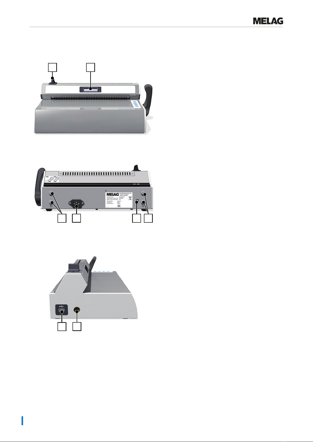
Views of the device..............................................................................................................................................................8
Symbols on the device.........................................................................................................................................................9
Menu structure...................................................................................................................................................................10
Status display and acoustic signals...................................................................................................................................11
4 Commissioning...................................................................................................................................................................12
Requirements of the installation location...........................................................................................................................12
Space requirements...........................................................................................................................................................12
Connecting the sealing device...........................................................................................................................................13
Switching on the sealing device.........................................................................................................................................13
5 Sealing.................................................................................................................................................................................14
Sealing procedure with pre-finished film pouches .............................................................................................................14
Sealing procedure for film reels.........................................................................................................................................15
6 Logging ...............................................................................................................................................................................18
Documenting the sealing process......................................................................................................................................18
Using the USB flash drive as an output medium ...............................................................................................................18
Computer as output medium .............................................................................................................................................19
Structure of the log files.....................................................................................................................................................19
7 Function checks .................................................................................................................................................................21
Function check with MELAcontrol Seal Check ..................................................................................................................21
8 Settings ...............................................................................................................................................................................23
Access settings menu........................................................................................................................................................23
Time...................................................................................................................................................................................23
Date ...................................................................................................................................................................................24
Sealing temperature ..........................................................................................................................................................24
Signal tones.......................................................................................................................................................................25
User administration............................................................................................................................................................25
Eco Mode and Standby .....................................................................................................................................................26
Force calibration ................................................................................................................................................................27
9 Maintenance........................................................................................................................................................................28
Cleaning and regular checks .............................................................................................................................................28
Maintenance ......................................................................................................................................................................28
Validation...........................................................................................................................................................................28
Software update.................................................................................................................................................................28

Contents
10 Pause times ......................................................................................................................................................................30
Pause times.......................................................................................................................................................................30
Transport and storage .......................................................................................................................................................30
11 Optional accessories .......................................................................................................................................................31
Reel dispenser Standard ...................................................................................................................................................31
Reel dispenser Comfort.....................................................................................................................................................31
Reel dispenser Deluxe.......................................................................................................................................................32
Wall mounted reel dispenser .............................................................................................................................................32
12 Malfunctions .....................................................................................................................................................................33
13 Manufacturer's recommendation for routine operation ...............................................................................................36
Performing the peel test.....................................................................................................................................................36
MELAG seal seam stability test.........................................................................................................................................36
14 Standard specifications...................................................................................................................................................37
15 Technical Data ..................................................................................................................................................................38
16 Accessories and spare parts ..........................................................................................................................................39

1 General guidelines
5
1 General guidelines
Please read this user manual carefully before commissioning the device. The manual includes important safety instruc-
tions. Make sure that you always have access to digital or printed version of the user manual.
Should the manual no longer be legible, is damaged or has been lost, you can download a new copy from MELAG down-
load centre at www.melag.com.
Symbols used
Symbol Explanation
Indicates a dangerous situation, which if not avoided, could entail slight to life-threatening
injuries.
Draws your attention to a situation, which if not avoided, could result in damage to the
instruments, the practice fittings or the device.
Draws your attention to important information.
Formatting rules
Example Explanation
Universal-
Program
Words or phrases appearing on the display of the device are marked as display text.
Prerequisites for the following handling instruction.
Refer to the glossary or another text section.
Information for safe handling.
Disposal
MELAG devices are synonymous with high quality and a long life-span. When you eventually need to decommission your
MELAG device, the required disposal of the device can take place with MELAG in Berlin. Simply contact your stockist.
Dispose of accessories and consumption media which you no longer require in the appropriate manner. Comply with all
relevant disposal specification in terms of possibly contaminated waste.
The packaging protects the device against transport damage. The packaging materials have been selected for their envi-
ronmentally-friendly disposability and can be recycled. Returning the packaging to the material flow reduces the amount
of waste and saves raw materials.

2 Safety
6
2 Safety
When operating the device, comply with the following safety instructions as well as those contained in
subsequent chapters. Use the device only for the purpose specified in these instructions. Failure to comply
with the safety instructions can result in injury and/or damage to the device.
Qualified personnel
nOnly competent and trained personnel may use the device.
nThe operator must ensure that the users are regularly trained in the operation and safe handling of the device.
Setup, installation and commissioning
nCheck the device after unpacking for any damage suffered during transport.
nThe device is not suitable for operation in explosive atmospheres.
nInstall and operate the device in a frost-free environment.
nThe device is conceived for use outside the patient area. The device should be located a minimum of 1.5m radius
away from the treatment area.
Power cable and power plug
nOnly the power cable included in the scope of delivery may be connected to the device.
nThe power cable may not be replaced by a cable determined to be insufficient.
Danger of short circuit
nLiquids may not be permitted to reach the interior of the device. This could result in an electrical shock or short circu-
iting.
Repair
nNever open the device housing. Incorrect opening and repair can compromise electrical safety and pose a danger to
the user. The guarantee and warranty are forfeited as soon as the device is opened by anyone other than a MELAG-
authorised technician.

3 Description of the device
7
3 Description of the device
Intended use
This sealing device is designed for application in a medical context, e.g. clinics and medical and dental practices. It was
developed especially for the heat sealing of instruments in sterilization packages and complies with the stand-
ardENISO11607-2 and the German standard DIN1)58953-7.
The bar sealing device MELAseal 200 is not a medical device as defined by the Medical Device Regulation.
Suitable materials
For the heat sealing of transparent sterilization packages in accordance with EN868-5 e.g. MELAfol reels and pouches
are suitable. Should you wish to use any other packaging materials, please consult your stockist or contact MELAG di-
rectly.
Unsuitable materials
Sterilization package that is not compatible with the requirements of EN868-5, is incompatible with this device. The
following materials are not suitable:
▪ Pure hose film (double-sided film), as these tends to become adhere to the sealing rail, and can restrict the
functionality of the sealing device.
▪ Polyethylene film
▪ Soft PVC film
▪ Hard PVC film
▪ Polyamide film
▪ Polypropylene film
NOTICE
The use of unsuitable packaging materials carries the risk of damage to or malfunction of the device.
nComply with the manufacturer’s recommendations for the sealing temperatures suitable for each type of
packaging material.
Scope of delivery
Please check the scope of delivery before setting up and connecting the device.
Standard scope of delivery
▪ Sealing device MELAseal 200
▪ User manual
▪ Checklist for installation and record of installation
▪ Declaration of conformity
▪ Warranty certificate
▪ Test and calibration protocol
▪ Power cable
▪ Sealing lever
▪ MELAG USB flash drive
1) DIN=Deutsches Institut für Normung

3 Description of the device
8
Views of the device
View from front
12
1 Knife handle
2 Display with control lamp
View from rear
3453
3 Bracket for reel dispenser
4 Power cable connection
5 USB interface (type B) for connection to
the computer
View from left
67
6 USB interface for the USB flash drive
7 Square hole for sealing lever (on both
sides)

3 Description of the device
9
View from right
10
9
8
8 Power switch (On/Off)
9 Sealing lever
10 Operating keys
Symbols on the device
Type plate
Manufacturer of the product
Date of manufacture of the product
REF
Article number of the product
SN
Serial number of the product
Observe user manual or electronic user manual
Do not dispose of product in household waste
CE marking
Electrical connection of the product: Alternating current (AC)
Symbols on the power switch
Switching on device
Switching off device

3 Description of the device
10
Menu structure
├Standard display output Key
│ └ 180°C/User 1/Ready Temperature/User/Operational readiness
├User User
│ ├ User 01 User 01
│ ├ User 02 User 02
├ ├ User... User...
│ └ User 10 User 10
├Seal chk Function check with MELAcontrol Seal Check
│ ├ approve? Performing function check with seal check
│ └ reminder Activate reminder for seal check
│ ├ weekly Weekly
│ │ ├ Mon on Mondays
│ │ ├ Tue on Tuesdays
│ │ ├ … …
│ │ ├ Sun on Sundays
│ ├ daily daily
│ └ Off Deactivate reminder for seal check
├Settings Settings
│ ├ Temp Sealing temperature
│ ├ Tone Switch signal tones on/off
│ ├ Time Time
│ │ ├ Adjust Set current time
│ │ └ Auto_DST Autom. change from summer/winter time (CET)
│ ├ Date Date (TT-MM-JJ)
│ ├ Eco Mode Eco Mode
│ │ ├ On/Off Switch Eco mode on/off
│ │ ├ Wait Eco 1. Waiting time: Setting the Eco Mode
│ │ └ Wait Stby 2. Waiting time: Setting the standby
│ └ Adj Frc Force calibration
└Info Information
├ Seal Cnt Counter for the sealing procedures
├ Svc Date Date of the next service
├ Svc Cnt Counter until the next service
├ Version Software version
└ S/N Serial number
Pressing the key or repeatedly enables navigation to the ring menu. Pressing returns you to the next
highest menu level.

3 Description of the device
11
Status display and acoustic signals
Control lamp/acoustic
signal
Possible cause What you can do
LED illuminates orange
The sealing device is in the heating or
cooling phase.
Wait until the pre-set sealing temperature has
been reached.
LED flashes red,
warning signal sounds
The sealing lever is depressed during
the heating phase.
The sealing temperature has not yet
been achieved.
The sealing lever has been raised
early, despite the required sealing
duration not having been reached.
The sealing lever has not been raised,
despite the required sealing duration
having been completed.
Acknowledge the message with
OK
and wait
until the LED control lamp illuminates green
continuously.
Acknowledge the message with
OK
and leave
the sealing lever depressed during sealing until
the message Open is issued.
Raise the sealing lever as soon as the display
notification Open is issued, otherwise the sealing
procedure will not be completed successfully.
NOTICE!Failure to observe these provisions
can result in the melting of the transparent
sterilization package and damage to the
sealing device.
LED illuminates green
The sealing device has reached the
pre-set sealing temperature and is
ready for operation.
The minimum sealing duration has
been reached and the sealing
procedure has been ended.
Raise the sealing lever and remove the
transparent sterilization packages.
LED flashes green
The sealing lever is depressed and the
sealing procedure runs. The progress
bar is displayed.
Wait until the green LED control lamp is
continuously illuminated or the display shows
Open.
LED flashes red,
warning signal sounds
(malfunction)
Device malfunction: The heating phase
takes too long (>5min). The sealing
device does not reach the pre-set
sealing temperature.
Switch off the sealing device and then on again.
Upon repeated occurrence, inform an authorised
technician.

4 Commissioning
12
4 Commissioning
See also “Installation and Set-up”.
Video tutorial
Requirements of the installation location
CAUTION
Failure to comply with the set-up conditions can result in injuries, malfunctions and/or damage to the
device.
nComply with all the specifications of this chapter for initial commissioning.
nThe device is not suitable for operation in explosive atmospheres.
nThe device is only intended for use in interior spaces.
nThe device is conceived for use outside the patient area. The device should be located a minimum of 1.5m radius
away from the treatment area.
nInstall the device in a dry and dust-protected location.
nMaintain sufficient clearance to the surrounding surfaces in order to ensure sufficient ventilation.
nEnsure that the sealing device is located away from direct sunshine and outside the range of other sources of heat.
nSet-up the device protected against blows or vibrations.
Space requirements
View from the front and right
Device dimensions MELAseal 200
Width A 36.5 cm
Width including sealing lever A141.5 cm
Height B 15 cm
Minimum clearance above B125 cm
Minimum clearance to the side C 10 cm
Minimum clearance to rear C18 cm
Depth D 24 cm
When using film reels, additional space is required for a reel dispenser e.g. the Reel dispenser Standard or Reel dis-
penser Deluxe.

4 Commissioning
13
Connecting the sealing device
üThe sealing device has been switched off.
üThe power cable, delivered in the scope of delivery, is present.
1. Connect the IEC plug of the power cable to the rear side of the
sealing device and connect the power plug in the power socket.
2. Insert the sealing lever in the square hole on the right or left hand
side of the device as required.
Switching on the sealing device
üThe sealing device is connected to the power supply.
üThe USB flash drive is connected for documentation purposes.
uSwitch on the sealing device at the power switch.
ÊAfter activation, the display issues system information. These are e.g. the user set, confirmation as to whether the
USB flash drive is connected correctly and the current temperature.
ÊThe control lamp on the fore side of the sealing device will illuminate orange. The sealing device is heated to the pre-
set temperature.
Operational readiness
The sealing device is ready for operation as soon as the pre-set sealing temperature has been reached, the display
shows Ready and the control lamp illuminates continuously green.

5 Sealing
14
5 Sealing
See also “Wrapping Instruments”.
Video tutorial
Sealing procedure with pre-finished film pouches
CAUTION
Danger of burns from hot metal parts. The sealing rail is heated continuously when the sealing device
is switched on.
nNever touch the metal surfaces on the sealing rail or in the area of the rear and fore paper guide.
NOTICE
Inserting the packaging inverted can result in the adhesion of film residue to the sealing rail.
The film side of the packaging must always face upwards.
PLEASE NOTE
When sealing MELAfol pouches with a side gusset, ensure compliance with the manufacturer’s
specifications (e.g. Instructions for handling MELAfol pouches with side gusset) especially when
wishing to seal cassettes.
In order to perform a sealing procedure with pre-finished film pouches, proceed as follows:
1. Insert the packaging (film side facing upwards) from the front in the
paper guide between the pressure rail and sealing rail. Ensure the
correct clearance between instrument and seal seam (see Standard
specifications [}page37]).
2. Press the sealing lever down until it latches.

5 Sealing
15
3. Leave the sealing lever depressed as long as the progress bar in
the display completes and the control lamp flashes green at short
intervals (approx. 3s).
4. When the display switches to Open and the control lamp is
continuously illuminated green, raise the sealing lever to its starting
position. Remove the film pouch from the sealing device.
ÊIf the USB flash drive has been connected, a log will
automatically be generated and saved on the USB flash drive.
ÊIf a USB flash drive has not been connected, the most
important sealing parameters will be displayed alternately up
to four times. Then the display switches to Ready.
5. Perform a visual inspection of the seal seam after every
successful sealing procedure.
PLEASE NOTE
With pouches with side gussets, perform weekly checks of the seal seam using an ink test (e.g.
MELAcontrol Ink Test).
Sealing procedure for film reels
Producing a film pouch
If the instruments are packaged in pouches from the reel in transparent sterilization packaging, proceed as follows:
1. Guide the end of the film reel along the device rear panel into the
lower paper guide with the paper side facing downwards (lower
slit). Slide the film forward between the pressure and sealing rail up
to the desired length.
2. Press the sealing lever down until it latches.

5 Sealing
16
3. Leave the sealing lever depressed as long as the progress bar in
the display completes and the control lamp flashes green at short
intervals (approx. 3s).
4. Cut of the film roll during the sealing procedure. Leave the sealing
lever depressed and move the handle of the knife to the other end of
the sealing device quickly. Do not return the knife handle.
5. When the display switches to Open and the control lamp is
continuously illuminated green, raise the sealing lever to its starting
position. Remove the film pouch from the sealing device.
Sealing film pouches
NOTICE
Inserting the packaging inverted can result in the adhesion of film residue to the sealing rail.
The film side of the packaging must always face upwards.
To seal the film pouch cut to the corresponding length, proceed as follows:
1. Place the instruments to be sterilized in the film pouch. Ensure the
correct clearance between instrument and seal seam (see Standard
specifications [}page37]).
2. Slide the open side of the film pouch from the front into the paper
guide.

5 Sealing
17
3. Press the sealing lever down until it latches.
4. Leave the sealing lever depressed as long as the progress bar in
the display completes and the control lamp flashes green at short
intervals (approx. 3s).
5. When the display switches to Open and the control lamp is
continuously illuminated green, raise the sealing lever to its starting
position. Remove the film pouch from the sealing device.
ÊIf the USB flash drive has been connected, a log will
automatically be generated and saved on the USB flash drive.
ÊIf a USB flash drive has not been connected, the most
important sealing parameters will be displayed alternately up
to four times. Then the display switches to Ready.
6. Perform a visual inspection of the seal seam after every
successful sealing procedure.

6 Logging
18
6 Logging
Documenting the sealing process
See also “Documentation and User Administration”.
Video tutorial
ENISO11607-2 requires that the sealing process is monitored and documented in order to satisfy the requirement for
compliance with the specifications contained in part 2 of the standard. As a result, you are able to record the logs of the
sealing procedures, to output and archive them on the following output media:
▪ USB flash drive
▪ Computer with documentation software e.g. MELAview/MELAtrace from software version 3.6
If a computer or USB stick is not connected, the most important sealing parameters can also be
documented by hand. The sealing parameters are displayed alternately up to four times.
Using the USB flash drive as an output medium
NOTICE
Danger of data loss through damage of the USB flash drive following improper use.
nDo not exert any force on the USB flash drive whilst inserting it.
Should you wish to save the log of a sealing procedure on the USB flash drive automatically, connect it as follows:
1. Switch off the sealing device.
2. Insert the USB flash drive in the USB interface on the left-hand side
of the sealing device.
3. Switch on the sealing device.
ÊAs soon as the USB flash drive has been recognized and is ready for operation, the display shows Mem_Conn
(=memory connected).
Comply with the following general information relating to logging with the USB flash drive:
nAlways switch off the sealing device before connecting or removing the USB flash drive.
nIf the USB flash drive has been reformatted, it must be issued with a name.
nCopy the log files from the USB flash drive to the computer at regular intervals.
nSelect only a single logging type, either by USB flash drive or via the documentation software MELAtrace/
MELAview. Otherwise, this can result in a failure to recognize that the output media has been disconnected, which
can result in data loss.
nDo not save any further non device-relevant files on the USB flash drive.

6 Logging
19
Computer as output medium
üThe computer is equipped with an USB port.
üThe MELAG USB driver is installed on the computer.
üThe sealing device is connected to the computer via a USB cable (optionally available).
üFirmware 1.12 requires MELAview Docu/MELAtrace version 3.0.15.1.
üFirmware 2.10 and above requires MELAview Docu/MELAtrace from version 3.6.2.1.
1. Install the MELAseal 200 PC driver on your computer. Download the
driver from the MELAG website (Service/Download Center).
2. Connect the type B USB cable to the rear panel of the sealing
device and connect the other end to the computer.
3. Establish a connection between the documentation software and
the sealing device and determine the folder in which the logs are
to be archived. Further information relating to the operation of the
sealing device with the documentation software can be found in
the corresponding user manual.
PLEASE NOTE
The daily log is continued even if the sealing device is switched on and off once; i.e. a new daily log is
not started.
Structure of the log files
The log is stored in HTML format (in English). The file name consists of the actual date, the serial number of the sealing
device and the total counter. A log includes all printing procedures of one day. A row in the log is written for every sealing
procedure.
20130723_132000901_0000095.htm
Date Serial number Total counter
A successful sealing procedure is marked with “OK” in the respective log row. If a malfunction occurs during a sealing
procedure, this is recorded in the log by an event number, e.g. F4. The corresponding fault value (e.g. sealing tempera-
ture, sealing force) will, depending on the nature of the malfunction, be displayed in square brackets or no value will be
displayed.

6 Logging
20
Example of a log with several sealing procedures:
Key:
Row 10 - Designation of the sealing device
Row 15 - Date of sealing procedure
Row 20 - Serial number of the sealing device
Row 25 - Software version installed
Row 30 - Total operating hours
Row 35 - Date of the next maintenance
---------- --------------
Stat - OK: Sealing procedure successful
- F03: Event number/sealing duration too short
Time - Time of the sealing procedure
Dur - Sealing duration
Temp - Sealing temperature (in °C)
Force - Sealing force (in N), with which the packaging was sealed
Limits - The threshold ranges of the sealing duration (Dur), sealing temperature (Temp) and sealing force
(Force)
Usr - User
SCnt - Daily batch counter for sealing procedures
SvcCnt - Number of sealing procedures until next maintenance
TtlCnt - Total number of sealing procedures
CS - Coded proof of authenticity
S/N - Serial number of the sealing device
Op. Hrs. - Total of previous operating hours
Other manuals for MELAseal 200
3
This manual suits for next models
1
Table of contents
Other MELAG Food Saver manuals