Meltric DXN Series User manual

Meltric Corporation
4640 Ironwood Drive
Franklin, WI 53132
(800)433-7642
www.meltric.com
GENERAL
Meltric’s DXN Series plugs & receptacles are
designed and rated for use in hazardous environments
where explosive gases or dusts may be present.
The DXN receptacle has a dead front, which iso-
lates the supply contacts and prevents user expo-
sure to live parts. The safey shutter blocking
access to the contacts can be opened only by DXN
plugs with compatible ratings and contact configu-
rations.
DXN’s that are equipped with optional auxiliary
contacts can be electrically interlocked with motor
controllers or other devices when the auxiliary con-
tacts are used as pilot contacts.
RATINGS & CERTIFICATIONS
To ensure the safe use of this product, the installer
must verify that the product is properly rated for the
application.
Electrical
The amperage and voltage ratings are indicated on
the device labels.
Hazardous Duty
DXN plugs & receptacles have both ATEX and
cCSAus ratings for use in hazardous environments.
ATEX – Class 1 Zone 1 AEx ed IIC T6
This rating certifies the product for use in surface
(non-underground) applications where a high level
of protection is required and where the presence of
an explosive atmosphere of any type of gas or dust
is likely to occur. The associated maximum surface
temperature of the product is 85°C, at an ambient
temperature of 40°C.
cCSAus – Class 1 Division 2 Group A, B, C, D
Class 2 Division 2 Group E, F, G
This rating certifies the product for use in applica-
tions where flammable gases, such as Acetylene,
hydrogen, ethylene or propane, or dusts, such as
magnesium, coal or grain, may be present under
abnormal conditions.
Ingress Protection
DXN’s have an IP 66/67 rating for protection
against ingress of water, dust and other matter. IP
66 provides total protection against dust and water
jets. IP 67 adds protection for temporary immer-
sion in shallow water.
These ratings apply when the plug and receptacle
are mated. They also apply to the receptacle
alone, provided that its lid is latched in the closed
position. Optional plug caps are available for pro-
viding IP 66/67 protection on unmated plugs.
INSTALLATION
DXN’s must be used in conjunction with other
appropriately rated hazardous duty products and
must be installed by qualified electricians in accor-
dance with all applicable local and national electri-
cal codes. Before starting, ensure that the power
is off and verify that the conductors meet the
requirements of the National Electric Code and are
within the capacities of the DXN terminals noted in
Table 1.
Other sizes may be used in
conjunction with appropriate wiring ferrules.
Assembly for In-line Connections
When DXN’s are used as in-line connectors, finger
drawplates should be installed on both the receptacle
and plug in order to more easily provide the leverage
required to properly connect the devices.
Adjust the bushing diameter to fit the cable by
removing inner sections of it as required. Loosely
re-assemble the compression nut, bushing and
strain relief to the threaded adapter on the end of
the handle and insert the cable through it, the thin
black drawplate gasket and finger drawplate (if
applicable), and the color-coded gasket. Being
mindful that the strain relief must clamp on the
cable sheath, strip the cable sheath as required to
provide a workable wire length. Then strip the individ-
ual wires to the lengths indicated in Table 2, and
twist the strands of each conductor together.
Back out the terminal screws on the receptacle (or
inlet) far enough (but not completely) to allow the
conductors to pass, insert the conductors fully into
their respective terminals and tighten the terminal
screws with a hand screwdriver to the torque indi-
cated in Table 3.
DXN terminals are spring assisted to prevent
loosening due to strand settlement, vibration and
thermal cycling. Do not over-tighten.
Verify that the cable sheath will extend beyond the
strain relief and into the handle. Assemble the
receptacle (or inlet), the color-coded gasket, the
finger drawplate,and the thin black finger drawplate
gasket to the handle with the four self-tapping
screws provided. (CAUTION – over-tightening
the screws may cause cracking in polymeric com-
ponents). Adjust the cable location so that it will
not be under tension inside the handle and tighten
the compression nut to secure the cable.
Assembly for Mounted Receptacles
(or Inlets)
In applications where DXN receptacles (or inlets)
are mounted to wall boxes, panels or other equip-
ment, optimal operation is achieved when the
device is installed with the latch at the top.
NOTE: If the device is mounted to a wall box,
make sure that appropriate hole plugs are securely
tightened in any unused connection holes.
Insert the cable or wires through the wall box and
cut to allow adequate length, strip the cable
sheath, as desired, strip the individual wires to the
lengths indicated in Table 2, and twist the strands
of each conductor together. Back out the terminal
DXN1 10.6 in-lbs 1/8” precision tip
DXN3 (Main Contacts) 10.6 in-lbs 3/16” precision tip
DXN3 (Aux. Contacts) 10.6 in-lbs 1/8” precision tip
DXN6 (Main Contacts) 22.0 in-lbs 3/16” precision tip
DXN6 (Aux. Contacts) 10.6 in-lbs 1/8” precision tip
OPERATING INSTRUCTIONS
DXN
Table 1 - Conductor Size Capacity - AWG
Main Contacts Aux. Contacts
Max Min Max Min
DXN1 10 20 - -
DXN3 8 14 12 20
DXN6 3 10 12 20
Table 3 - Recommended Tightening Torques
Terminal Torque Flat Screwdriver
Compression
Nut
Handle
Strain
Relief Color-Coded
Gasket
Receptacle
(or Inlet)
Bushing
Threaded
Adapter
Finger Drawplate Gasket
Finger Drawplate
Issued: 04/15/2005Rev. A
Inches mm
DXN1 - All 0.50 12
DXN3 - Main 0.75 20
DXN3 - Aux. 0.75 17
DXN6 - Main 0.75 20
DXN6 - Aux 0.75 18
Table 2 - Wire Strip Length - A
Coutesy of Gross Automation 1724 South Johnson Road New Berlin, WI PH: 262-446-0000 FAX: 262-446-0300 www.meltricsales.com

screws on the receptacle (or inlet) far enough (but
not completely) to allow the conductors to pass,
insert the conductors fully into their respective ter-
minals and tighten the terminal screws to the
torque indicated in Table 3, with a hand screwdriver.
Assemble the receptacle (or inlet) and the color-
coded gasket to the box with appropriate hardware.
(CAUTION –over-tightening the screws may
cause cracking in polymeric components).
Assemble the mating plug (or receptacle) to the
cord end as indicated in the assembly instructions
above for in-line connections, except there will be
no finger drawplate or associated black gasket.
In cases where custom mounting is being per-
formed to an appropriate hazardous duty box or
panel, the clearance and mounting holes should be
drilled as indicated in the following diagram.
Hole Pattern for Custom Mounting
In order to maintain IP66/67 protection in custom
installations, watertight seals must be used under
the heads of the four mounting bolts and they must
be retained by a lock washer and nut on the inside
of the box or panel. Alternatively, four blind holes
can be drilled and threaded to accommodate #8-32
x5/8” mounting screws. The hole depth must be
sufficient to achieve adequate gasket compression.
OPERATION
To ensure safe and reliable operation, Meltric plugs
and receptacles must be used in accordance with
their assigned ratings. They can only be used in
conjunction with mating receptacles or plugs man-
ufactured by Meltric or another licensed producer
of products bearing the trademark.
Meltric plugs & receptacles are designed with dif-
ferent keying arrangements, so that only plugs and
receptacles with compatible contact configurations
and electrical ratings will mate with each other.
Connection
To connect a plug and receptacle, first depress the
pawl to open the lid on the receptacle, then orient
the plug 1 so that the red dot on the outside of the
casing lines up with the red dot just to the left of the
latch on the receptacle casing. Push the plug partially
into the receptacle until it hits a stop, then rotate the
plug in the clockwise direction until it hits another
stop after about 30° of rotation. At this point, the
circuit is still open. Push the plug straight into the
receptacle 2 until it becomes securely latched in
place. The connection is now made. On in-line
connectors, squeeze the drawplates on both sides
of the device together until the plug latches in place.
Disconnection
To break the connection, depress the pawl and
simultaneously pull the plug straight out 3 to the
rest position. The circuit is broken. To withdraw
the plug, simply rotate it counter-clockwise (about
30°) until it releases from the receptacle 4. Close
and latch the lid on the receptacle.
Partial Compatibility with the DSN Series
All DXN1 plugs and DXN3 plugs without auxiliary
contacts are compatible with similarly rated Meltric
DSN1 and DSN3 series receptacles for non-haz-
ardous locations. This allows hazardous location
equipment to additionally be used in non-haz-
ardous areas. DXN6 plugs do not have similar
compatibility with DSN6 receptacles.
Lockout Provisions
All DXN plugs are provided with lockout provisions.
To lockout the plug, insert the locking device
through the hole provided in the casing. This will
prevent the plug from being able to be inserted into
areceptacle.
DXN’s may also be purchased with optional lockout
provisions for the receptacle. To lockout the receptacle,
close and latch the lid and then attach the locking
device through the hole provided in the latch. This
will prevent the lid from being opened.
NOTE: Attaching the receptacle locking device
with the lid open will not prevent the insertion of a
plug. Lockout is only accomplished when the lid is
locked closed.
MAINTENANCE
Meltric products require little on-going maintenance.
However, it is a good practice to periodically per-
form the following general inspections:
• Check the mounting screws for tightness.
• Verify that the weight of the cable is
supported by the strain relief mechanism
and not by the terminal connections.
•Check the IP gaskets for wear and resiliency.
Replace as required.
• Verify the electrical continuity of the
ground circuit.
• Check the contact surfaces for cleanliness
and pitting.
Deposits of dust or similar foreign materials can be
rubbed off the contacts with a clean cloth. Sprays
should not be used, as they tend to collect dirt. If
any significant pitting of the contacts or other seri-
ous damage is observed, the device should be
replaced.
MANUFACTURER’S RESPONSIBILITY
Meltric’s responsibility is strictly limited to the repair
or replacement of any product that does not conform
to the warranty specified in the purchase contract.
Meltric shall not be liable for any penalties or con-
sequential damages associated with the loss of
production, work, profit, or any other kind of financial
loss incurred by the customer.
Meltric Corporation shall not be held liable when its
products are used in conjunction with products not
bearing the trademark. The use of Meltric
products in conjunction with mating devices that
are not marked with the trademark shall
void all warranties on the product.
Meltric Corporation is a member of the international
association, BECMA: the Butt-contact Electrical
Connectors Manufacturers Association.
1
2
3
4
DXN1: 1.656”
(42mm)
DXN3: 1.890”
(48mm)
DXN6: 2.171”
(55.2mm)
DXN1: 2.00”
(51mm)
DXN3: 2.25”
(56mm)
DXN6: 2.50”
(64mm)
DXN1: 1.656” (42 mm)
DXN3: 1.890” (48 mm)
DXN6: 2.171” (55.2 mm)4 x Ø.196
(#9 or 5mm)
CUSTINFO/DXN
Coutesy of Gross Automation 1724 South Johnson Road New Berlin, WI PH: 262-446-0000 FAX: 262-446-0300 www.meltricsales.com
This manual suits for next models
3
Other Meltric Cables And Connectors manuals
Meltric
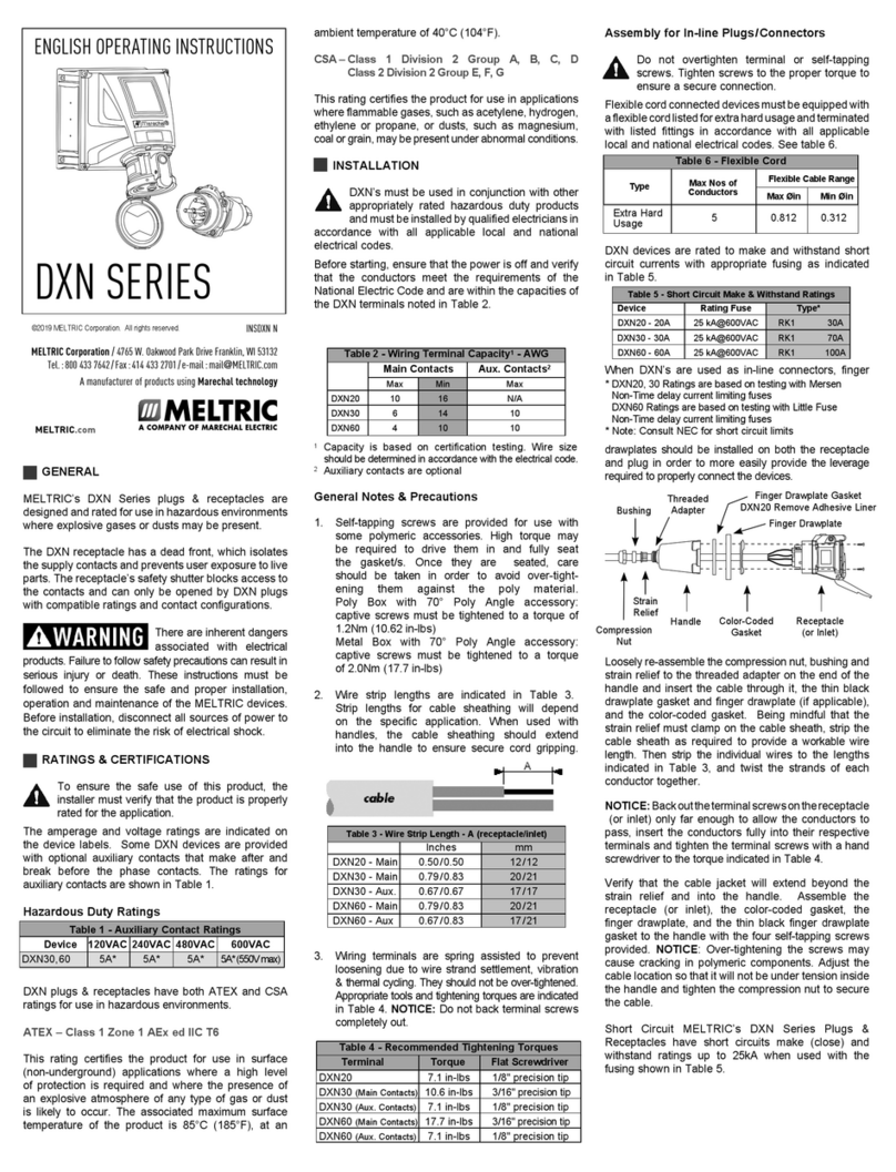
Meltric DXN30 User manual
Meltric
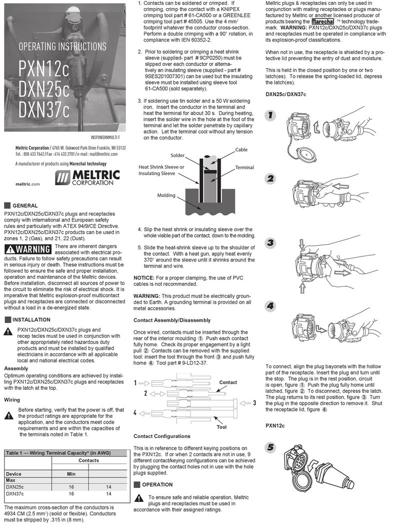
Meltric PXN12c User manual
Meltric
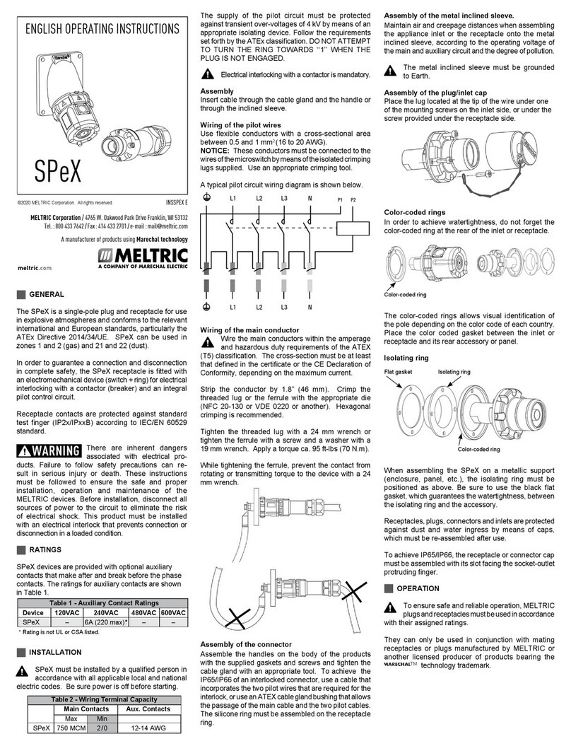
Meltric SPeX User manual
Meltric
Meltric DN9C User manual
Meltric
Meltric PN12c User manual
Meltric
Meltric CS1000 User manual
Meltric
Meltric DSDC Series User manual
Meltric
Meltric RETTBOX S User manual
Meltric
Meltric DS Series User manual
Meltric
Meltric DR Series User manual
