mcr FID 240 single-blade fire dampers
“MERCOR” SA – The company reserves the right to modify and change the document. Version FID 240 21.07.29.1 5/19
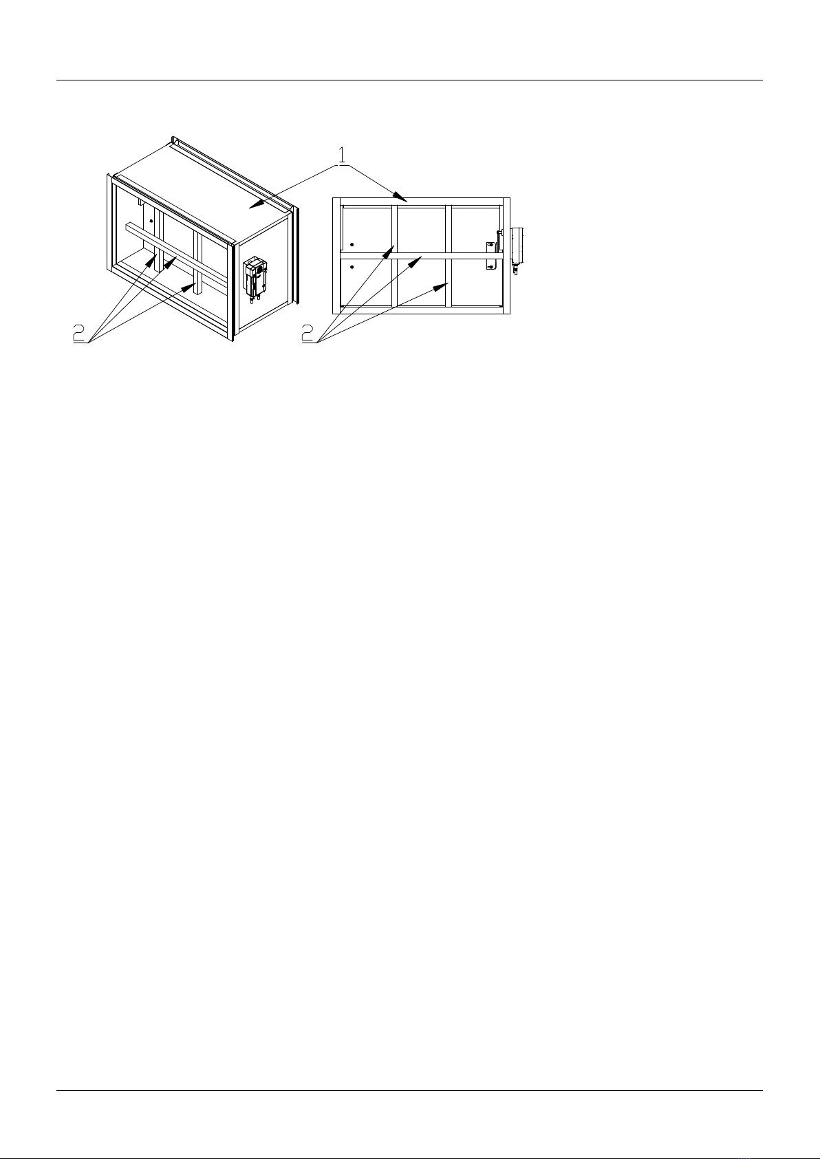
4. DESIGN AND OPERATING PRINCIPLE
Design
The mcr FID 240 single-blade fire dampers comprise a casing with a rectangular cross-section, a moving
isolation partition and a trigger control gear which is tripped remotely or automatically by tripping a thermal
trigger. The damper casing and moving isolation partition is made of fire-proof panel. The isolation partition
is set in a reinforcement profile made of metal sheet. The inner side of the fire damper casing features a
intumescent gasket. There are stop shapes fastened to the inner casing surface and made offire-proof
panel, which limit the rotating motion of the isolation partition. The damper has both ends of body with
flanged connections.
Function
The operating principle and behaviour of the mcr FID 240/... single-blade dampers depend on their
application versions:
cut-off fire dampers – mcr FID 240 /S
In the normal operating position the dampers are open. The dampers are closed (to the safety
position) as follows:
automatically, by tripping the thermoelectric trigger
manually, by pressing the control button on the thermoelectric trigger
remotely, by tripping an electric axial actuator with a return spring caused by isolation from the
supply voltage
automatically, by tripping the thermal trigger and the driving spring
cut-off fire dampers for fire ventilation systems – mcr FID 240 /V
In the normal operating position the dampers are closed. The dampers are opened (to the safety
position) as follows:
remotely, by tripping an electric axial actuator without a return spring, as a result of applying the
supply voltage to the actuator in the right manner
remotely, by tripping the electromagnetic release and a spring as a result of applying the voltage
cut-off fire dampers for mixed fire ventilation systems – mcr FID 240 /V-M
In normal operation the dampers are closed or open, depending on the function carried out. The
dampers are opened/closed (to the safety position) as follows:
remotely, by tripping the electrical axial actuator without a return spring in order to apply supply
voltage to the actuator in the right manner
remotely, by tripping the electromagnetic release and a spring as a result of applying the voltage
transfer fire dampers – mcr FID 240 /T
In the normal operating position the dampers are open or closed. The dampers are switched to the
safety position as follows:
automatically, by tripping the thermoelectric trigger
manually, by pressing the control button on the thermoelectric trigger
remotely, by tripping an electric axial actuator with a return spring caused by isolation from the
supply voltage
automatically, by tripping the thermal trigger and the driving spring
relief fire dampers – mcr FID 240 /G
In normal operation the dampers are closed or open, depending on the function carried out. The
dampers are opened/closed (to the safety position) as follows:
remotely, by tripping an electric axial actuator with a return spring caused by isolation from the
supply voltage The actuator has no thermoelectric trigger.
It is possible to manually service check the proper performance of the dampers with electrical actuators
by placing a special hex wrench in the socket marked on the actuator and rotating it to set the damper
isolating partition in the relevant position. Rotate the wrench slowly, smoothly and carefully. Rotating the
wrench too fast or too rapidly may damage the internal actuator gear or the drive transmission system.
The mcr T2 tester is recommended to check the proper performance of dampers with electric actuators.