mcr FID B single-plane fire dampers
“MERCOR” SA – The company reserves the right to modify and change the document. Version FID B 21.07.30.02 5/22
Execution versions
mcr FID B dampers can be made as rectangular dampers.
Dimension type series
mcr FID B fire dampers are manufactured in the following size ranges:
Width: 200 to 1200 mm
Height: 200 to 800 mm
Width: 600 mm
Aside from the standard dimensions, the fire dampers may also be manufactured in intermediate sizes.
The damper casing can be made longer on request. Maximum surface area of type mcr FID B dampers:
0,96 m2. The minimum damper surface area is 0,04 m2.
4. DESIGN AND OPERATING PRINCIPLE
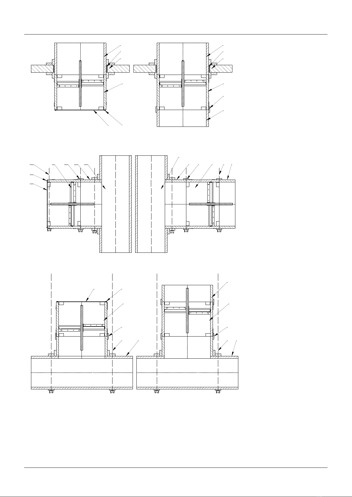
Design
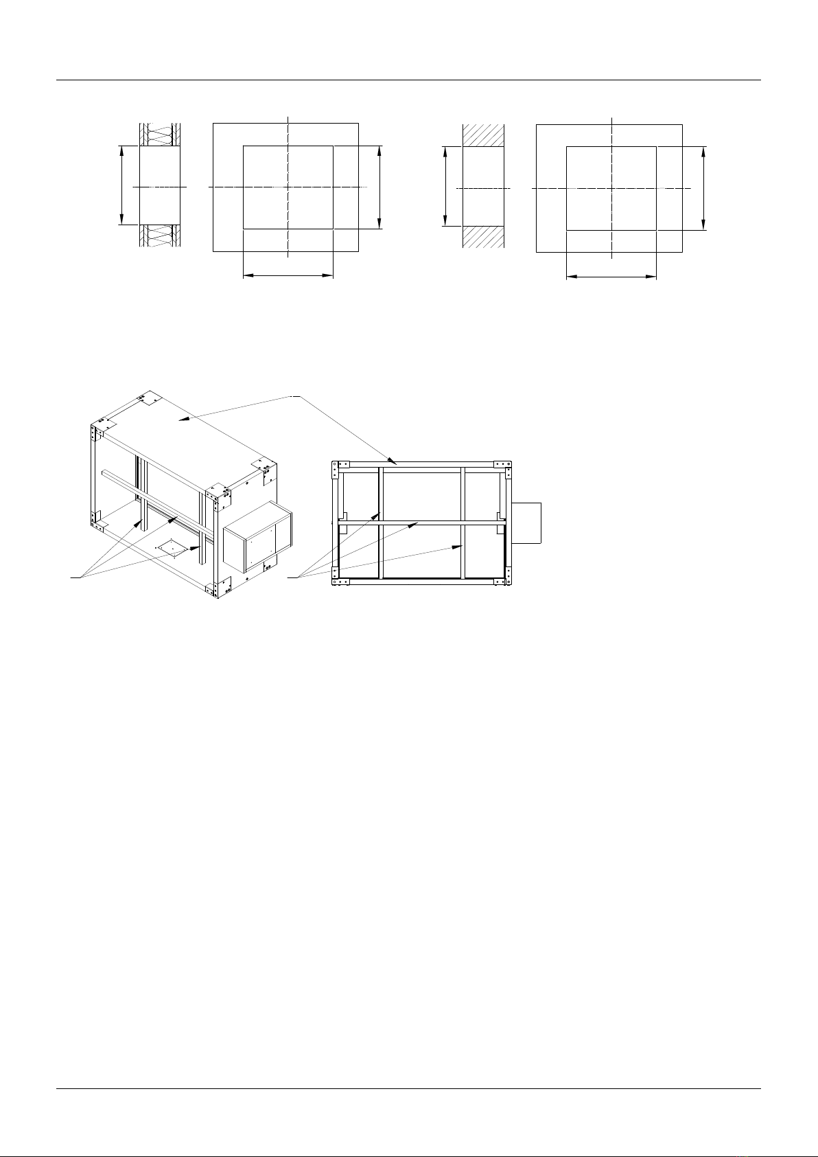
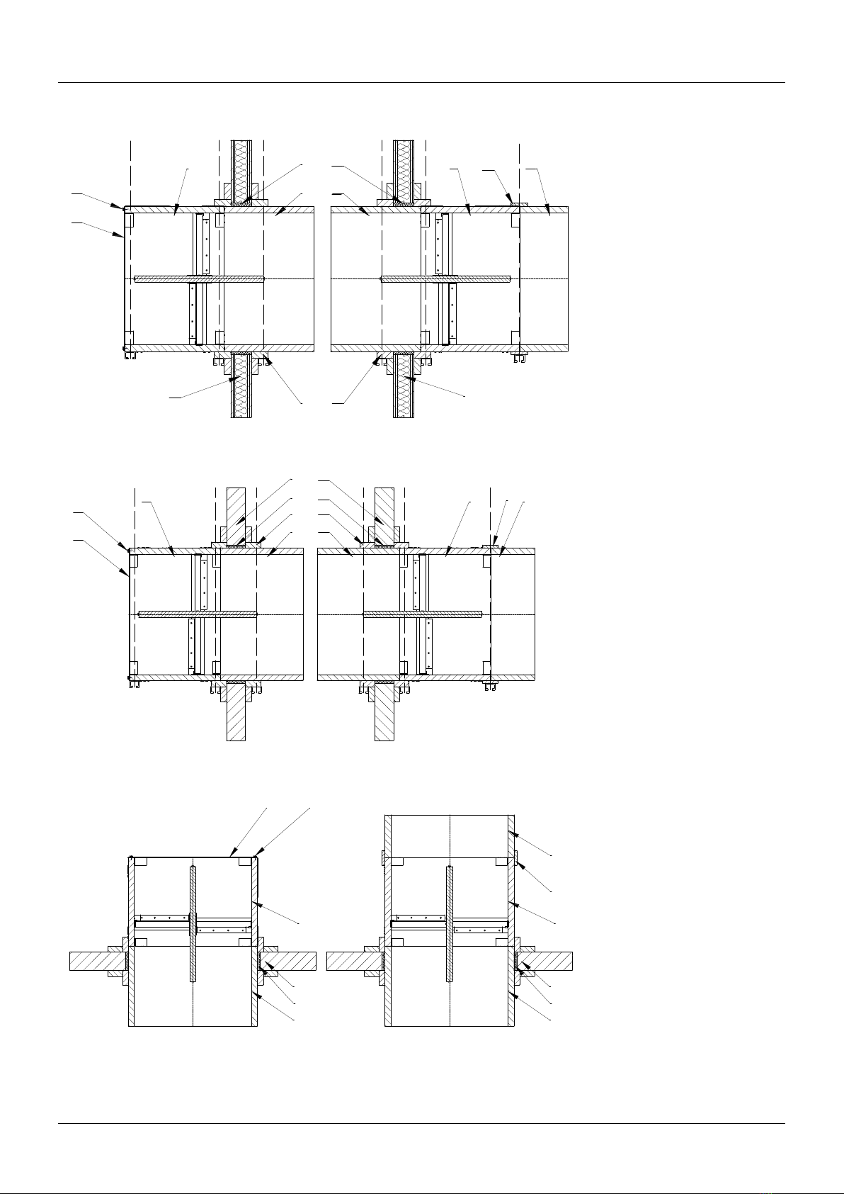
The mcr FID B dampers consist of a casing with a rectangular cross-section consisting of fireproof boards,
a movable cut-off partition and an actuator operated manually or remotely. The cut off partition of the
dampers is made of a fireproof boards and is set in a sheet-metal profile. There is a ventilation gasket on
the inside of the housing. Retaining sections made of fireproof boards are attached to the inner surface of
the housing, limiting the movement of the rotating partition. The sections are covered with a ventilation
gasket. Corners made of steel, galvanized or stainless steel are attached to the outer surface of the
housing in the corners. For chemically aggressive environments, special enclosures are used, where the
fireproof boards are impregnated.
Function
The operating principle and behaviour of the mcr FID B single-plane dampers depend on their application
versions:
cut-off fire dampers – mcr FID B/S
In the normal operating position the dampers are open. The dampers are closed (to the safety position)
as follows:
automatically, by tripping the thermoelectric trigger
remotely, by tripping an electric axial actuator with a return spring caused by isolation from the supply
voltage
automatically, by tripping the thermal trigger and the driving spring
cut-off fire dampers for fire ventilation systems – mcr FID B/V
In the normal operating position the dampers are open or close depending on the function. The dampers
are closed/ opened as follows:
remotely, by tripping an electric axial actuator without a return spring, as a result of applying the
supply voltage to the actuator in the right manner. The damper blade can change position without loss
of device functionality for 25 minutes from the time of activation of operation.
remotely, by tripping the electromagnetic release and a spring as a result of applying the voltage
cut-off fire dampers for mixed fire ventilation systems – mcr FID B/M
In the normal operating position the dampers are open or close depending on the function. The dampers
are closed/ opened as follows:
remotely, by tripping an electric axial actuator without a return spring, as a result of applying the
supply voltage to the actuator in the right manner. The damper blade can change position without loss
of device functionality for 25 minutes from the time of activation of operation.
remotely, by tripping the electromagnetic release and a spring as a result of applying the voltage