Mercury 2B User manual

B
2
51806
ELECTRICAL
BATTERY CHARGING SYSTEM
AND STARTING SYSTEM

2B-0 - ELECTRICAL 90-852396 MAY 1996
Table of Contents Page Page
Specifications 2B-1. . . . . . . . . . . . . . . . . . . . . . . . . . . .
Special Tools 2B-1. . . . . . . . . . . . . . . . . . . . . . . . . . . .
Battery 2B-2. . . . . . . . . . . . . . . . . . . . . . . . . . . . . . . . . .
Precautions 2B-2. . . . . . . . . . . . . . . . . . . . . . . . . . .
Specific Gravity Readings 2B-2. . . . . . . . . . . . . . . . .
Specific Gravity Cell Comparison Test 2B-3. . . .
Electrolyte Level 2B-3. . . . . . . . . . . . . . . . . . . . . . . . .
Charging a Discharged Battery 2B-3. . . . . . . . . . . . .
Winter Storage of Batteries 2B-4. . . . . . . . . . . . . . . .
Battery Charging System Description 2B-4. . . . . . .
Battery Charging System Troubleshooting 2B-5. . .
General Troubleshooting 2B-5. . . . . . . . . . . . . . .
Alternator System 2B-5. . . . . . . . . . . . . . . . . . . . .
Stator Test (Alternator Coils Only) 2B-5. . . . .
Troubleshooting Alternator System 2B-5. . . . . . .
Determining Cause Of Problem 2B-6. . . . . . .
Problem: Constant High Output 2B-6. . . . . . .
Problem: No Output 2B-6. . . . . . . . . . . . . . . . .
Regulation Voltage Check 2B-6. . . . . . . . . . . .
Voltage Regulator Test
(Using Ohm Meter) 2B-7. . . . . . . . . . . . . . . . . .
Removal of Voltage Regulator 2B-7. . . . . . . .
Installation of Voltage
Regulator/Rectifier 2B-7. . . . . . . . . . . . . . . . . .
Starter System 2B-8. . . . . . . . . . . . . . . . . . . . . . . .
Starter System Components 2B-8. . . . . . . . . .
Description 2B-8. . . . . . . . . . . . . . . . . . . . . . . . .
Troubleshooting The Starter Circuit 2B-8. . . .
Flywheel/Starter Assembly 2B-9. . . . . . . . . . . . . . . .
Starter Assembly 2B-10. . . . . . . . . . . . . . . . . . . . . . . .
Starter Circuit Troubleshooting
Flow Chart 2B-11. . . . . . . . . . . . . . . . . . . . . . . . . . .
Starter Removal and Installation 2B-12. . . . . . . .
Removal 2B-12. . . . . . . . . . . . . . . . . . . . . . . . . .
Installation 2B-13. . . . . . . . . . . . . . . . . . . . . . . .
Disassembly 2B-13. . . . . . . . . . . . . . . . . . . . . .
Starter Cleaning, Inspection and
Testing 2B-14. . . . . . . . . . . . . . . . . . . . . . . . . . . . . .
Cleaning and Inspection 2B-14. . . . . . . . . . . .
Testing 2B-14. . . . . . . . . . . . . . . . . . . . . . . . . . .
Starter Reassembly 2B-16. . . . . . . . . . . . . . . .
Starter Solenoid Test 2B-18. . . . . . . . . . . . . . .

ELECTRICAL - 2B-1
90-852396 MAY 1996
Specifications
Starter Draw (No Load) 40 Amperes
Starter Draw (Under
Load) 175 Amperes
Battery Rating 670 Marine Carnking
Amps (MCA)
or 520 Cold Cranking
Amps (CCA)
Alternator Output 12 Amperes @ 3000
RPM
Special Tools
Multi Meter DVA Tester 91-99750A1
Description Part Number
Hydrometer Obtain Locally
Ammeter Obtain Locally

2B-2 - ELECTRICAL 90-852396 MAY 1996
Battery
Precautions
WARNING
If battery acid comes in contact with skin or eyes,
wash skin immediately with a mild soap. Flush
eyes with water immediately and see a doctor.
When charging batteries, an explosive gas mixture
forms in each cell. Part of this gas escapes through
holes in vent plugs and may form an explosive atmo-
sphere around battery if ventilation is poor. This ex-
plosive gas may remain in or around battery for sev-
eral hours after it has been charged. Sparks or
flames can ignite this gas and cause an internal ex-
plosion which may shatter the battery.
The following precautions should be observed to pre-
vent an explosion.
1. DO NOT smoke near batteries being charged or
which have been charged very recently.
2. DO NOT break live circuits at terminals of batter-
ies because a spark usually occurs at the point
where a live circuit is broken. Always be careful
when connecting or disconnecting cable clamps
on chargers. Poor connections are a common
cause of electrical arcs which cause explosions.
3. DO NOT reverse polarity of battery terminal to
cable connections.
Specific Gravity Readings
Use ahydrometer to measure specific gravity of elec-
trolyte in each cell.
Hydrometer measures percentage of sulfuric acid in
battery electrolyte in terms of specific gravity. As a
battery drops from a charged to a discharged condi-
tion, acid leaves the solution and enters the plates,
causing a decrease in specific gravity of electrolyte.
An indication of concentration of electrolyte is ob-
tained with a hydrometer.
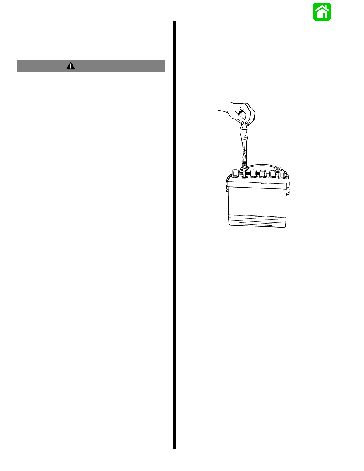
When using a hydrometer, observe the following
points:
1. Hydrometer must be clean (inside and out) to in-
sure an accurate reading.
2. Never take hydrometer readings immediately af-
ter water has been added. Water must be thor-
oughly mixed with electrolyte by charging for at
least 15 minutes at a rate high enough to cause
vigorous gassing.
3. If hydrometer has built-in thermometer, draw liq-
uid in several times to ensure correct tempera-
ture before taking reading.
4. Hold hydrometer vertically and draw in just
enough liquid from battery cell so that float is free-
floating. Hold hydrometer at eye level so that float
is vertical and free of outer tube, then take read-
ing at surface of liquid. Disregard curvature
where liquid rises against float stem due to capil-
larity.
22532
5. Avoid dropping electrolyte on boat or clothing, as
it is extremely corrosive. Wash off immediately
with baking soda solution.
Specific gravity of electrolyte varies not only with per-
centage of acid in liquid but also with temperature. As
temperature increases, electrolyte expands, so that
specific gravity is reduced. As temperature drops,
electrolyte contracts, so that specific gravity in-
creases. Unless these variations in specific gravity
are taken into account, specific gravity obtained by
hydrometer may not give a true indication of acid in
electrolyte.
A fully charged battery will have a specific gravity
reading of approximately 1.270 at an electrolyte tem-
perature of 80°F (27°C). If electrolyte temperature
is above or below 80°F, additions or subtractions
must be made in order to obtain a hydrometer read-
ing corrected to 80°F standard. For every 10°F (3.3°
C) above 80°F, add 4 specific gravity points (.004) to
hydrometer reading. Example: A hydrometer reading
of 1.260 at 110°F (43°C) would be 1.272 corrected
to 80°F, indicating a fully charged battery.
For every 10°below 80°F, subtract 4 points (.004)
from the reading. Example: A hydrometer reading of
1.272 at0°F (-18°C) would be 1.240 corrected to 80°
F, indicating a partially charged battery.

ELECTRICAL - 2B-3
90-852396 MAY 1996
SPECIFIC GRAVITY CELL
COMPARISON TEST
This test may be used when an instrumental tester is
not available. To perform this test, measure specific
gravity of each cell, regardless of state of charge, and
interpret results as follows: If specific gravity read-
ings show a difference between highest and lowest
cell of .050 (50 points) or more, battery is defective
and should be replaced.
Electrolyte Level
Check electrolyte level in battery regularly. A battery
in use in hot weather should be checked more fre-
quently because of more rapid loss of water. If elec-
trolyte level is found to be low, then distilled water
should be added to each cell until liquid level rises ap-
prox. 3/16 in. (4.8mm) over plate. DO NOT OVER-
FILL, because this will cause loss of electrolyte and
result in poor performance, short life and excessive
corrosion.
CAUTION
During service, only distilled water should be
added to the battery, not electrolyte.
Liquid level in cells should never be allowed to drop
below top of plates, as portion of plates exposed to
air may be permanently damaged with a resulting
loss in performance.
Charging a Discharged
Battery
The following basic rules apply to any battery charg-
ing situation:
1. Any battery may be charged at any rate (in am-
peres) or as long as spewing of electrolyte (from
violent gassing) does not occur and for as long as
electrolyte temperature does not exceed 125°F
(52°C). If spewing of electrolyte occurs, or if elec-
trolyte temperature exceeds 125°F, charging
rate (in amperes) must be reduced or temporarily
halted to avoid damage to the battery.
2. Battery is fully charged when, over a 2-hour peri-
od at a low charging rate (in amperes), all cells
are gassing freely (not spewing liquid electro-
lyte), and no change in specific gravity occurs.
Full charge specific gravity is 1.260-1.275, cor-
rected for electrolyte temperature with electrolyte
level at 3/16 in. (4.8mm) over plate, unless elec-
trolyte loss has occurred (from age or over-filling)
in which case specific gravity reading will be low-
er. For most satisfactory charging, lower charg-
ing rates in amperes are recommended.
3. If, after prolonged charging, specific gravity of at
least 1.230 on all cells cannot be reached, battery
is not in optimum condition and will not provide
optimum performance; however, it may continue
to provide additional service, if it has performed
satisfactorily in the past.
4. To check battery voltage while cranking engine
with electric starting motor, place RED (+) lead of
tester on POSITIVE (+) battery terminal and
BLACK (-) lead of tester on NEGATIVE (-) battery
terminal. If the voltage drops below 9-1/2 volts
while cranking, the battery is weak and should be
recharged or replaced.

2B-4 - ELECTRICAL 90-852396 MAY 1996
Winter Storage of Batteries
Battery companies are not responsible for battery
damage either in winter storage or in dealer stock if
the following instructions are not observed:
1. Remove battery from its installation as soon as
possible and remove all grease, sulfate and dirt
from top surface by running water over top of bat-
tery. Be sure, however, that vent caps are tight
beforehand, and blow off all excess water thor-
oughly with compressed air. Check water level,
making sure that plates are covered.
2. When adding distilled water to battery, be ex-
tremely careful not to fill more than 3/16 in. (4.8
mm) above perforated baffles inside battery. Bat-
tery solution or electrolyte expands from heat
caused by charging. Overfilling battery will cause
electrolyte to overflow (if filled beyond 3/16 in.
above baffles).
3. Grease terminal bolts well with 2-4-C Marine Lu-
bricant and store battery in a COOL-DRY place.
Remove battery from storage every 30-45 days,
check water level and put on charge for 5 or 6
hours at 6 amperes. DO NOT FAST CHARGE.
4. If specific gravity drops below 1.240, check bat-
tery for reason and recharge. When gravity
reaches 1.260, discontinue charging. To check
specific gravity, use a hydrometer, which can be
purchased locally.
5. Repeat preceding charging procedure every
30-45 days, as long as battery is in storage, for
best possible maintenance during inactive peri-
ods to ensure a good serviceable battery in
spring. When ready to place battery back in ser-
vice, remove excess grease from terminals (a
small amount is desirable on terminals at all
times), recharge again as necessary and reinstall
battery.
WARNING
Hydrogen and oxygen gases are produced dur-
ing normal battery operation or charging. Sparks
or flame can cause this mixture to ignite and ex-
plode, if they are brought near the vent openings.
Sulfuric acid in battery can cause serious burns,
if spilled on skin or in eyes. Flush or wash away
immediately with clear water.
Battery Charging System
Description
The battery charging system components are the fly-
wheel permanent magnets, stator, voltage regulator/
rectifier and battery. The rotating permanent mag-
nets induce an alternating current (AC) in the stator
coils. The AC current is rectified to direct current (DC)
by the voltage regulator/rectifier. The DC output from
the voltage regulator/rectifier is used to charge the
battery. The voltage regulator/rectifier also senses
the battery voltage as a measure of the battery’s
state of charge and thereby regulates the DC current
flow to the battery. In this manner, the battery charge
is maintained and the battery is protected from an
overcharge condition.
ab
c
d
e51806
a - Stator
b - Starter Solenoid
c - To Tachometer
d - Voltage Regulator/Rectifier
e - 12 Volt Battery

ELECTRICAL - 2B-5
90-852396 MAY 1996
Battery Charging System
Troubleshooting
General Troubleshooting
A fault in the battery charging system will usually
cause the battery to become UNDERCHARGED. A
defective VOLTAGE REGULATOR may also allow
the system to OVERCHARGE the battery.
If a problem exists in the charging system, visually
check the following:
1. Check for correct battery polarity [RED cable to
(+) POSITIVE battery terminal].
2. Check for loose or corroded battery terminals.
3. Check condition of the battery.
4. Visually inspect all wiring between stator and bat-
tery for cuts, chafing and disconnected, loose or
corroded connections.
5. Excessive electrical load (from too many acces-
sories) will cause battery to run down, even if the
system is operating correctly.
If the system is still OVERCHARGING the battery,
the VOLTAGE REGULATOR is most likely defective
and should be replaced.
If the battery is UNDERCHARGED, proceed with
REGULATOR, STATOR, and RECTIFIER tests, fol-
lowing.
Alternator System
STATOR TEST (ALTERNATOR COILS ONLY)
NOTE: Stator can be tested without removing from
engine.
1. Disconnect 2 YELLOW stator leads from bullet
connectors to voltage regulator/rectifier.
2. Use an ohmmeter and perform the following test:
Test Leads To- Resistance
(Ohms) Scale
Reading
Connect test leads
between 2 YELLOW
stator leads .25-.45* R x 1
RED test lead to 1
YELLOW stator
lead, and BLACK
test lead to engine
ground if stator is
mounted or to steel
frame of stator (if off
engine)
No
Continuity R x 1000
* Resistance of these windings generally is less than
one ohm. A reading, that resembles a short, is ac-
ceptable. Copper wire is an excellent conductor but
will have noticeable differences from cold to hot.
Reasonable variation from specified reading is ac-
ceptable.
3. If meter readings are other than specified, re-
place stator assembly Refer to stator assembly
replacement in Section 2A.
TROUBLESHOOTING ALTERNATOR
SYSTEM
WARNING
Before connecting or disconnecting any electri-
cal connection, battery cables MUST BE RE-
MOVED from battery to prevent possible person-
al injury or damage to equipment.
IMPORTANT: The charging system may be con-
nected to one or more batteries during these
tests. However, these batteries MUST BE fully
charged. These batteries MUST NOT BE con-
nected to any other charging source.

2B-6 - ELECTRICAL 90-852396 MAY 1996
IMPORTANT: Check that all connections are tight
prior to starting tests. Ensure that the battery
posts and terminals are clean and making good
contact. Verify with test equipment that wiring
harnesses are not at fault.
DETERMINING CAUSE OF PROBLEM
1. Connect outboard battery leads to battery(s) that
are known to be in good condition and are fully
charged.
2. Check voltage at battery(s) with an analog volt
meter. Digital voltmeters are not recommended
as they may be inaccurate due to interference
from ignition system.
3. Start engine and run at 1000 RPM.Voltage at bat-
tery should rise to and stabilize at approximately
14.5 volts if system is operating properly. If volt-
age does not increase from previously checked
battery voltage values, refer to “NO OUTPUT,”
following, for troubleshooting procedures. If volt-
age exceeds 16 volts and DOES NOT return
down to and stabilize at 14.5 volts, refer to “CON-
STANT HIGH OUTPUT,” following for trouble-
shooting procedures.
PROBLEM: CONSTANT HIGH OUTPUT
1. Remove flywheel and visually inspect stator. Dis-
coloration of one or more poles, or burned wind-
ings will require replacement of stator.
2. If no visual defects of stator are found, reinstall
flywheel. Temporarily install ammeter (of suffi-
cient size to carry 50 amperes) in series with the
RED output lead (MALE bullet lead) of the regula-
tor and the starter solenoid.
3. Remove 1 YELLOW stator lead from bullet con-
nector. Run engine at 1000-2000 RPM. Any out-
put current indicates stator is shorted to ground.
Replace stator.
4. If there is no output with YELLOW lead discon-
nected, the regulator is defective.
PROBLEM: NO OUTPUT
IMPORTANT: Regulator MUST have a good
ground. Verify a clean contact surface exists be-
tween regulator case, powerhead and attaching
hardware.
1. Check voltage on either RED wire to regulator
(bullet connectors). These leads must indicate
battery voltage when the key is in the RUN posi-
tion. If battery voltage is NOT present, the key
switch or wiring between the key switch and the
test point is defective. Refer to Wiring Diagram,
Section 2A.
2. Connect an AC voltmeter to YELLOW lead bullet
connector on the regulator. If the AC voltage at
idle or above is greater than 16 VAC, the regula-
tor is defective.
NOTE: The tachometer signal is provided by the reg-
ulator. It is possible to still have an accurate tachome-
ter signal with a defective regulator.
REGULATION VOLTAGE CHECK
NOTE: Battery must be fully charged before testing
regulation voltage. A low battery will not allow an ac-
curate reading of regulation voltage.
1. Turn on all electrical accessories and crank en-
gine for 20 seconds with the ignition lanyard
switch turned off. This will discharge battery
slightly.
2. Start engine and observe battery voltage. Volt-
age should slowly rise to approximately 14 to 15
volts. If voltage does not rise, repeat previous
tests for stator and regulator.
NOTE: If a digital voltmeter is used for this reading,
measure voltage at the battery and keep meter as far
away from engine as possible. This will reduce the
possibility of erroneous readings from ignition noise.

ELECTRICAL - 2B-7
90-852396 MAY 1996
VOLTAGE REGULATOR TEST (USING OHM
METER)
IMPORTANT: Make sure meter is “zeroed” by
shorting meter leads together after changing se-
lector knob to appropriate setting. The meter
reading must read “0” Ohms.
IMPORTANT: The following regulator tests
should be performed as soon as possible after
suspected regulator failure. A “cold” regulator
may test “GOOD” when in fact it is defective
when “warm”.
Disconnect all voltage regulator wires.
Using Ohm meter, perform each Ohms test listed be-
low:
Test Leads To- Resistance
(Ohms) Scale
Diode Check: Con-
nect NEGATIVE (–)
ohm lead to either
YELLOW lead. Con-
nect POSITIVE (+)
test lead to thick
RED lead.
100-400 R x 10
Diode Check: Con-
nect NEGATIVE (–)
ohm lead to thick
RED lead. Connect
POSITIVE (+) ohm
lead to either YEL-
LOW lead.
40K to ∞R x 1K
SCR Checks: Con-
nect NEGATIVE (–)
ohm lead to either
YELLOW lead. Con-
nect POSITIVE (+)
ohm lead to case
ground.
10K to ∞R x 1K
Tachometer Circuit
Check: Connect
NEGATIVE (–) ohm
lead to case ground.
Connect POSITIVE
(+) ohm lead to
GRAY lead.
10K to 30K R x 1K
REMOVAL OF VOLTAGE REGULATOR
1. Disconnect all voltage regulator wires. Remove
two screws securing voltage regulator to ignition
plate.
a
a - Voltage Regulator/Rectifier
2. Remove voltage regulator/rectifier from power-
head.
INSTALLATION OF VOLTAGE
REGULATOR/RECTIFIER
1. Position regulator over ignition plate. Secure with
two screws.
2. Connect YELLOW, RED and GRAY (as required)
leads to their respective bullet connectors.

2B-8 - ELECTRICAL 90-852396 MAY 1996
Starter System
STARTER SYSTEM COMPONENTS
1. Battery
2. Starter Solenoid
3. Neutral Start Switch
4. Starter Motor
5. Ignition Switch
DESCRIPTION
The function of the starting system is to crank the en-
gine. The battery supplies electricity to activate the
starter motor. When the ignition switch is turned to
the “START” position, the starter solenoid is ener-
gized and completes the starter circuit between the
battery and starter.
The neutral start switch opens the starter circuit when
the shift control lever is not in neutral thus preventing
accidental starting when the engine is in gear.
CAUTION
The starter motor may be damaged if operated
continuously. DO NOT operate continuously for
more than 30 seconds. Allow a 2 minute cooling
period between starting attempts.
TROUBLESHOOTING THE STARTER CIRCUIT
Before beginning the troubleshooting flow chart,
verify the following conditions:
1. Confirm that battery is fully charged.
2. Check that control lever is in “NEUTRAL” posi-
tion.
3. Check terminals for corrosion and loose connec-
tions.
4. Check cables and wiring for frayed and worn in-
sulation.
5. Check 20 amp fuse.
Location of “Test Points” (called out in flow chart) are
numbered below.
a
b
c
d
e
f
g
1
2
6
3
54
61
2
3
a - Starter Solenoid
b - Starter
c - Neutral Start Switch
d - Ignition Switch
e - 20 Ampere Fuse
f - Starter Solenoid
g - Battery

ELECTRICAL - 2B-9
90-852396 MAY 1996
FLYWHEEL/STARTER ASSEMBLY
1
23
45
6
7
8
910
11
12
13
14
15
17
18
19 20
21
22
23
24
25
15
16
REF
TORQUE
REF
.
NO. QTY. DESCRIPTION lb. in. lb. ft. N·m
1 1 DECAL-Sport Jet 175XR2
2 1 PLUG
3 1 COVER KIT-Flywheel
4 2 WASHER
5 2 SCREW (.190-32 x .380)
6 1 MARKER-Timing
7 1 PLUG
8 1 NUT (.625-18) 120 163
9 1 WASHER
10 1 FLYWHEEL ASSEMBLY
11 4SCREW (#10-32 x 1.00)
12 4 LOCKWASHER (#10)
13 1STATOR ASSEMBLY
14 1TRIGGER PLATE ASSEMBLY
15 2 COLLAR-Starter Cap
16 1 DECAL-Start In Gear
17 1 DECAL-High Voltage
18 1WIRE ASSEMBLY (12.500 in.) (BLACK)
19 1NUT (.250-20)
20 1LOCKWASHER (.250)
21 1STARTER ASSEMBLY
22 1BOOT (Red)-Starter Lead
23 1 SCREW W/ LOCKWASHER (.250-20 x .625)
24 1 WIRE ASSEMBLY (6.00 in.) (BLACK)
25 2STOP (Rubber)

2B-10 - ELECTRICAL 90-852396 MAY 1996
STARTER ASSEMBLY
1
2
3
4
5
6
7
8
910
11
12
13
14
99
8
REF
TORQUE
REF
.
NO. QTY. DESCRIPTION lb. in. lb. ft. N·m
1 1 STARTER ASSEMBLY
2 1 DRIVE KIT-Pinion
3 1 PINION ASSEMBLY-Drive
4 1 CAP ASSEMBLY-Drive End
5 2 THRU BOLT
6 2 O RING-Thru Bolt
7 1 ARMATURE
8 2 O RING-Starter Frame
9 1 BRUSH/SPRING KIT
10 2 SCREW-Brush Holder
11 1 HOLDER-Brush
12 1 CAP-Comm End
13 1 WASHER-Insulator-Brush Post
14 1 NUT-Brush Post

Starter Motor Does Not Turn
SAFETY WARNING: Disconnect YELLOW (starter motor)
cable from starter solenoid test point 1 BEFORE making
tests 1-thru-7 to prevent unexpected engine cranking.
TEST 1
Use an ohmmeter (Rx1 scale) and connect meter leads
between NEGATIVE (-) battery post and common pow-
erhead ground.
No Continuity Indicated - There is an open circuit in the
BLACK NEGATIVE (-) battery cable between the NEGATIVE (-)
battery post and the powerhead.
•Check cable for loose or corroded connections.
•Check cable for open.
Continuity Indicated
Proceed to TEST 2
Test 2
a. Disconnect BLACK ground wire(s) from Test Point 2.
b. Connect voltmeter between common engine ground and Test Point 2.
c. Turn ignition key to “Start” position.
No voltage reading:
proceed to TEST 3.
TEST 3
a. Reconnect BLACK ground wire.
b. Connect voltmeter between common engine ground and Test Point 3.
c. Turn ignition key to “Start” position.
12 Volt Reading*
Check BLACK ground wire for poor connection
or open circuit.
Reconnect ground wire to starter solenoid.
Proceed to TEST 7.
No voltage reading:
Proceed to TEST 4 12 Volt Reading
Defective starter solenoid
TEST 4
a. Connect voltmeter between common
engine ground and Test Point 4.
b. Turn ignition key to “Start” position.
No voltage reading:
Proceed to TEST 5
12 Volt Reading*
Neutral start switch is open or YELLOW/RED
wire is open between Test Points 4 and 3.
TEST 5
Connect voltmeter between common
engine ground and Test Point 5
No voltage reading:
Proceed to Test 6. 12 Volt Reading*
Defective ignition switch.
TEST 6
Check for voltage between common engine ground and Test Point 6.
No voltage reading:
Check RED wire between battery (+)
POSITIVE terminal and Test Point 6.
12 Volt Reading*
Check fuse in RED wire between Test Points
5 and 6.
Check for open RED wire between Test Points
5 and 6.
*Battery Voltage
ELECTRICAL - 2B-11
90-852396 MAY 1996
Starter Circuit Troubleshooting Flow
Chart

TEST 7
a. Connect voltmeter between common engine and Test Point 1.
b. Turn ignition key to “Start” position.
No voltage reading:
Defective starter solenoid 12 Volt Reading*
Should hear solenoid click: proceed to TEST 8
TEST 8
a. Reconnect BLACK cable (with YELLOW sleeve) to starter solenoid Test
Point 1.
b. Connect voltmeter between common engine ground and Test Point 7.
c. Turn ignition key to “Start” position.
No voltage reading:
Check BLACK cable (with YELLOW
sleeve) for poor connection or open circuit. 12 Volt Reading*
If starter motor does not turn, check starter motor.
*Battery Voltage
2B-12 - ELECTRICAL 90-852396 MAY 1996
Starter Removal and Installation
REMOVAL
CAUTION
Disconnect battery leads from battery before re-
moving starter.
1. Disconnect BLACK ground cable from starter.
2. Disconnect BLACK (with YELLOW sleeve) cable
from starter.
3. Remove 4 bolts and upper and lower starter
clamps. Lift starter from engine.
a
b
a - BLACK (with YELLOW sleeve) POSITIVE (+) 12-
b - BLACK Ground Cable

ELECTRICAL - 2B-13
90-852396 MAY 1996
INSTALLATION
1. Slide rubber collars on starter.
2. If the removed starter was equipped with a
spacer replace spacer on upper collar.
11645
a
b
a
a - Rubber Collar
b - Spacer (If Equipped)
3. Install starter to engine with starter clamps. Make
sure that black ground cable is fastened, along
with lower mounting bolts. Torque bolts to 210 lb.
in. (23.5 N·m).
4. Reconnect yellow cable to positive (+) terminal
on starter.
5. Reconnect black ground cable to terminal on
starter.
DISASSEMBLY
1. Remove starter as outlined in “Starter Removal
and Installation”.
2. Remove 2 through bolts from starter.
11646
a
b
a - Through Bolts
b - Commutator End Cap
3. Tap commutator end cap to loosen and remove
from frame. Do not lose brush springs.
4. Brush replacement is recommended if brushes
are pitted, chipped or worn to less than 0.25 in.
(6.4 mm). If necessary, remove brushes as fol-
lows:
a. Remove hex nut and washers from POSI-
TIVE (+) terminal and remove POSITIVE
brushes and terminal as an assembly.
b. Remove 2 bolts securing NEGATIVE (-)
brushes and brush holder to end cap.
11656
a
b
e
cdb
e
c
a - Brush Holder
b - POSITIVE Brushes
c - NEGATIVE Brushes
d - POSITIVE Terminal
e - Bolts (Fasten NEGATIVE Brushes and Holder)
5. Remove armature (with drive end cap) from start-
er frame.
6. Remove locknut and remove drive assembly
from armature shaft.
a
a - Hold Armature Shaft with Wrench on Hex Portion of Drive
Assembly

2B-14 - ELECTRICAL 90-852396 MAY 1996
Then remove parts from shaft.
11658
efg
abcd
a - Locknut
b - Spacer
c - Spring
d - Drive Assembly
e - Drive End Cap
f - Armature Shaft
g - Washer
Starter Cleaning, Inspection and
Testing
CLEANING AND INSPECTION
1. Clean all starter motor parts.
2. Check pinion teeth for chips, cracks or excessive
wear.
3. Replace the drive clutch spring and/or collar if
tension is not adequate or if wear is excessive.
4. Inspect brush holder for damage or for failure to
hold brushes against commutator.
5. Replace brushes that are pitted or worn to less
than 1/4 in. (6.4mm) in length.
6. Inspect the armature conductor (commutator bar
junction) for a tight connection. A loose connec-
tion (excessive heat from prolonged cranking
melts solder joints) results in a burned commuta-
tor bar.
7. Resurface and undercut a rough commutator as
follows:
CAUTION
Do not turn down the commutator excessively.
a. Resurface the commutator and undercut the
insulation between the commutator bars 1/32
in. (0.8mm) to the full width of the insulation
and so that the undercut is flat.
b. Clean the commutator slots after undercut-
ting.
c. Sand the commutator lightly with No. 00
sandpaper to remove burrs, then clean the
commutator.
d. Recheck the armature on a growler for shorts
as specified in the following procedure (“Test-
ing”).
8. Open-circuited armatures often can be repaired.
The most likely place for an open circuit is at the
commutator bars, as a result of long cranking pe-
riods. Long cranking periods overheat the starter
motor so that solder in the connections melts and
is thrown out. The resulting poor connections
then cause arcing and burning of the commutator
bars.
9. Repair bars, that are not excessively burned, by
resoldering the leads in bars (using rosin flux sol-
der) and turning down the commutator in a lathe
to remove burned material, then undercut the
mica.
10. Clean out the copper or brush dust from slots be-
tween the commutator bars.
11. Check the armature for ground. See the following
procedure (“Testing”).
TESTING
Armature Test for Shorts
Check armature for short circuits by placing on growl-
er and holding hack saw blade over armature core
while armature is rotated. If saw blade vibrates, ar-
mature is shorted. Recheck after cleaning between
commutator bars. If saw blade still vibrates, replace
armature.
11669

ELECTRICAL - 2B-15
90-852396 MAY 1996
Armature Test for Ground
1. Set ohmmeter to (R x 1 scale). Place one lead of
ohmmeter on armature core or shaft and other
lead on commutator.
2. If meter indicates continuity, armature is
grounded and must be replaced.
11675
Checking Positive Brushes and Terminal
Set ohmmeter to (R x 1 scale). Connect meter leads
between POSITIVE brushes. Meter must indicate full
continuity or zero resistance. If resistance is indi-
cated, inspect lead to brush and lead to POSITIVE
terminal solder connection. If connection cannot be
repaired, brushes must be replaced.
a
11673
a - POSITIVE (+) Brushes
Testing Negative Brushes for Ground
Set ohmmeter to (R x1 scale). Place one lead of the
ohmmeter on the NEGATIVE brush and the other
lead on the end cap (bare metal). If the meter indi-
cates NO continuity, replace the NEGATIVE brush.
Repeat this procedure on the other NEGATIVE
brush.
ab
11674
a - NEGATIVE (-) Brushes
b - End Cap

2B-16 - ELECTRICAL 90-852396 MAY 1996
STARTER REASSEMBLY
1. If brushes were removed, replace as follows:
a. Install POSITIVE brushes (along with POSI-
TIVE terminal) into commutator end cap.
11660
a
c
b
i
hd
d
e
f
g
a - End Cap
b - POSITIVE Brushes
c - POSITIVE Terminal
d - Insulating Bushing
e - Washer
f - Split Washer
g - Hex Nut
h - Long Brush Lead
i - Push Lead into Slot
b. Install NEGATIVE brushes (along with brush
holder).
11656
acb
d
a
b
d
a - POSITIVE (+)Brushes
b - NEGATIVE (-) Brushes
c - Brush Holder
d - Bolts (Fasten NEGATIVE Brushes and Holder)
2. If removed, reinstall parts on armature shaft. Use
a new locknut and tighten securely on end of
shaft.
11658
efg
abcd
a - Locknut
b - Spacer
c - Spring
d - Drive Assembly
e - Drive End Cap
f - Armature Shaft
g - Washer
3. Lubricate helix threads on armature shaft with a
drop of SAE 10W oil.
4. Lubricate bushing in drive end plate with a drop
of SAE 10W oil.

ELECTRICAL - 2B-17
90-852396 MAY 1996
5. Position armature into starter frame.
6. To prevent damage to brushes and springs when
installing commutator end cap, it is recom-
mended that a brush retaining tool be made as
shown:
METRIC SCALE
3”
2”
1-3/4”
1-11/16”
3/4”
1/2”
= 76.2mm
= 50.8mm
= 44.5mm
= 42.9mm
= 19.1mm
= 12.7mm
18-Gauge Sheet Metal
7. Lubricate bushing (located in commutator end
cap) with one drop of SAE 10W oil. DO NOT over
lubricate.
8. Place springs and brushes into brush holder and
hold in place with brush retainer tool
11661
b
a
a - Brush Retainer Tool
b - Bushing (DO NOT over lubricate)
9. Install armature into starter frame and align
match marks (a). Install commutator end cap
onto starter frame and align match marks (b). Re-
move brush retainer tool. Install through bolts (c)
and torque to 70 lb. in. (8.0 N·m)
11648
c
a
b
c
a - Alignment Marks
b - Alignment Marks
c - Bolts [Torque to 70 lb. in. (8.0 N·m)]

2B-18 - ELECTRICAL 90-852396 MAY 1996
STARTER SOLENOID TEST
1. Disconnect all wires from solenoid.
2. Use an ohmmeter (R x1 scale) and connect me-
ter leads between solenoid terminals 1 and 2.
3. Connect a 12-volt power supply between sole-
noid terminals 3 and 4. Solenoid should click and
meter should read 0 ohms (full continuity).
4. If meter does not read 0 ohms (full continuity), re-
place solenoid.
51809
ba
b
a
3
1
4
2
a - 12-VOLT Supply
b - VOA Leads
Table of contents
Other Mercury Batteries Charger manuals