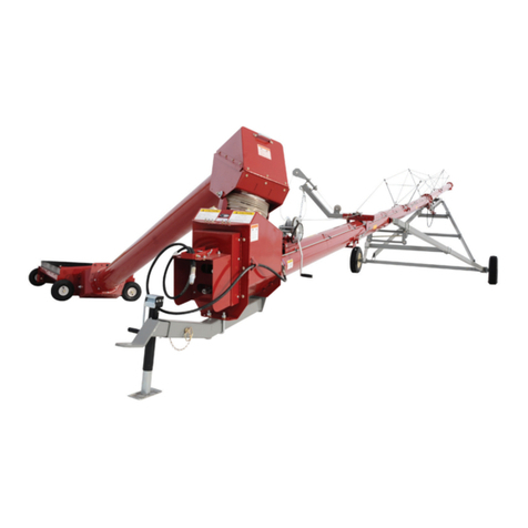
Meridian SLMD Series User manual

www.meridianmfg.com
ASSEMBLY AND
PARTS LIST MANUAL
SLMD SERIES AUGER
®
SLMD10-59 • SLMD10-66
SLMD10-72

GENERAL
A1
DECLARATION OF CONFORMITY
13000003448-10-01
We the Manufacturer:
Meridian Manufacturing Inc.
PO Box 1996 2800 Pasqua Street North
Regina, Sk,Canada
S4P 3E1
Declare the Augers listed below conform to the 2006/42/EC Machinery
Directive
SLMD10 Series
WFN 1004
The Meridian SLMD10 Series Auger and Tube Assembly
is designed for the movement of Grains and Cereals.

GENERAL
A2
TABLE OF CONTENTS
GENERAL
A1 Declaration of Conformity
A2 Table of Contents
A3 Sign Off Sheet
ASSEMBLY
B1 Set Up Procedure
B2 Tube And Truss Assembly
B4 Winch Assembly
B5 Hitch Assembly
B6 Top Lift Frame Assembly
B7 Frame Assembly
B8 Lift Arm Assembly
B9 Feed Tube Assembly
B10 Hopper Assembly
PARTS
C1 Main Frame Assembly - SLMD10-59
C3 Main Frame Assembly - SLMD10-66
C5 Main Frame Assembly - SLMD10-72
C7 A-Frame Assembly - SLMD10-59
C8 A-Frame Assembly - SLMD10-66
C9 A-Frame Assembly - SLMD10-72
C10 PTO Shaft Assembly
C11 Hopper - 74"
C13 Hopper - 60"
C15 Feed Auger Head & Tube
C17 Lift Arm
C19 Top Gear Box
C20 Bottom Gear Box
C21 Boot
C23 Tube Assembly 12-72
C25 Tube Assembly 12-79
C27 Tube Assembly 12-85
C29 Truss Assembly
C31 Fulton K1550 Brake Winch
C32 Bolt On Winch Plate
C33 Optional - Winch Hydraulic Kit
C35 Optional - Gear Reducer
C36 General Parts
INDEX
D1 Parts Index
WARRANTY
E1 Limited Warranty Statement
13000003448-02-02

DATE
EMPLOYER SIGNATURE
EMPLOYEE SIGNATURE
GENERAL
A3
MERIDIAN GRAIN EQUIPMENT SIGN
OFF SHEET
As a requirement of OSHA, it is necessary for the employer to train the employee in the safe
operation and safety procedures with this equipment. We include this sign-off sheet for your
convenience and personal record keeping.
13000004273-10-00

ASSEMBLY
B1
SET UP PROCEDURE
1. Follow and complete steps 1 through 20 on
page B2 using page B3 reference drawings
and then proceed to step 2 on this page.
2. Follow and complete steps 1 through 9 on
page B4 and then proceed to step 3 on this
page.
3. Follow and complete steps 1 through 4 on
page B5 and then proceed to step 4 on this
page.
4. Follow and complete steps 1 through 7 on
page B6 and then proceed to step 5 on this
page.
5. Follow and complete steps 1 through 6 on
page B7 and than proceed to step 6 on this
page.
6. Place assembled (FIGURE 9) under
assembled (FIGURE 1). Connect the two
assemblies with two 1" dia. x 2-1/2" bolts
and lock nuts. NOTE: Refer to (FIGURE 1)
for the top lift frame assembly mounting
location. Proceed to step 7 on this page.
7. Lift the now assembled (FIGURE 1 & 9)
together and position it over the partially
assembled (FIGURE 10). Line up bottom
of top lift frame to the top of the bottom
lift frame. Install a pivot bushing to each side.
Fasten the assemblies together at each side
with 1" dia. x 8" bolt, two plated washers and
a lock nut. Proceed to step 8 on this page.
8. Raise the auger tube assembly and then
continue with steps 7 through 10 on page B7
before proceeding with step 9 on this page.
9. Follow and complete steps 1 through 6 on
page B8, and then proceed to step 10 on
this page.
10. Hydraulic lines:
Short Line connected to upper steel hydraulic
line and hydraulic cylinder.
Connect valve to the lower steel hydraulic
line and then attach long line to valve.
Complete long line assembly with pioneer
tip.
Proceed to step 11 on this page.
11. Follow and complete steps 5 through 8 on
page B5 and then proceed to step 12 on
this page.
12. Follow and complete steps 1 through 7 on
page B9 and then proceed to step 13 on
this page.
13. Follow and complete steps 1 through 8 on
page B10 and then proceed to step 14 on
this page.
14. Check that all bolts are tightened, pins are
in place, fittings are greased and that all
safety guards and shields are installed.
Ensure proper air pressure in all tires.
13000003448-36-02

ASSEMBLY
B2
TUBE AND TRUSS ASSEMBLY
13000003448-38-02
1. Connect tube assembly A to tube assembly B as
shown in (FIGURE 01), ensure proper alignment
of flight assemblies.
2. Lift BOOT END of TUBE ASSEMBLY min. 24"
high.
3. Assemble truss risers (FIGURES 03, 04 & 05)
in the order indicated in (FIGURE 01).
4. Position one SHORT CABLE and one LONG
CABLE straight and flat on the floor to
to the left and right of the tube assembly.
5. Install SHORT CABLE spanning from (FIGURE
03 to 05). See (FIGURE 01). Fasten to
(FIGURE 05) first using 5/8" dia. bolt, flat
washer and bushing. Tighten.
6. Fasten SHORT CABLE to bottom two holes in
(FIGURE 04) using 3/8" cable clamp and nuts.
Leave loose.
7. In (FIGURE 03) partially thread one of the two nuts to
the eyebolt while attaching eyebolt to the
TUBE SADDLE.
8. Thread SHORT CABLE thru eyebolt and pull tight.
Attach two 1/4" cable clamps as shown in
(FIGURE 03).
9. Tighten partially threaded nut on eyebolt until
adequate tension is achieved on short cable.
10. Thread second nut to eyeblot and lock.
11. Repeat steps 5 to 10 to install second
SHORT CABLE.
12. Install LONG CABLE spanning from (FIGURE
03 to 06). See (FIGURE 01). Fasten to
(FIGURE 06) first using 5/8" dia. bolt, flat
washer and bushing. Tighten.
13. Fasten LONG CABLE to top two holes in
(FIGURE 03, 04 & 05) using 3/8" cable clamp
and nuts, leave loose.
14. In (FIGURE 02) partially thread one of the nuts
to the eyebolt while attaching eyebolt to
TUBE SADDLE.
15. Thread LONG CABLE through eyebolt and
pull tight, and attach two 1/4" cable clamps as
shown in (FIGURE 02).
16. Tighten partially threaded nut on eyebolt until
adequate tension is acheived on LONG CABLE.
17. Thread second nut to eyebolt and lock.
18. Repeat steps 12 to 17 to install second LONG
CABLE.
19. Lower BOOT-END to floor, and tighten all truss
riser cable clamps.
20. Refer to SET UP PROCEDURES page B1 step
2 for the next set of instructions.

DETAIL A
SCALE 1 / 20
DETAIL C
SCALE 1 / 20
DETAIL D
SCALE 1 / 50
DETAIL E
SCALE 1 / 20
DETAIL F
SCALE 1 / 20
DETAIL H
SCALE 1 / 20
DETAIL J
SCALE 1 / 20
DETAIL K
SCALE 1 / 25 DETAIL L
SCALE 1 / 25
DETAIL M
SCALE 1 / 15
DETAIL N
SCALE 1 / 15
DETAIL P
SCALE 1 / 20
DETAIL R
SCALE 1 / 20
DETAIL T
SCALE 1 / 20
A
C
D
E
F
H
J
K
L
M
N
P
R
PART NUMBERQTYDESCRIPTIONITEM
13000003507-001Tube Bottom102
13000003511-001Tube Top101
13000003070-004Cable Bracket Bushing18
13-0735-0000104Plain Washer (Inch )Type A
and B
19
13-0734-000104Regular Helical Spring Lock
Washers(Inch Series)
20
13-0702-100324
5/8-11 UNC - 2
21
13-0725-0001012Hex Nuts (Inch Series) Hex Nut3
13000003068-004
Bracket Truss Small
6
13000003069-002Small Truss Brace8
13000003079-002Main Truss34
13000003078-002Main Truss Brace35
13000003087-004Eye Bolt4
13-0702-07020217/16-14 UNC - 1.2539
13-0731-00007217/16-14 UNC Flange Nut40
13000030601-008Cable Clamp - 3/8"41
13000003085-001Long Support Cable - 220043
13000003082-001
Short Support Cable - 2200
42
13000002433-008Cable Clamp - 5/16"5
13000003080-001
Short Support Cable - 1800
42
13000003081-001Short Support Cable - 200042
13000003084-001Long Support Cable - 200043
13000003083-001Long Support Cable - 180043
T
ASSEMBLY
TUBE AND TRUSS ASSEMBLY
B3
13000003448-38-02
04 05 06 07 08
FIGURE 02 FIGURE 03
FIGURE 04
FIGURE 05
FIGURE 06
LONG CABLE SHORT CABLE
FRAME ASSEMBLY BASE PLATE TOP LIFT FRAME ASSEMBLY BASE PLATE
TUBE SADDLE
TUBE SADDLE
LONG CABLE
SHORT CABLE
LONG CABLE LONG CABLE
SHORT CABLE
LONG CABLE
SHORT CABLE
LONG CABLE
FIGURE 01
BOOT-END HEAD-END
A B

A
ASSEMBLY
B4
WINCH ASSEMBLY
13000003448-39-02
1
6
4
5
8
2
3
9
11
12
10
1. Attach item 1 to item 2 with 3/8" dia.
carriage bolts and nuts. Leave loose.
See (FIGURE 07).
2. Mount items 1and 2to item 3 using 1/2 dia.
x 5-1/2" bolt and lock nut at boot end, and 1/2"
dia. x 9" bolt and lock nut at head end.
3. Install item 4 to item 1.
4. Position item 5 on item 6 and 4.
5. Tighten chain by pulling winch assembly towards
the head-end and tighten the three carriage bolts
from step 1.
6. Install item 7 to 6.
7. Insert item 8 through items 7 & 6.
8. Install FEED TUBE ASSEMBLY HEAD END
with items 9, 10, 11 and 12 using six 7/16"
x 1-1/4" carriage bolts c/w whiz nuts.
9. Refer to SET UP PROCEDURE page B1
step 3 for next set of instructions.
FIGURE 07
FEED TUBE ASSEMBLY &
HOPPER ASSEMBLY END
(FIGURES 12 & 13)
7

ASSEMBLY
B5
HITCH ASSEMBLY
1
4
5
7
6
2
13000003448-40-03
1. Install item 1 onto 2 using 5/8" dia. u-bolt,
washers and lock nuts at HITCH END, and
three 1/2" dia. bolts and lock nuts at TUBE
END ASSEMBLY.
2. Insert item 3 into item 2 and lock in place
using item 4.
3. Insert item 5 through item 4.
4. Refer to SET UP PROCEDURE page B1
Step 4 for the next set of instructions.
5. After completion of SET-UP PROCEDURE
steps 4 through 10, continue with HITCH
ASSEMBLY steps 6 to 8.
6. Insert item 2 into item 6.
7. Insert item 7 through items 6 and 2.
8. Refer to SET UP PROCEDURE page B1
step 12 for the next set of instructions.
HITCH END
FEED TUBE ASSEMBLY &
HOPPER ASSEMBLY END
(FIGURE 12 & 13)
TUBE ASSEMBLY END
(FIGURE 01)
FIGURE 08

ASSEMBLY
B6
TOP LIFT FRAME ASSEMBLY
3
1. Lay frame out as shown in (FIGURE 09). Ensure
items 1 & 2 are on two 2x4's FLAT.
2. Fasten item 3 to item 4 using 1-1/8" dia. bolt and
lock nut.
3. Connect item 1to 4 using four 5/8" dia. x
1-1/2" UNC bolts, washers and nuts.
4. Connect item 1 to 5 using two 5/8" dia. x
1-1/2" carriage bolts, washers and nuts at the top,
and two 5/8" dia. x 1-1/2" UNC bolts, washers and
nuts at the bottom.
5. Connect item 2 to item 4 using four 5/8" dia. x
1-1/2" UNC bolts, washer and nuts.
6. Connect item 2 to 5 using two 5/8" dia. x
1-1/2" carriage bolts, washers and nuts at the top,
and two 5/8" dia. x 1-1/2" UNC bolts, washers and
nuts at the bottom.
7. Refer to SET UP PROCEDURE page B1 step 5
for the next set of instructions.
TUBE ASSEMBLY END
(FIGURE 01)
FRAME ASSEMBLY END
(FIGURE 10)
13000003448-31-01
FIGURE 09
3
2
5
RIGHT
LEFT
4

ASSEMBLY
B7
FRAME ASSEMBLY
10
2
7
8
5
11
3
6
1
9
6
1. Lay frame out as shown in (FIGURE 10), ensure
item 2 (axle) is on jack stands prior to beginning
assembly.
2. Fasten items 1 to item 2 using 5/8" dia. u-bolts.
3. Install items 3 & 4 to item 2 using 1" dia. bolts
and locking nuts.
4. Install item 5 to tabs on inside of items 3 & 4
using 5/8" dia. u-bolts.
5. Insert items 6 into 2, securing them using
items 7 & 8.
6. Refer to SET UP PROCEDURE page B1
steps 6 for the next set of instructions.
7. After completion of SET UP PROCEDURE
steps 6 through 8, proceed to step 8 on this
page.
8. Mount tires on rims and mount rims on axle
spindles.
9. Install items 9 & 10 to item 1using 5/8"
dia. u bolts.
10. Fasten item 11 to item 3 and 4 using 5/8"
dia. u-bolts.
11. Refer to SET UP PROCEDURE page B1
step 9 for next set of instructions.
13000003448-32-02
RIGHT
LEFT
TUBE ASSEMBLY END
(FIGURE 01)
TOP LIFT FRAME ASSEMBLY END
(FIGURE 09)
FIGURE 10
4

ASSEMBLY
B8
LIFT ARM ASSEMBLY
13000003448-33-02
SAFETY HOOK
CABLE
CABLE ROLLER
ASSEMBLY #3
PIPE
LIFT ARM
ASSEMBLY
CABLE ROLLER
ASSEMBLY #2
CABLE ROLLER
ASSEMBLY #1
PIN SADDLE
ASSEMBLY
1
2
3
4
5
6
7
1. Slide LIFT ARM ASSEMBLY into SADDLE
ASSEMBLY and fasten in place using items 3
and 5.
2. Install CABLE ROLLER ASSEMBLY #1 and item
7 on to pin.
3. Thread cable end from winch around CABLE
ROLLER ASSEMBLY #1 and #2 through PIPE
and around CABLE ROLLER ASSEMBLY #3.
4. Slide cable through item 2. Locate item 27"
from cable end. Bend the last 7" of cable back
onto itself and fasten using item 1. Locate Item 1
4" above item 2.
5. Slide item 6 over PIN and SADDLE ASSEMBLY
and loack in place with item 4.
6. Refer to SET-UP PROCEDURE page B1 step 10
for the next set of instructions.
FIGURE 11

ASSEMBLY
B9
FEED TUBE ASSEMBLY
1
4
3
6
5
7
13000003448-34-02
1. Assemble item 1 to item 2 with two 5/8" dia. x 1-1/2"
UNC bolt c/w lock nut.
2. Push item 3 between items 1 and 2.
3. Fasten item 3 to item 1 and 2 using two items 4.
4. Install item 5 to item 6.
5. Attach item 7 to item 2 with three 1/4" dia. x 3/4" whiz
bolts c/w whiz nuts.
6. Install UNIVERSAL JOINT to top end of GEAR BOX
SHAFT.
7. Refer to SET UP PROCEDURES page B1 Step 13
for next set of instructions
UNIVERSAL JOINT
BOOT END
(FIGURE 09)
GEAR BOX SHAFT
4
FIGURE 12
2

ASSEMBLY
B10
HOPPER ASSEMBLY
13000003448-35-02
FEED TUBE ASSEMBLY END
(FIGURE 12)
7
6
3
1
10
9
8
5
4
2
1. Fasten items 6and 7to item 1with 7
516" x 1" carriage bolts and whiz nuts.
2. Fasten item 3to item 1in desired hole
and use 34" x 11" bolt with lock nut.
3. Assemble item 4inside item 1. Fasten with
item 5 and 38" x 1" carriage bolt with whiz nut.
4. Fasten item 9 and 8to item 1with
14" x 12" whiz bolts and whiz nuts. Ensure
assembly is pulled towards FEED TUBE
ASSEMBLY END before tightening.
5. Fasten item 2to item 1with 1" x 212"
bolt, washer and lock nut.
6. Use item 10 to lock down item 9 to item 2
7. Assemble FEED TUBE ASSEMBLY
and HOPPER ASSEMBLY
(FIGURES 12 and 13) with eight 38" x 114"
whiz bolt
8. Refer to SET-UP PROCEDURE page
B1 step 14 for the next set of instructions.
FIGURE 13

PARTS
C1
MAIN FRAME - SLMD10-59
13000003448-12-01
11
10
9
12
13
14
16
17
20
21
22
19
23
25
24
32
24
8
7
1
2
3
5
18
31
24
30
24
29
24
29
24
27
24
26
24
15
6
4

Threaded Rod Assembly113000003380-001
Lock113000003382-002
Hex Cap Screw 3/4 x 4-10
413-0702-120643
Tie Rod (L.H)113000003389-004
Tie Rod213000003379-005
Tie Rod (R.H)113000003390-006
Threaded Rod Swivel Assembly113000003381-007
Hex Nut 1-8113-0725-000168
Washer Plated
213000003007-009
Spring Lock Washer 1/2213-0734-0000810
Hex Cap Screw 1/2 x 1-1/4 -13213-0702-0802011
Tie Rod Bracket U-Bolt413000003388-0012
Main Frame SLMD10-18213000002998-0013
Brace U-Bolt413000003005-0014
Cross Brace113000003001-0015
Hex Nut 5/8 -11
2813-0725-0001016
Spring Lock Washer 5/82813-0734-0001017
16" Rim213000003138-0018
Axle Support U-Bolt413000003006-0019
Frame Axle113000003002-0020
Nylon Locknut 3/4 -10213-0729-0001221
Hex Cap Screw 3/4 x 5-10213-0702-1208022
Draw Pin213000002766-0023
Hub & Spindle Complete
-
13000003150-0024
Axle Extension Assemly213000003130-0025
Tapered Roller Bearing Cone (Inner)213000001005-0026
Grease Seal
213000003133-0027
Tapered Roller Bearing Cone (Outter)213000003135-0028
Hub & Spindle
213000003131-0029
Spindle Washer213000003136-0030
Dust Cap
213000003132-0031
1/2" x 1-1/4" UNF Wheel Bolt213000003156-0032
PARTS
C2
13000003448-12-01
MAIN FRAME - SLMD10-59
REF # PART # QUANTITY DESCRIPTION
SLMD10-59

PARTS
C3
MAIN FRAME - SLMD10-66
1
2
3
5
7
8
9
10
11
12
14
13
15
16
17
18
19
20
21
22
23
25
24
26
24
27
24
28
24
29
24
30
24
31
24
32
24
13000003448-27-01
6
4

Threaded Rod Assembly113000003380-001
Lock113000003382-002
Hex Cap Screw 3/4 x 4 -10
413-0702-120643
Tie Rod (L.H)113000003389-004
Tie Rod213000003379-005
Tie Rod (R.H)113000003390-006
Threaded Rod Swivel Assembly113000003381-007
Hex Nuts 1" - 8113-0725-000168
Washer Plated
213000003007-009
Spring Lock Washer 1/2213-0734-0000810
Hex Cap Screw 1/2 x 1-1/4 -13213-0702-0802011
Tie Rod Bracket U-Bolt413000003388-0012
Main Frame 2000213000002999-0013
Brace U-Bolt413000003005-0014
Cross Brace113000003001-0015
Hex Nut 5/8 -11
2813-0725-0001016
Spring Lock Washer 5/82813-0734-0001017
16" Rim213000003138-0018
Axle Support U-Bolt413000003006-0019
Axle113000003003-0020
Nylon Locknut 3/4 -10213-0729-0001221
Hex Cap Screw 3/4 x 5-10213-0702-1208022
Draw Pin213000002766-0023
Hub & Spindle Complete
-
13000003150-0024
Axle Extension Assemly213000003130-0025
Grease Seal213000003133-0026
Tapered Roller Bearing Cone (Inner)
213000001005-0027
Hub & Spindle213000003131-0028
Tapered Roller Bearing Cone (Outter)
213000003135-0029
Spindle Washer213000003136-0030
Dust Cap
213000003132-0031
1/2" x 1-1/4" UNF Wheel Bolt213000003156-0032
REF # PART # QUANTITY DESCRIPTION
SLMD10 - 66
MAIN FRAME - SLMD10-66
PARTS
C4
13000003448-27-01

PARTS
C5
MAIN FRAME - SLMD10-72
2
1
3
5
7
8
9
10
11
12
13
14
15
16
17
18
19
20
21
22
23
26
24
27
24
28
24
29
24
30
24
31
24
32
24
25
24
13000003448-28-01
6
4

Threaded Rod Assembly113000003380-001
Lock113000003382-002
Hex Cap Screw 3/4 x 4-10
413-0702-120643
Tie Rod (L.H)113000003389-004
Tie Rod213000003379-005
Tie Rod (R.H)113000003390-006
Threaded Rod Swivel Assembly113000003381-007
Hex Nut 1" - 8113-0725-000168
Washer Plated
213000003007-009
Spring Lock Washer 1/2213-0734-0000810
Hex Cap Screw 1/2 x 1-1/4 -13213-0702-0802011
Tie Rod Bracket U-Bolt413000003388-0012
Main Frame213000003000-0013
Brace U-Bolt413000003005-0014
Cross Brace113000003001-0015
Hex Nut 5/8 -11
2813-0725-0001016
Spring Lock Washer 5/82813-0734-0001017
16" Rim213000003138-0018
Axle Support U-Bolt413000003006-0019
Axle113000003004-0020
Nylon Locknut 3/4 -10213-0729-0001221
Hex Cap Screw 3/4 x 5 -10213-0702-1208022
Draw Pin213000002766-0023
Hub & Spindle Complete
-
13000003150-0024
Axle Extension Assemly213000003130-0025
Grease Seal213000003133-0026
Tapered Roller Bearing Cone (Inner)
213000001005-0027
Hub & Spindle213000003131-0028
Tapered Roller Bearing Cone (Outter)
213000003135-0029
Spindle Washer213000003136-0030
Dust Cap
213000003132-0031
1/2" X 1-1/4" UNF Wheel Bolt213000003156-0032
REF # PART # QUANTITY DESCRIPTION
SLMD10 - 72
MAIN FRAME - SLMD10-72
PARTS
13000003448-28-01
C6
Other manuals for SLMD Series
1
This manual suits for next models
3
Table of contents
Other Meridian Tools manuals

Meridian
Meridian HARVEST H1392 User manual

Meridian
Meridian HARVEST T1342 User manual

Meridian
Meridian HARVEST T Series User manual

Meridian
Meridian HARVEST H10 Series User manual

Meridian
Meridian HVST H10 Reference manual

Meridian
Meridian HARVEST T862 User manual

Meridian
Meridian HARVEST T852 User manual

Meridian
Meridian HARVEST T832 User manual

Meridian
Meridian HARVEST H13112 User manual

Meridian
Meridian SLMD10 Guide