Merivaara Q-FLOW Instruction Manual
INSTALLATION AND MAINTENANCE
Q-FLOW
Surgical lighting system
Type: Installation and maintenance instructions First release: 28.1.2016
Document: DO1140.en Version: 2-1 18.11.2019
Merivaara Corp.
Puustellintie 2, Fl - 15150 LAHTI, FINLAND
Tel. +358 3 3394 611• Fax +358 3 3394 6144
merivaara@merivaara.com
www.merivaara.com

1 GENERAL 5
1.1 Why choose Merivaara Q-FLOW 5
1.2 Intended use 6
1.3 Essential performance 6
1.4 User identification 6
1.5 Liability 7
2 WARNING AND NOTES 8
2.1 Warning 8
2.2 Caution 11
3 INSTALLATION 12
3.1 Before installation 12
3.2 Wall installation of the system 14
3.3 Ceiling installation of the system 14
3.3.1 Raw ceiling installation 14
3.3.1.1 Fixing bracket for 1-3 PSU 16
3.3.2 Raw ceiling installation with intermediate tube set 17
3.3.3 Installing Q-Flow SOLO and Q-Flow DUO 320 18
3.3.3.1 Installing the tube to the adapting flange
(Q-Flow SOLO and Q-Flow DUO 320) 18
3.3.3.2 Q-Flow SOLO and Q-Flow DUO 320 with reinforced
ceiling flange 19
3.3.3.3 Installation of the extension arms - Q-Flow SOLO and
Q-Flow DUO 320 19
3.4 Q-Flow DUO - 3 point fixing 20
3.4.1 Installing the ceiling tube assembly 20
3.4.2 Preparing the ceiling tube 20
3.4.3 Locking of the ceiling tube with the groove pin 21
3.4.4 Secure the ceiling tube with clamping rings 21
3.4.5 Installing extension arms and protective hood 22
3.5 Power supply unit (PSU, for all models) 23
3.5.1 Replacing fuses 24
3.6 Installing the Q-Flow - 6 point fixing 25
3.6.1 Ceiling tube D110 with welded flange - Q-Flow DUO and Q-Flow TRIO 26
3.6.2 Installing extension arms to the ceiling tube D110 - Q-Flow DUO and
Q-Flow TRIO 26
3.6.3 Installing the protective hood D600 27

3.7 Installing the balance arms - Q-Flow SOLO, DUO and TRIO 28
3.7.1 Dismantling the circlip (Lock ring) from the balance arm 29
3.7.2 Balance arm adjustments (5202005) 30
3.7.2.1 Movement range of balance arm (5202005) 31
3.7.3 Low ceiling height versions of balance arms (LCH) 31
3.7.3.1 LCH (5202006) type balance arm installation with the Q-Flow 32
3.8 Adjustment of the extension arm brake force 33
3.9 Installation of the Q-Flow luminaires 33
3.10 Installation of the Q-Flow mobile 34
3.10.1 Contents of the Q-Flow mobile luminaire sub assembly 34
3.10.2 Fixing parts and required tools for the assembly 34
3.10.3 Installing the lower and upper vertical tubes 35
3.10.4 Installing the balance arm 36
3.10.5 Installing the luminaire 37
3.10.6 Preparing the Q-Flow mobile ready for use 38
3.10.7 Installation inspection 38
3.11 Q-Flow luminaire with wireless HD camera module (optional) 39
3.11.1 Installing the system containing camera and monitor 39
3.11.2 Installing the RF unit 39
3.11.3 Removing the camera 43
3.11.4 Installing the camera 45
3.11.5 Installing the wall mounted control panel (optional) 47
3.12 Definition of user interface icons 48
3.13 User interface of the Q-Flow luminaire 50
3.13.1 Starting the use 50
3.13.2 Luminaire (lamp) menu 51
3.13.2.1 Setup menu in the Lamp menu 52
3.13.2.2 Changing the language in the user interface 52
3.13.3 Camera menu 53
3.13.3.1 Setting a new white balance value 53
3.13.4Settings menu 54
3.13.4.1 Connected devices 54
3.13.4.2 Synchronizing/adding a lamp 55
3.13.4.3 Removing a lamp 57
3.13.5 Pairing the camera with the network 57
3.13.6 Starting the diagnostic test 59
3.13.7 Resetting the lamp and camera counter 60
4CLEANING 61
4.1 Covering front glass of the luminaire 61
4.2 Luminaire cleaning 61
4.3 Disinfecting 61
4.4 Sterilization 61

5 MAINTENANCE AND REPAIR 62
5.1 Preventative maintenance 62
5.2 Daily maintenance 62
5.2.1 Annual maintenance 62
5.3 Troubleshooting 62
6 TECHNICAL DATA 65
6.1 Identification plate 64
6.1.1 Labelling and symbols used on the product 66
6.1.2 Packaging labels 67
6.2 Specifications 68
6.2.1 Environmental Conditions 68
6.2.2 Classification data 68
6.2.3 Surface materials 69
6.2.4 Load data 69
6.2.5 Luminaire specifications 71
6.2.6 RF Unit specifications 74
6.2.7 Electrical specifications of HD camera module (option) 74
6.2.8 Technical specifications of HD camera 75
6.3 Dimensioning and connection diagrams 76
6.3.1 Q-Flow SOLO ceiling mounted system 77
6.3.1.1 Connection diagram - Q-Flow SOLO lighting systems 78
6.3.2 Q-Flow SOLO ceiling mounted monitor 79
6.3.3 Q-Flow DUO ceiling mounted system 80
6.3.3.1 Q-Flow DUO 360 81
6.3.3.2 Q-Flow DUO 320 ceiling mounted system 82
6.3.3.3 Q-Flow DUO - Low ceiling height system 83
6.3.3.4 Connection diagram - Q-Flow DUO and
Q-Flow TRIO lighting systems 84
6.3.4 Q-Flow TRIO ceiling mounted system 85
6.3.5 Connection diagram - Q-Flow SOLO, DUO and
TRIO ceiling mounted systems with a battery backup unit BBU (option) 86
6.3.6 Weights of the Q-Flow system components 87
7RECYCLING 88
7.1 Metals and plastics 88
8 USER GUIDANCE FOR EMC 89
8.1 Guidance and manufacturer's declaration - electromagnetic
immunity and emissions 90
NOTES
Annexes T404230, T404338,T404339, T404360, T404474, Drill guide
Copyright © 2019 Merivaara Corp. All rights reserved. 5
Read these instructions carefully to ensure safe and trouble-free operation of the Q-FlowTM luminaire. This
user manual is regarded as a part of the product. Keep the user manual near the product for further reference.
When installing additional equipment into the system, supplement these instructions with the user instructions
that came with the additional equipment.
The EN 60601-2-41 standard has been applied in the structural design of the Q-Flow system and luminaires.
The device is classified as belonging to product category I according to the directive 93/42/EEC (MDD)
including amending directive 2007/47/EC, and thus has a CE marking. This product contains a wireless radio
equipment and conforms to Radio Equipment Directive (RED) 2014/53/EU.
1.1 Why Merivaara Q-FLOW
• Compatibility towards laminar air flow
• Intuitive sterile controls for the surgeon (IntueriTM)
• Dynamic obstacle compensation (DOCTM)
• Excellent colour rendering properties
• Improved hygienic properties
• Deep stabilized column of light
• Intuitive touch controls
1. GENERAL
Health technology with a human touch
Merivaara provides a wide range of hospital-grade furniture such as operating tables,
medical lights, examination tables, trolleys and stretchers for transportation and day
surgery, as well as birthing and patient beds. Additionally, our offering
includes also revolutionary integrated OR management systems.
We believe that technology in critical operations such as
surgery has to work seamlessly together and still be easy to
use. Our operating room solutions aim to make procedures
more fluent and comfortable which, in turn, leads to
concentration, confidence and better co-operation within
the surgical team.
Established in 1901, Merivaara has more than 115 years
of experience in designing and manufacturing hospital-
grade furniture. Today our products are highly appreciated
by users in more than 120 countries thanks to their ease-of
use, durability and ergonomic design.
Merivaara’s medical products are CE-labelled an the company’s
quality management system complies with EU directives for medical device.
It is certified by DNV according to ISO 9001 and ISO 13485 standards.
The company’s environmental management system is ISO 14001:2004 certified.
Read more at www.merivaara.com.

Copyright © 2019 Merivaara Corp. All rights reserved. 6
1.2 Intended use
The Q-Flow surgical lighting system contains modern operating room luminaires which are intended to be
used in hospitals and health care centres. The luminaires are suitable for use during examinations and
surgical operations with high illumination requirements. The HD camera is intended for transferring the image
and helping the operation room personnel to follow up surgeries. The camera is not intended for diagnostic
use.
1.3 Essential performance
The essential performance of Q-Flow surgical lights and lighting system is the delivery of illumination and the
limitation of energy to the operating field. Produced total irradiance and illumination intensity of one luminaire
is <1000 W/m² / 160 000 Ec at 1m distance (lx). Complete technical details are presented in chapter
6. TECHNICAL DATA on page 65.
1.4 User identification
Merivaara's Q-Flow system and these operating instructions are intended to be used by medical personnel
and qualified technicians working in hospitals, medical surgeries, or qualified legal agencies, who have
acquired working skills by undergoing medical training and who are in possession of necessary authorisation
where required.
Mandatory personnel training for the use of Merivaara Q-Flow system must be carried out. Make sure that the
training of your personnel complies with the guidelines presented in the document no. T404474.
For your personal safety, read all safety precautions and warnings carefully in section 2. WARNINGS AND
NOTES on page 8 before using the product.
The operations which associate with adjustments necessary during the installation must be performed by a
qualified technician of the product owner operator in accordance with the safety rules and precautions
indicated in this user manual.
In case of re-adjustments for the central axis or of its components, contact technical personnel immediately.
Nursing staff or persons involved in treatment or surgical procedures are not intended to do these kind of
procedures.
Product cleaning and disinfection can only be done by duly trained personnel according to the best practices
used at the facility, strictly attended with the instructions given in this user manual.
Before use is strongly recommended to disinfect the whole system.
Disregarding the guidelines presented in this user manual can be interpreted as a user error and result in loss
of product warranty.

Copyright © 2019 Merivaara Corp. All rights reserved. 7
1.5 Liability
The contents of this user manual may be amended by Merivaara, without prior notice or any further
obligations, in order to make changes and improvements. The reproduction, including partial, or translation of
any part of this manual is forbidden without a written permission of Merivaara.
Merivaara reserves the right to change, cancel or otherwise amend the data contained in this document at any
time and for any reason without prior notice as much as Merivaara is constantly seeking new solutions which
lead to product evolution. Merivaara therefore reserves the right to make changes to the supplied product in
terms of shape, fittings, technology, and performances.
With regard to translations into languages other than English, reference is always made to the English edition
of this operator's and user manual. For the best benefit to understanding the instructions, we suggest to read
and look the corresponding pictures enclosed.
The system is delivered in pre-assembled modules, which the customer must assemble into a finished
product. Check the contents of every package for any shipping damages. The corrugated board packaging is
recyclable, whereas the plastics and styrofoam are energy waste.
On-site verification must be done by whoever is responsible for or is a holder of an office both at the public
and private establishments of the Merivaara Q-Flow system.
Merivaara does not take responsibility of consequences if the system contains other suppliers material or
components. All system parts must be tested according to EN 60601-1.
Copyright © 2019 Merivaara Corp. All rights reserved.
Copyright © 2019 Merivaara Corp. All rights reserved. 8
2.1 Warning
All warnings and items to be noted in this installation and maintenance manual are specified as follows.
Read them carefully!
WARNING! Observe to ensure user, maintenance personnel and patient safety.
CAUTION! Please observe in order to avoid causing damage to the equipment or its parts.
WARNING! Dangerous voltage! Improper installation or maintenance can cause electric shock.
NOTE! Please observe in order to improve Q-Flow properties.
SERVICE! Must be lubricated during installation and maintenance as well as when replacing parts.
WARNING!
Always switch off the luminaire and the lighting system from the power mains, and make sure the system is on
de-energized state before any maintenance or repair!
Maintenance allowed only to persons specialized and trained to Merivaara surgical lights service work.
Please read and understand the service policy and warranty terms clearly before performing any maintenance
to Merivaara surgical lights!
In order to replace the Q-Flow parts, read carefully all instructions before start any operation especially which
regards opening of the sealed cover or other inner parts of the luminaire. List of spare parts is available
separately.
Make sure the sterilizable handle is installed in place before use.
Keep the camera and the RF receiver unit at a minimum distance of twenty (20) centimetres from the living
tissue.
Do not modify the product during maintenance procedures.
2. WARNINGS AND NOTES
!
!

Copyright © 2019 Merivaara Corp. All rights reserved. 9
If more than one luminaire is focused to the same illuminance spot, total irradiance and UV irradiance can
increase over the permissible values.
Risk of ceiling tube dropping! A dropping ceiling tube can cause serious injuries. During the assembly, nobody
is allowed to stand under the central axis!
High luminous intensity, do not look directly to the light source when operating, can cause dazzling effect.
Use luminaire metal yokes only for the pre-adjustments.
Connect power supply cord to earthed power supply only!
Device can be isolated from supply mains by detaching the power supply cord!
Static charges can cause sparks harming sensitive electronic components. Ground yourself to metallic parts
before touching electronic components.
Use only spare parts acquired from Merivaara Corp. Use procedure number as a reference and check if the
part is available as a spare part from the list.
Mark the lock ring (circlip) as a single-use item and keep it in a safe place for later mounting. Follow the
instructions given in 3.7.1 Dismantling the circlip (Lock ring) from the balance arm on page 29.
If any parts are replaced, final testing must be performed before implementation.
Improper installation can cause electric shock and will void the warranty!
Copying of this document and giving it to others and the use or communication of the contents thereof are
forbidden without express authority. Offenders are liable to the payment of damages. All rights are reserved
by Merivaara Corp. in the event of the grant of a patent or the registration of a model or design.
The Q-Flow surgical lighting system must be equipped with a power supply backup system which prevents
use interruptions if failure of power supply network occurs. A power supply backup system is not included with
the system delivery.
To avoid the risk of electric shock, this equipment must only be connected to a mains supply with protective
earth.
Copyright © 2019 Merivaara Corp. All rights reserved. 10
All rated values of illumination intensity are measured as a standard 1 m distance; however, the maximum
illumination intensity is higher than rated values and it is measured from 1.3 m distance of the luminaire
surface.
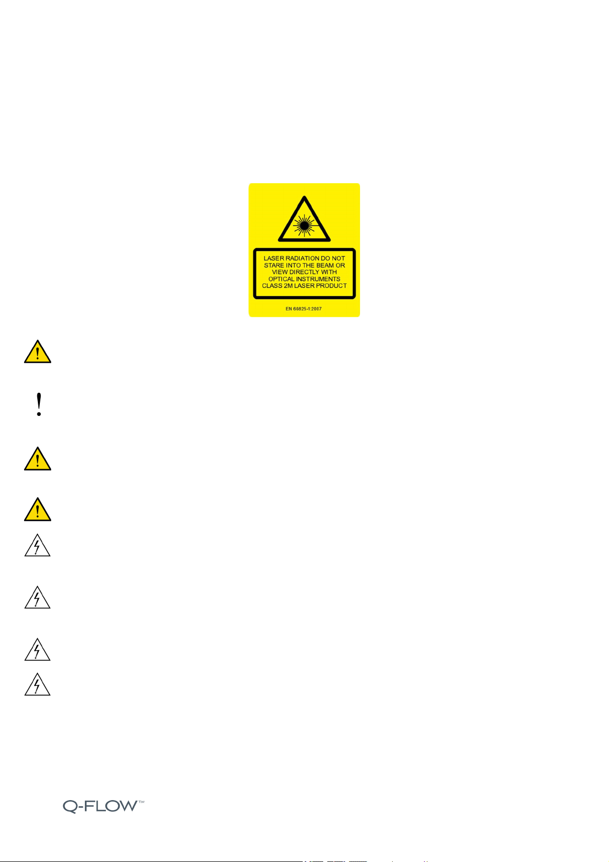
LASER RADIATION! DO NOT STARE INTO BEAM OR VIEW DIRECTLY WITH OPTICAL INSTRUMENTS,
CLASS 2M LASER PRODUCT! The laser UI feature is only on the Q-Flow i-series!
WARNING! When using the laser UI, keep the laser beam away from patient’s and employee’s eyes.
Attention, danger of injury! If necessary, use laser safety glasses!
NOTE! Activate the sterilizable focus handle
Intueri
TM
controls with laser UI from the settings menu of the
luminaire user interface.
If the luminaire hits obstacles, the sterilizable focus handle or the touch screen may get broken. Always
handle the luminaire with great care.
Faulty device must not be used, set the luminaire out of use and contact service personnel.
WARNING! During installation, ensure that no wires are pinched or otherwise damaged! A damaged wire can
cause electrical shock! The system may only be installed by trained personnel!
Faulty wiring must NOT be installed and defective products must not be used! Faulty wiring can cause electric
shock!
No user serviceable parts inside! Hazard of electric shock!
Improper installation of the system can cause electric shock and will void the warranty!
!

Copyright © 2019 Merivaara Corp. All rights reserved. 11
2.2 Caution
CAUTION!
If the system has been stored in a cold, damp place, it must be allowed to dry out in a heated room, preferably
one full day before the installation and activation. Take care of the product by following the instructions on
storage and transport presented on Chapter 6.2.1 Environmental Conditions on page 68.
If you use other supplier’s components, e.g an other power supply with Q-Flow luminaires, please read the
instructions carefully provided by the component supplier. Merivaara does not take responsibility of
consequences if the system contains other supplier’s material or components. Every system parts must be
tested according to EN 60601-1.
Improper installation of the RF receiver unit may result in disturbances in the image quality of the camera.
Other electrical equipment should not be installed adjacent to the power supply unit. If multiple power supply
units are mounted, they must not be stacked.
Ground all of the monitor bracket arm joint parts together in series and attach the grounding leads to the
sleeve of the ceiling flange.
The protective plastic covering of the luminaire must not be removed until after the final construction clean-up.
The system may only be installed by an qualified technician with the required licenses and qualifications!
Improper installation can cause electric shock and will void the warranty!
Copyright © 2019 Merivaara Corp. All rights reserved. 12
3.1 Before installation
WARNING! Remember to perform all annual maintenance measures to the system and train your service
team according to the document: T404474.
WARNING! The system may only be installed by an qualified technician with the required licenses and
qualifications! Improper installation can cause electric shock and will void the warranty!
During the concrete pouring stage, wedge anchors or threaded rods with screw anchors must be installed to
the ceiling in accordance of the instructions given in the Q-Flow Site Preparation Manual T404230. If the
system is installed into a ceiling that does not have fixings (post-installation), holes for supplied wedge
anchors has to be drilled.
Any illustrations of concrete ceiling structures and the wedge anchors in this manual are presented in order to
bring the installation of the ceiling flange and its substructures to a complete product. All technical information
concerning the wedge anchors and concrete ceiling preparation are defined in the Q-Flow Site Preparation
Manual T404230.
Definitions of the electrical requirements of the installation site for the Q-Flow system installation have been
defined also in the Q-Flow Site Preparation Manual T404230. Please complement your knowledge by reading
this Q-Flow Installation and maintenance manual thoroughly.
Professional engineer of a trusted party which is duly registered with the professional register must ensure the
structural strength of the ceiling before the installation can be done. Installation must also comply with the
local regulations, building codes and standards. Fill in the Ceiling installation sign off document no. T404360
and archive it.
Separate Q-Flow inspection forms for the installation and maintenance are presented in documents: T404338
and T404339. Make sure the measures given are followed.
WARNING! When the system is in de-energized state, make sure that the mains power cannot be switched
on accidentally during the installation.
WARNING! Before continuing the Q-Flow system installation presented in this manual, make sure the site
preparation instructions given are strictly followed.
WARNING! Because of the risk of the system or its part dropping during the installation, nobody is allowed to
stand under the ceiling tube or its substructures.
3. INSTALLATION
Copyright © 2019 Merivaara Corp. All rights reserved. 13
WARNING! If not installed properly, the ceiling flange mounting may fail and the whole Q-Flow system might
fall.
WARNING! The moment of the long extension arm places a stress on the ceiling tubes that is greater than the
weight of the luminaire, and because of this, the installation of the system must be performed carefully.
WARNING! Ensure that you have all the specified components and the supplies included with them which you
can identify with these instructions at hand. Also ensure that all components are intact and fully functional!
WARNING! Following carefully the instructions presented in this manual you can ensure that the system is
properly installed and fully operational.
WARNING! When ordering the system, height of the concrete ceiling must be indicated, because the ceiling
tube measures are defined in accordance with the height of the installation site.
This Installation and maintenance manual refers to the intermediate tube set and interface plate provided by
Merivaara Corporation. If the intermediate tube set or flange assembly provided by Merivaara cannot be
installed, re-engineered solution can be used. However, note that in this case it will be done at own risk.
Merivaara does not accept any legal responsibility for the inappropriate installation or corrupted material or
faulty structure of the ceiling.
NOTE! The Q-Flow system installation inspection must be done according to the T404338.
NOTE! Optionally, the power supply unit can be installed with an isolating transformer into the technical
space, at the maximum distance of 15 meters measured from the central axis cabling connections. This
applies also to cases in which a UPS with a back-up battery are used. General electrical requirements are
specified in the document Q-Flow Site Preparation Manual T404230.
NOTE! Merivaara recommends to use primary and secondary wiring at least 2.5 mm² cables, e.g.
MMJ 3 x 2.5 mm² or MPLM 3 x 2.5 mm².
WARNING! The electrical connections of the Q-Flow PSU are indicated in the Picture 7. Dimensions and
connections of the power supply unit (PSU) on page 23.
WARNING! Merivaara Q-Flow surgical lighting system must be installed primarily using the 6 point fixing,
Use the 3 point fixing only for a specific model with a triangular ceiling flange.
!
!
!

Copyright © 2019 Merivaara Corp. All rights reserved. 14
3.2 Wall installation of the system
When installing the Q-Flow to the wall with the wall bearing (code
5202003), follow the manufacturer’s instructions, which are
delivered with the wall bearing (refer to “Ondal Installation
instructions ACROBAT 77/2000
Wall bearing”).
WARNING! Requirements concerning the wedge anchors and the
site preparation procedure before the installation is presented in the
Q-Flow Site preparation manual, document number T404230.
3.3 Ceiling installation of the system
3.3.1 Raw ceiling installation
WARNING! Before starting the installation, the structural engineer must sign off the Q-Flow Ceiling Flange
installation Sign Off document T404360. This document must be archived by the Q-FLow light installing party.
After the installation site is prepared according to the instructions of the Q-Flow Site Preparation Manual
T404230, the system can be installed to the superstructure of the installation site by following the steps
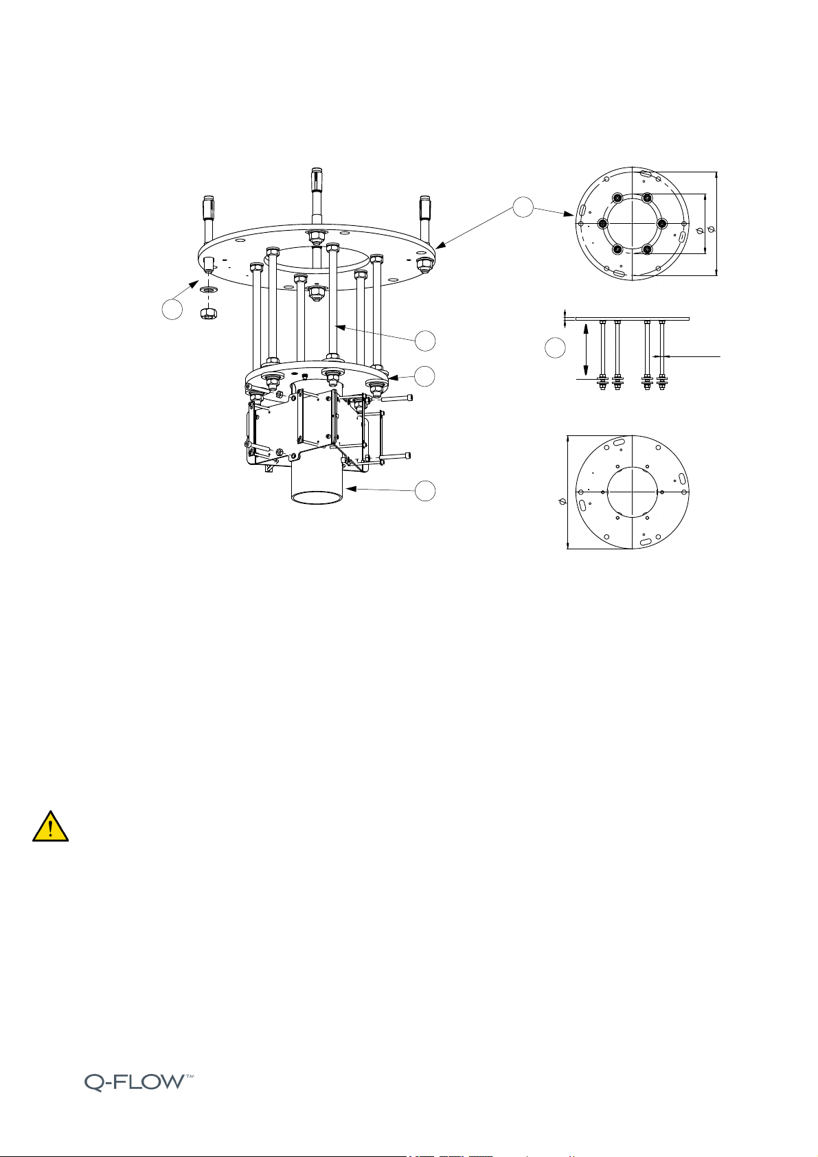
presented below (the numbers in brackets refer to the Picture 1. Installing the ceiling tube with the M16 fixing
set on page 15.) At least this fixing method must be used.
1. Prepare the interface plate and the actual ceiling flange assembly carefully before the final installation.
2. Install the ceiling tube (1) with welded flange (2) at a maximum distance of 275 mm of the surface of the
interface plate (3 and 4).
3. Cut the M16 threaded rods for even spacing and check that there is also enough space to level the ceiling
tube straight.
4. Install the M16 threaded rods (5) ,6 pcs) around the base circle of 270 mm close to actual flange (interface
plate) inner cutout. Make sure the rod ends are collinear with the ceiling flange backside edge. Tighten the
rods with M16 nuts and washers to the torque of 195 Nm.
5. Ensure that there is enough space to duct the cabling which is fed through from the ceiling tube.
Copyright © 2019 Merivaara Corp. All rights reserved. 15
Picture 1. Installing the ceiling tube with the M16 fixing set
6. Install the M16 nuts against the insulation washer set from both sides of the ceiling tube with a welded
flange to the torque of 100 Nm.
7. Fix the interface plate assembly flush to the raw ceiling with supplied M20 nuts 4 pcs and washers 4 pcs
(5). Tighten the nuts to the torque of 240 Nm. Note that there are four (4) contoured mounting holes on the
flange (interface plate) for an easy installation.
8. Use a spirit level to check the ceiling tube straightness.
WARNING! Requirements concerning the wedge anchors and the site preparation procedure before the
installation is presented in the Q-Flow Site preparation manual, document number T404230.
NOTE! The 3-point fixing is only allowed on the triangular flange of the Q-Flow DUO with the D70 ceiling
tube.
270
470
515 12
M16 x 330
max 275 mm
Nuts and washers
(HILTI HST3)
M8 screws and nuts
Fixing bracket for 1-3 PSU
Ceiling tube with a welded flange
M16 threaded rods
for fixing bracket
4xM5 screws for direct
mount of each PSU, or with
plates 2 pcs and 4xM5 screws
Interface plate
1
4
3
2
5
5
!
Copyright © 2019 Merivaara Corp. All rights reserved. 16
3.3.1.1 Fixing bracket for 1-3 PSU
An optional fixing bracket part no. A43404700 installation for the 1 to 3 pcs power supply units can be done by
stringing the bracket onto the ceiling tube.
1. Prepare the bracket and the cabling of the power supply units to be ready for the installation.
2. Take a close look to the PSU unit installation in chapter 3.5 Power supply unit (PSU, for all models) on page
23.
3. Direct mount the Q-Flow luminaire PSU with 4 pcs of M5 screws to the bracket plate.
3. There are alternative 2 pcs of securing plates for the PSU units for the use of other end devices such as
displays and monitors. In such cases, tighten the plates towards the PSU frame with M5X75 ZN SFS2219
screws.
4. Install the bracket assembly to the ceiling tube with 6 pcs M8X60 ZN SFS 2219 screws and secure it with
M8 SFS 2067 nuts (6 pcs).
WARNING! Requirements concerning the environmental conditions and general requirements of the Q-Flow
power supply unit have been specified in the Q-Flow Site Preparation Manual T404230.
WARNING! There may be limitations in this kind of PSU arrangement; if the power supply unit installation
cannot be safely covered with the protective hoods supplied, or sufficient ventilation cannot be guaranteed,
alternative options must be considered before the system installation!

Copyright © 2019 Merivaara Corp. All rights reserved. 17
3.3.2 Raw ceiling installation with intermediate tube set
The intermediate tube set is used with the intermediate ceiling structures (dropped ceiling/false ceiling) to
ensure the firm installation of any Q-Flow system.
Picture 2. Intermediate tube set for raw ceiling installation
1. After the installation site is prepared according to the instructions in the Q-Flow Site Preparation Manual
T404230, the system can be installed to the superstructure of the installation site.
2. Measure the M16 threaded rods to the correct installation length. Install the rods (6 pcs) around the
hexagonal plate base circle of 470 mm. Make sure the rod ends are collinear with the ceiling flange backside
edge. Tighten the rods with M16 nuts and washers to the torque of 195 Nm.
3. Cut the intermediate tubes 6 pcs to fit the space located between the raw ceiling and the intermediate
ceiling. Fixing disks are installed directly after of the tube ends on both sides.
4. Prepare the interface plate with a fixing set prior to complete the intermediate tube set.
5. Install the intermediate tubes with threaded rods between the plates. Metal fixing disks are intended to hold
the intermediate tubes in place to mount the interface plate towards the tubes. Tighten the M16 nuts and
washers to the torque of 195 Nm. Please take a look to the details C and D in the picture above.
470 mm
L=1100 mm
C
D
1117 mm
15 mm
1200 mm
460 mm
520 mm
C (2 : 5)
D (2 : 5)
Interface plate fixing set:
- M16 nuts 13 pcs
- M16 washers 7 pcs
- M16 spring washers 13 pcs
- Fixing discs 13 pcs
Intermediate tube set:
- (1.), Ceiling flange 1 pcs
- (2.), Metal fixing disk 12 pcs
- (3.), Intermediate tube 6 pcs
- (4.), M16 threaded rods 6 pcs
- (5.), M16 nuts 12 pcs
- (6.), M16 washers 6 pcs
- ( 7 . ) , M 1 6 s p r i n g w a s h e r s 1 2 p c s
6
2
7
5
1
6
5
3
4
2

Copyright © 2019 Merivaara Corp. All rights reserved. 18
6. Go through the steps presented in the previous section for the installation of the Interface plate and the
ceiling tube assembly. A supplied fixing set includes all parts needed for the firm installation.
7. Install the intermediate tube set with the flanges (base plate and the interface plate) flush to raw ceiling!
8. Install and set the medium duty or light duty ceiling tube after these steps by following the forthcoming
sections.
3.3.3 Installing Q-Flow SOLO and Q-Flow DUO 320
Picture 3. A ceiling tube D50 with a adapting flange assembly
WARNING! Requirements concerning the wedge anchors and the site preparation procedure before the
installation is presented in the Q-Flow Site preparation manual, document number T404230.
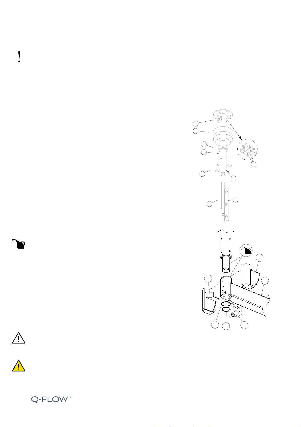
3.3.3.1 Installing the tube to the adapting flange (Q-Flow SOLO and Q-Flow DUO 320)
1. Remove the screw (1) and nut/washer (2) from the adapting flange (3).
2. Loosen the screws (4) such a way they are almost off
(6 pcs of screws).
3. Place the tube (5) inside the flange base (3) and attach it with
the fixing parts (1) and (2).
4. Tighten the screws (4) and position the tube vertically
by using a spirit level (6).
5. Connect the cables coming from the tube cutout (7) to
the connection strip (8).
6. After the ceiling tube has been installed to the adapting flange,
follow the instructions presented in the sections 3.2.1 and 3.2.2.
7. Connect the wires from the PSU to the connection strip (8), and
the yellow-green (GND/PE) wire under the earthing screw.
8. Install the protective hood (10) and secure it with screws (11) 3 pcs and collar
nuts 3 pcs.
30°
M5 / 2 pcs
ø15 / draft 5°
6 x 60°
ø20 / draft 5°
6 x 60°
ø29 draft 5°
15
15
60
60
270
270
Intermediate / Dropped ceiling
Intermediate ceiling collar
Extension arm (SOLO)
Adapting flange
1
5
2
3
6
4
7
10
11
8
Copyright © 2019 Merivaara Corp. All rights reserved. 19
NOTE! Check the length of the ceiling tube during the procedure. Recommended measure of the tube end is
about 2.25–2.35 m from the floor.
3.3.3.2 Q-Flow SOLO and Q-Flow DUO 320 with reinforced ceiling flange
This type of reinforced ceiling tube with a welded flange can be used for the light duty systems if the raw
ceiling height is over 4.4 m. It can be also replaced by using a intermediate tube set.
1. Open the screws (1) and (2) so that the screws
are almost off (6 pcs).
2. Place the ceiling tube (3) into the ceiling flange (4) and
tighten with screws (1).
3. Tighten screws (2) and position the tube vertically by using
a spirit level (5).
4. Connect the cable (6) to the connector strip (7).
5. Connect the wires of the transformer to the serial connector (7)
and the yellow-green wire under the earthing screw.
6. Install the protective hood (8) and fix it with the fixing collar (9).
3.3.3.3 Installation of the extension arms
- Q-Flow SOLO and Q-Flow DUO 320
1. Remove the lock ring (1) and the washer (2) from the ceiling tube.
•SERVICE! Grease the sliding surfaces of the ceiling tube axis
and the extension arm.
2. Lift the extension arm (3) into place and attach the washer (2) with a
clip and lock ring (1).
3. Carefully install the male half of the electric coupling (4) with the female
half located inside the ceiling arm.
4. Attach the protective end covers (5 and 6).
• Special circlip pliers needed! Pliers must be set a 8 mm strut limitation
to prevent deforming or over stretching the lock ring (circlip).
CAUTION! INSTALL THE PART 4 CAREFULLY AND ENSURE THAT THE PART 1 IS SECURELY
LOCKED INTO PLACE.
WARNING! Risk of system or its parts dropping, if the installation is made carelessly. Pay a special attention
when installing parts no. (1) and (2).
!
5
4
1
2
3
7
8
9
6
4
1
2
5
6
3
!
Copyright © 2019 Merivaara Corp. All rights reserved. 20
3.4 Q-Flow DUO - 3 point fixing
This model uses a special ceiling flange with 3 point fixing. Always install the ceiling tube D70 with a ceiling
flange assembly to the intermediate tube set by using a interface plate with a fixing set as presented in
chapter 3.3 Ceiling installation of the system on page 14, then follow the instructions presented in this chapter.
WARNING! Requirements concerning the wedge anchors and the site preparation procedure before the
installation is presented in the Q-Flow Site preparation manual, document number T404230.
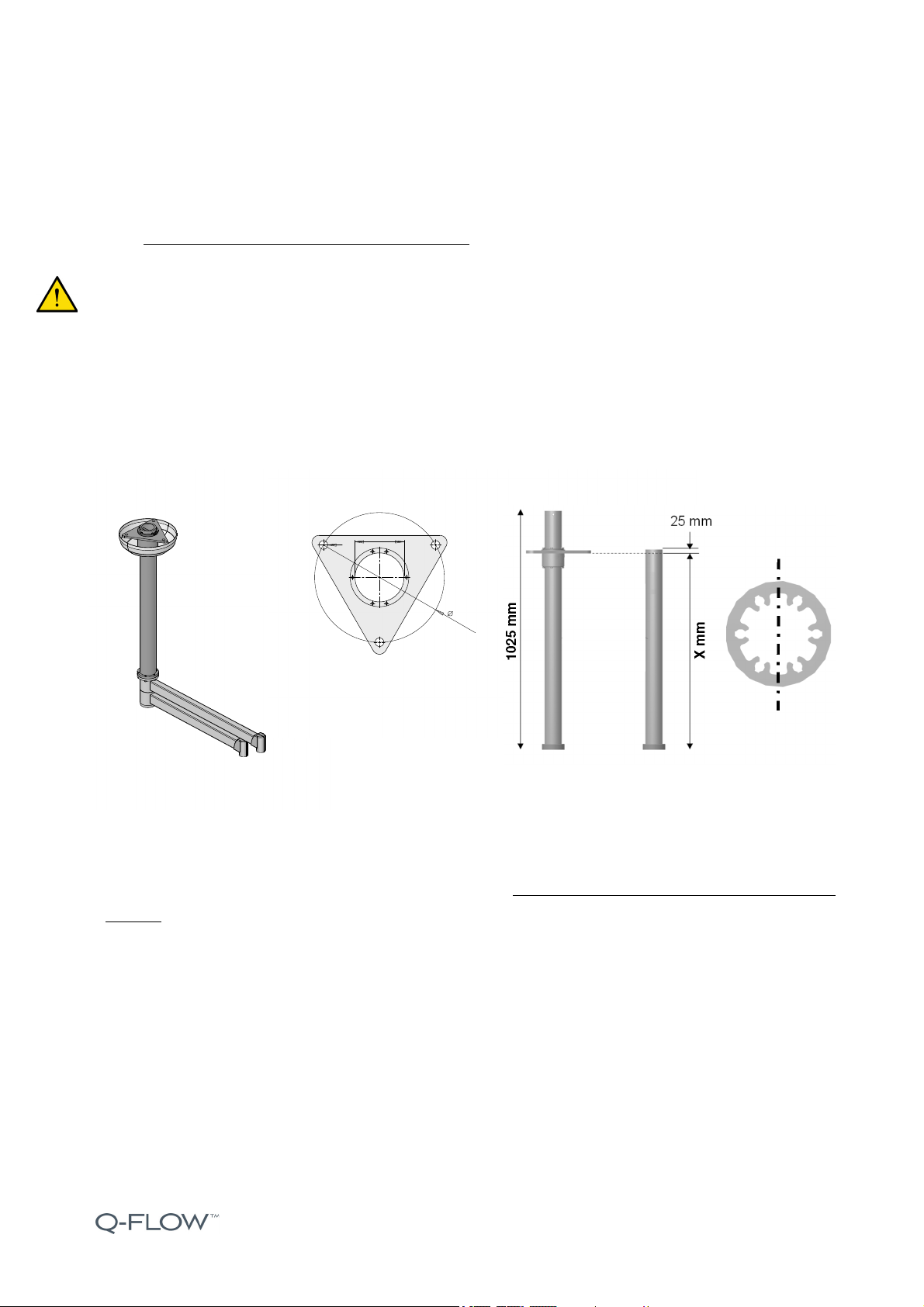
3.4.1 Installing the ceiling tube assembly
Prepare the assembly by cutting the ceiling tube to proper length matching it with the intermediate tubes and
the interface plate assembly. Follow the dimensioning of the ceiling flange as presented below.
Picture 4. Dimensioning of the ceiling flange
3.4.2 Preparing the ceiling tube
1. Place a drill hole at the calculated distance X as indicated in Picture 4. Dimensioning of the ceiling flange on
page 20. The distance is measured from the lower edge of the adapting ceiling flange with a diameter of
10.2 mm.
2. Cut the tube to a length that the distance from the centre of the drill hole to the cutting edge is 25 mm. The
maximum recommended length for the tube is 1000 mm.
3. Ensure that the hole is running through the ceiling tube cross-section in the middle (Refer to Picture 5.
Locking of the ceiling tube with the groove pin on page 21.) Use the provided template for orientation
purposes.
4. Deburr the cutting edges.
PP
Preparing ceiling tube
70 mm
20 mm
Q-Flow DUO with 3 point Triangular ceiling flange
fixing
This manual suits for next models
4
Table of contents
Other Merivaara Medical Equipment manuals


Popular Medical Equipment manuals by other brands


Getinge
Getinge Arjohuntleigh Nimbus 3 Professional Instructions for use

Mettler Electronics
Mettler Electronics Sonicator 730 Maintenance manual

Pressalit Care
Pressalit Care R1100 Mounting instruction

Denas MS
Denas MS DENAS-T operating manual

bort medical
bort medical ActiveColor quick guide

AccuVein
AccuVein AV400 user manual


