Merivaara OPTIMA MINOR Operation instructions
USE AND MAINTENANCE INSTRUCTIONS
Type: Use and maintenance instructions Completed: 4.4.2005
Document: DO1053-1-0.en Version: 1-0 11.8.2010
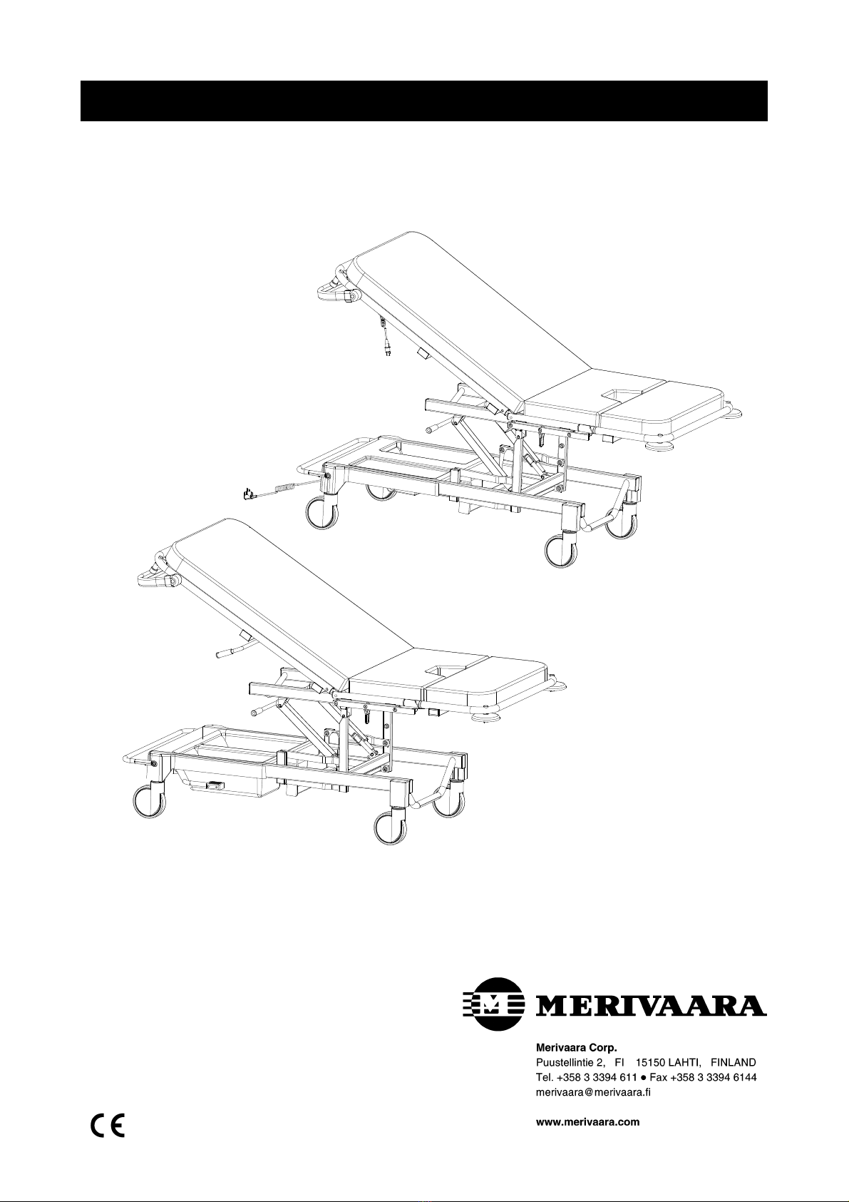
OPTIMA MINOR

Dear Merivaara product owner, The safe and fault-free use and maintenance of the equipment requires
careful adherence to these instructions. When mounting accessories to the equipment, the instructions
provided with them must be followed closely. Always keep the instructions for accessories together with this
manual.
Warnings and observations found in this instruction manual are indicated as follows:
WARNING! Please observe to ensure patient safety.
NOTE! Please observe in order to avoid causing damage to the equipment or its parts.
Lubricate during maintenance and when replacing parts.
Expertise is essential
The patient is the most important part of treatment.
This is precisely why the equipment used in
treatment must be absolutely safe and convenient
to use. As a health care professional, you deserve
the very best tools, allowing you to concentrate on
your own field of expertise. Merivaara is an expert
in providing hospital equipment.
Merivaara products have been designed to
function
efficiently and flexibly during the various stages of
treatment. They assist you in the performance of
your work, without distracting you from the task at
hand.
Our integrated equipment system includes state-
of-the-art equipment for hospital procedures and
hospital room environments as well as for nursing
homes and
home care applications.

1 TECHNICAL SPECIFICATIONS 1
1.1 Intended use 1
1.2 Type plate 1
1.2.1 Figure symbols 1
1.3 Properties and materials 2
1.3.1 Operating conditions 2
1.3.2 Classifications data 2
1.3.3 Surface materials 3
1.3.4 Adjustment ranges 3
1.3.5 Dimensions 4
2PRODUCTUSE 5
2.1 Implementation 5
2.1.1 Special instructions 5
2.2 Structure and adjustments 6
2.2.1 Brakes and castors 6
2.2.1.1 Castors with individual brakes 6
2.2.1.2 Castors with central brake system 6
2.2.2 Hydraulic/gas spring-assisted adjustments 7
2.2.2.1 Height adjustment, hydraulic 7
2.2.2.2 Back section adjustment, gas spring 7
2.2.3 Electrical adjustments 8
2.2.3.1 Hand control functions on electrically-operated bed 8
2.2.3.2 Height adjustment 8
2.2.3.3 Back section adjustment 8
3CLEANING 9
3.1 Bed, operating table and trolley 9
3.1.1 Cleaning 9
3.1.2 Disinfecting 9
3.1.3 Mattresses and pads 9
4 MAINTENANCE AND REPAIR 10
4.1 Preventative maintenance 10
4.2 Troubleshooting 11
4.3 Castors and brakes 12
4.3.1 Castors with individual brakes 12

4.3.2 Castors with central brake system 12
4.3.2.1 Brake adjustment 12
4.4 Hydraulic height adjustment 13
4.4.1 Pump removal 13
4.4.2 Pedal removal 13
4.4.3 Pump bleeding 13
4.5 Gas spring adjusters 14
4.5.1 Removal of back section gas spring 14
4.5.2 Removal of Trendelenburg adjustment gas springs 14
4.5.3 Removal of gas spring from protective sleeve 14
4.6 Control unit and motors 15
4.6.1 Removal of control unit and height adjustment motor 15
4.6.2 Removal of back section motor 16
4.7 Schematic 17
5 SPARE PARTS 18
5.1 Height-adjustable lower frame and lift levers 18
5.1.1 Height adjuster and motor 19
5.1.2 Height adjuster hydraulic pump 20
5.2 Central braking system and castors 21
5.3 Back section adjustment gas spring 22
5.4 Back section adjustment motor 23
5.5 Trendelenburg adjustment gas springs 24
6 ACCESSORIES 25
6.1 Accessories 25
6.1.1 Operating conditions 25
6.1.2 Surface materials 25
6.2 Accessory serial numbers and weights 26
6.3 Rail 27
6.4 Knee-bend support 28
6.5 Accessory rail for back section 29
7RECYCLING 30
7.1 Metals and plastics 30
7.1.1 Gas springs 30
7.1.2 Hydraulics 30
5
1.1 Intended use
Merivaara's delivery bed Optima Minor is intended for use in hospital maternity wards.
The Optima Minor delivery bed meets IEC 601-2-38, IEC 601-1-2 (EMC) and SFS-EN 60601-1 standards.
The bed complies with directive 93/42/EEC (MDD) product class I, and bears a CE marking based on this
classification.
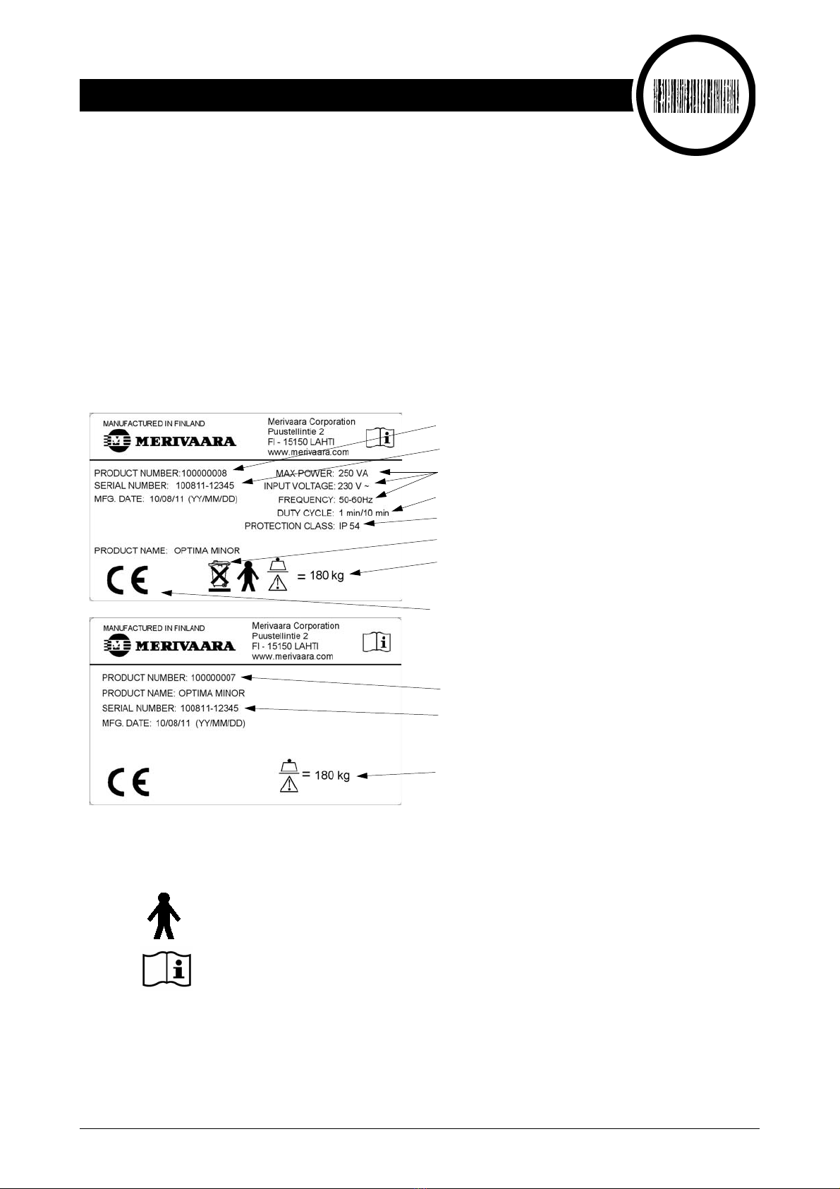
1.2 Type plate
The type plate is located underneath the back section.
Type plates, upper electrically-operated and lower hydraulic gas spring-operated bed
1.2.1 Figure symbols
Consult accompanying documents
1. TECHNICAL SPECIFICATIONS
Model number
Serial number
Safe working load (SWL)
(incl. patient, mattress and accessories)
Enclosure rating
Input voltage, frequency and input power
Periodical operation (max) 1min / 10min
Model number
Serial number
Safe working load (SWL)
(incl. patient, mattress and accessories)
Recycled separately
CE certified device
WEIGHT: 110 kg
B-type device

6
1.3 Properties and materials
1.3.1 Operating conditions
Ambient temperature +10 ... +40 °C
Ambient pressure 700 - 1060 mbar
Relative humidity 30 %- 75 %
Transport temperature - 10 ... +40 °C
Storage temperature +10 ... +40 °C
Safe working load (SWL)
(incl. patient, mattress and accessories) 180 kg
1.3.2 Classifications data
Electric shock protection Class Iequipment (insulated)
Degree of shock protection B-type device
Fluid protection water-resistant device (IP54)
Cleaning and disinfecting see section 3. page 13
Combustible anaesthetic gas protection do not use with combustible gases
Function type periodical operation
Input voltage 230 V/50 Hz
Input power max. 250 VA
Output voltage 24 V
Noise level 43±2 dB
Weight 110 kg

7
1.3.3 Surface materials
1.3.4 Adjustment ranges
Surface materials 34100 H 34100 SCK
Paint (glossy epoxy), frame parts X X
Chroming (pedal bars, adjuster levers) X X
Stainless steel (slide rail, basin) X X
ABS (casings) X X
PE (plugs) X X
POM (collision wheels) X X
TPO (Thermoplastic olefin), push bar profile X X
PU elastomer (push bar) X X
PUR (polyurethane) hand-held control cable X
PA 6 (polyamide), handles, motors X X
PA 9 (polyamide), control unit X
Lyranyl (PPE/HIPS) hand-held control X
Hygienic mattress (grey) cover 63% polyamide/37% PU X X
MAX.15
MAX. 3
MAX. 68
o1053d.pdf
Back section adjustment
Trendelenburg and anti-Trendelenburg adjustme
0 ° - 68 °
Anti-Trendelenburg MAX. 3 °
Trendelenburg MAX.15 °

8
1.3.5 Dimensions
Table 1. Dimensions
.
Optima Minor
34100 H
Optima Minor
34100 CSK
Mattress base 3-section 3-section
Bed weight 110 kg 110 kg
Length (A) 1940 mm 1940 mm
Width (B) 910 mm 910 mm
Height (C) 650 - 1010 mm 650 - 1010 mm
Castors 125 mm 125 mm
A
C
B
o1053c.pdf

9
2.1 Implementation
The bed is packaged pre-assembled. Check for damage that may have been caused during transport.
All packaging cardboard should be recycled. Wood and plastics are energy waste.
NOTE! If the bed has been stored in the cold, allow it to warm up to room temperature before
connecting power or using.
2.1.1 Special instructions
WARNING! On electrically-operated beds, ensure that the power cord does not get caught between moving
parts as they may damage or cut the cord when operated. A damaged power cord can result in
electrical shock!
The bed’s safe working load is 180 kg. Only one personmay be on the bed when adjusting.
NOTE! Do not operate the motors for more than one minute at a time (max. 1 min). Continuous
repetition of movements may overload and damage the motor.
Before moving the bed, the mattress base must be adjusted to its middle position (check visually).
When pushing the bed over a threshold or similar obstacle, always go with the head or foot of the bed first to
reduce the impact on castors or other mechanical parts.
Keep the mattress base of unattended beds in the lower position. (IEC 60601-2-38)
WARNING! When adjusting the bed, ensure that the patient’s fingers, hands or other parts of the body do
not get caught between the bed and accessories or the bed’s moving parts.
The bed can also be used with mobile personnel lifts.
2. PRODUCT USE
10
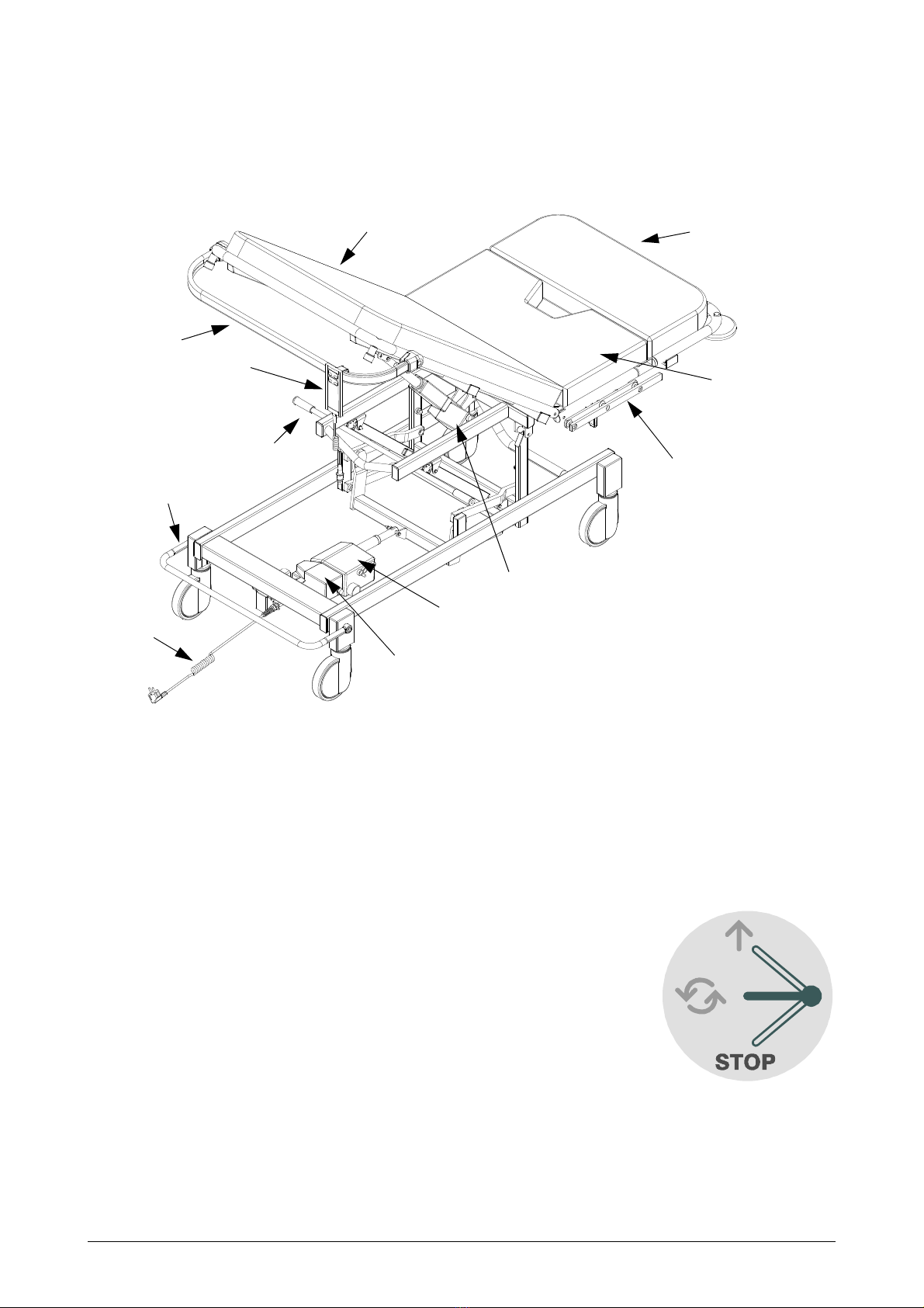
2.2 Structure and adjustments
Optima Minor – With electric adjustment (without utility basket)
2.2.1 Brakes and castors
2.2.1.1 Castors with individual brakes
The bed is locked by depressing the brake lever on all four castors. The castor brake is released by lightly
pressing the release lever until the brake lever returns to its horizontal position.
2.2.1.2 Castors with central brake system
All castors can be locked and released with a pedal, which is mounted on the lower
frame at the head end of the bed. When the pedal is up, the tracking castor will lock
in its tracking position. When the pedal is in its middle position, all the castors will
turn; when the pedal is down, all castors are locked.
o1053e.pdf
Extension/leg sectio
Push bar
Back section
Hand control
Trendelenburg adjustment handle
Power lead
Brake pedal
Accessory rail
for seat
Seat
Back section adjuster motor
Control unit
Height adjuster motor
o1011e.wmf

11
Optima Minor – With hydraulic or gas spring-assisted adjustment (without utility basket)
2.2.2 .Hydraulic/gas spring-assisted adjustments
2.2.2.1 Height adjustment, hydraulic
Mattress base height is adjusted hydraulically using the foot pedal. The mattress
base is raised by depressing the hydraulic pedal. The mattress base is lowered
when the pedal is raised.
Adjustment range 360 mm.
2.2.2.2 Back section adjustment, gas spring
Gas-assisted adjustments are made using the handle on the side of the back section.
Turn the handle with one hand while holding the back section frame with the other and
move the back section into the desired position. Release the adjuster handle when
done.
Adjustment range 0 -68°.
o1053f.pdf
Extension/leg section.
Seat
Push bar
Back section
Back section adjuster bar
Trendelenburg adjustment handle
Height adjuster pedal
Brake pedal
Accessory rail
for seat
p4-9286v.eps
p4-9284o.eps

12
2.2.3 Electrical adjustments
2.2.3.1 Hand control functions on electrically-operated bed
Adjustments are electrically operated by pressing the buttons on the
hand control. Press the button for the desired function and hold until
the table reaches the desired position or its maximum extension. If
desired, both functions can be used simultaneously. If the function
shuts down, the overload protection has been activated. If this occurs,
release all buttons and set one function at a time.
NOTE! Ensure that the hand control cord on electrically-operated
tables does not get caught between the table’s moving
parts, as this may damage or cut the cord. A damaged or
cut cord is not life threatening, because the hand control
operates on a 24V safety voltage.
NOTE! Motors on electrically-operated examination tables are not to be used continuously for more
than 1 minute.
2.2.3.2 Height adjustment
The mattress base is raised and lowered using the hand control buttons. The
adjustment range is 360 mm.
2.2.3.3 Back section adjustment
The back section angle is adjusted using the adjustment buttons on the hand control.
The adjustment range is 0-68 °.
o1009k.wmf
Back section adjustment
Height adjustment
p4-9286v.eps
p4-9284o.eps

13
3.1 Bed, operating table and trolley
NOTE! Always disconnect the equipment from the mains when beginning cleaning procedures.
3.1.1 Cleaning
• Remove all accessories and mattresses.
• Clean by wiping down with a mild alkaline detergent (pH 7-8).
3.1.2 Disinfecting:
• Remove all accessories and mattresses.
• Disinfect only when necessary.
• Wipe down the equipment with the surface disinfectant used at the facility in accordance with
manufacturer instructions, unless the surface disinfectant contains phenols and alcohol, which can
corrode plastic parts and mattresses.
NOTE! Dry the operating table carefully immediately after cleaning or disinfecting.
3.1.3 Mattresses and pads
NOTE! Read the care instructions for mattresses and pads first. The instructions can be found by,
for example, opening the zipper at the end of the mattress.
If the instructions are not listed there, refer to Section 1.
3. CLEANING
!
!
!

14
4.1 Preventative maintenance
Mark the date when the bed is taken into use next to the type plate located on the back section of the bed.
The date will provide a reference for annual servicing. Remember to mark the bed with the date when
performing the annual servicing, so that the following service date will not
require a separate reminder.
•When cleaning the bed, perform a general visual inspection, checking for any hydraulic leaks, loose
screws or parts, cracks, surface damage or missing parts.
•Perform a monthly inspection of the bed by fully extending and retracting all its adjustments. Make
the necessary repairs and adjustments.
• The following items should be serviced on an annual basis:
• check the hydraulic pump of the Trendelenburg adjuster
• ensure that the castors and brakes turn and lock smoothly and precisely
• check and lubricate joints
• Also, on hydraulic/gas spring-assisted beds:
• check condition of gas springs
• check height adjuster hydraulic pump
• On electrically-operated examination tables:
• Inspect the condition of motors, hand control, control unit and all connections.
• check all cords for fraying.
Necessary repairs must be made immediately upon detection of a fault.
Repairs to the electrical operating system and other procedures are only to be carried out by an authorised
service representative.
NOTE! The type plate information must be readily available when contacting the Service Department.
4. MAINTENANCE AND REPAIR

15
4.2 Troubleshooting
Malfunction Cause Repair
Mattress base will not rise. • Oil level low
• Air in the hydraulic system Bleed pump.
Mattress base does not lower
properly.
• Air in the hydraulic system Bleed pump.
Mattress base not maintaining
height.
•Faultyvalve
•Faultyseal
• Debris in hydraulic system
Replace pump.
Bed pulls to one side when
pushing.
• Castor sticking
• Debris in castor
Replace castor.
Clean castor.
Mattress base angle adjustments
do not remain in place.
• Gas spring is damaged
• Gas spring is installed
incorrectly
Replace gas spring.
Correct faulty installation See
section 4.5page 18.
Motor does not work. • Motor connection has come
loose
• Hand control connection has
come loose
• Power cord out of socket or
control unit
• Distribution fuse blown
• Faulty limit switch
•Faultinmotor
• Control unit current limit
exceeded due to overloading of
motor
Re-connect to control unit.
Re-connect to control unit.
Plug back into wall socket.
Contact Service.
NOTE!Replacements may only be
performed by an authorised service
representative.
Contact Service.
Contact Service.
Only one person may be on the
bed when running the motor. The
maximum allowable weight
(patient, mattress and accessories)
of 180 kg must not be exceeded.
Hand-held control unit does not
work.
• Hand control connection has
come loose
• Wire or hand-held control unit
damaged
Re-connect to control unit.
Contact Service.
The function running does not
correspond to the function button
selected.
• Motor cords in wrong order Re-connect to control unit in
numerical order.
See section 4.7page 20

16
4.3 Castors and brakes
4.3.1 Castors with individual brakes
• Remove casing (1) or utility basket.
• Remove screws (2) and washers (3).
• Remove castor (4).
Reinstall castor in reverse order.
4.3.2 Castors with central brake system
• Put brake pedal (1) into free position (pedal centred).
• Remove screw (2).
• Pull pedal bar (1) out from lever (3).
• Remove end plug (4).
• Loosen retaining screw (5) with a 3 mm Allen key.
• Pull pedal lever (3) and axle (6) out.
• Remove casing (7) or utility basket.
• Remove screws (8) and washers (9).
• Pull castor out from sleeve (10).
Reinstall castor in reverse order. Ensure that the brake pedal
and cam positions are in alignment and that the castor is facing
in the right direction.
4.3.2.1 Brake adjustment
• Put brake pedal (1) into lower position (castors locked).
• Remove screw (2).
• Pull pedal bar (1) out from lever (3).
• Loosen lever retaining screw (11) with a 3 mm Allen key.
• Pull lever (3) out from the axle (6).
• Remove casing (7) or utility basket.
• Remove screws (8) and washers (9).
• Support the bed so that the castor being
adjusted is off the floor.
• Braking power is increased by rotating the
castor clockwise (viewed from above) one half
turn at a time (in the direction of the arrow)
o1051i.pdf
1
2
3
4
o1027ac.eps
189
10
2
63
7
4
5
bed
head end
o1000i.eps

17
4.4 Hydraulic height adjustment
4.4.1 Pump removal
• Bring mattress base into its upright position.
• Remove utility basket.
• Remove circlip (1).
• Remove pivot pin (2) and plastic bushings
(3).
• Loosen nuts (4) and remove screws (5) from
both sides.
• Remove limiters (6).
• Lift the pump out from its mounting.
Reinstall pump in reverse order.
4.4.2 Pedal removal
• Remove spring locking pin (7).
• Pull pedal (8) out.
• When reattaching the pedal, insert the pin as
shown here.
4.4.3 Pump bleeding
The hydraulic pump is equipped with an automatic bleeding mechanism, which facilitates bleeding.
• Pump mattress base into its upright position.
• Give 2-4 extra pumps.
• Lower mattress base to its operating height.
o1000g.eps
2
1
8
7
5
6
4
3
8
7

18
4.5 Gas spring adjusters
4.5.1 Removal of back section gas spring
Adjust back section to its upper position and support
with, for example, a night table.
• Remove circlip (1) and tap out joint pin (2) until the
bottom end of the gas spring comes free from
bracket.
• Remove bushings (3) (2 pcs).
• Remove circlip (4).
• Using a mandrel, carefully tap joint pin (5) out until
gas spring (7) and release handle (6) come loose.
The gas spring and release handle are only being supported by the joint pin (5), so support them
when removing.
4.5.2 Removal of Trendelenburg adjustment gas
springs
• Adjust the bed into anti-Trendelenburg position
and replace one gas spring at a time so the
mattress base will not require additional support.
• Remove the circlips (1) from the bevelled end of
the pivot pin (2) and remove the pivot pins.
• Remove gas spring (3) and bushings (4).
• Removal of gas springs from protector sleeve as
in Section 4.5.3
After replacing the gas springs in the protector sleeve, remount it in reverse order and then replace the other
side. We recommend replacing both gas springs at the same time, even if one seems to be perfectly
functional.
4.5.3 Removal of gas spring from protective sleeve
• Remove the gas spring ram (1).
• Pull the gas spring (2) out of the protective tubing (3).
• Unscrew mounting bracket (4).
Count the number of turns for reassembly.
• If the gas spring requires adjustment:
• first screw the mounting piece (4) in place of the old one
• adjust making only half or single turns at a time
• if the gas spring is under load, turn counterclockwise
• if the gas spring is not released by lifting the handle, turn clockwise
5
7
6
2
3
1
4
o1051j.pdf
o1053g.pdf
1
2
3
4
2
1
o1000l.eps
1
2
3
4
5

19
4.6 Control unit and motors
4.6.1 Removal of control unit and height
adjustment motor
• Support the mattress base in its upper
position and disconnect the power
cord from the mains.
• Remove utility basket.
• Loosen the screw (1) using a TORX
wrench (T20).
• Pull the control unit (2) toward the
motor arm.
• Remove circlips (3) from both joint
pins.
• Remove joint pin (4) and plastic
bushing (5).
• Tap out joint pin (6) until motor comes
free and plastic bushing (7) can be
removed.
• Lift motor (8) out. Reinstall in reverse order.
4.6.2 Removal of back section motor
Before removing motor, support back section
carefully and disconnect power cord from
wall outlet.
• Remove circlips (1).
• Remove pivot pin (2) and plastic
bushings (3).
• Using a mandrel, tap out joint pin (4)
until bushing (6) and motor (5) come
free.
Reinstall in reverse order.
o1009j.eps
12
3
4
7
8
3
6
5
o1051k.pdf
1
3
4
5
6
1
2
20
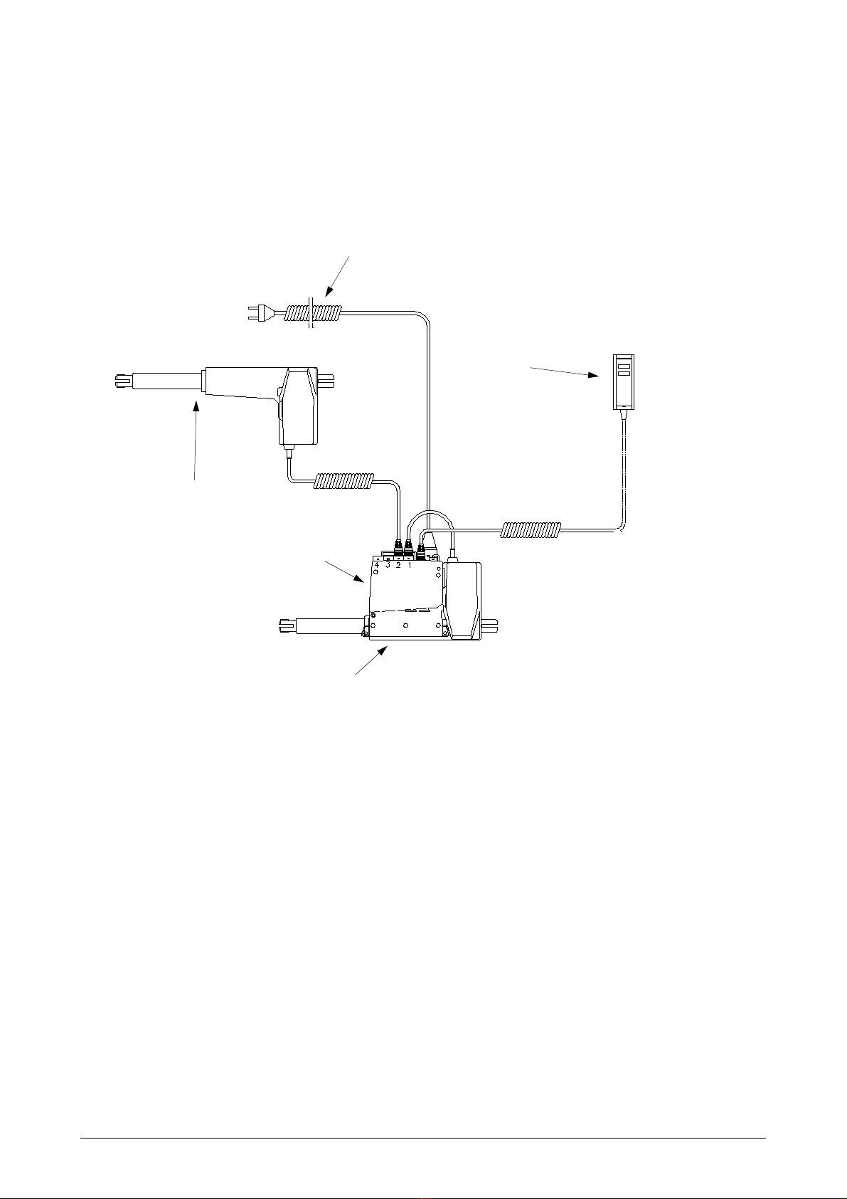
4.7 Schematic
NOTE! In order to avoid accidents, remember to always disconnect the power cord from the wall outlet
before performing any maintenance procedures!
Height adjuster motor
Hand control
Power lead
Control unit
Back section adjuster motor
Table of contents
Other Merivaara Medical Equipment manuals


Popular Medical Equipment manuals by other brands


Medrad
Medrad AngioJet Ultra Operation manual

SOMNOmedics
SOMNOmedics SOMNOwatch plus BP instruction manual

Donjoy
Donjoy dj Ortho Quadrant Application Instructions

Joycare
Joycare JC-117P manual

Weinmann
Weinmann VENTImotion Series Description of Unit and Operating Instructions for Patients

MedRx
MedRx Avant Polar HIT installation manual

Alaris Medical Systems
Alaris Medical Systems Medley 8110 Directions for use

Liko
Liko Likorall 242 Instructions for use

Stryker Medical
Stryker Medical Renaissance Series Maintenance manual

Interacoustics
Interacoustics EyeSeeCam Instructions for use

bort medical
bort medical Generation 215 900 Instructions for use

OmniPod
OmniPod DASH System quick start guide