MedRx Avant A2D+ Installation guide

D-0126017-A 1

D-0126017-A 2
0123
TÜV SÜD Product Services GmbH
Ridlerstraße 65 ◦ 80339 Munich ◦ Germany
www.medrx-int.com
1200 Starkey Rd., #105, Largo, FL 33771 U.S.A.
Toll Free: (888) 392-1234 • (727) 584-9600
Fax: (727) 584-9602 • Email: medrx@medrx-usa.com
www.medrx-usa.com
MedRx's Authorized Representative in Europe
DGS Diagnostics A/S
Audiometer Alle 1 • 5500 Middelfart • Denmark
Distributor: MedRx International
c/o MAICO Diagnostics GmbH
Sickingenstr. 70-71, 10553 Berlin, Germany
Tel.: +49 30/70 71 46-50
Fax: +49 30/70 71 46-99
Web: www.medrx-int.com

D-0126017-A 3
Contents
Getting to Know Your AVANT Audiometer........................................................4
Avant A2D+ Audiometer.....................................................................................5
Avant Stealth Audiometer..................................................................................5
Avant AIR+/Tinnometer......................................................................................5
Transducers and Accessories..............................................................................6
Loading Calibration Files.....................................................................................7
AUDIOMETER MODULE Studio Software Overview...........................................8
Audiometry.........................................................................................................9
Top Tool Bar .......................................................................................................9
Assign Transducers .......................................................................................... 10
Preparing for Testing ....................................................................................... 11
Placing the Earphones on the Patient ............................................................ 11
Sound Field Testing ......................................................................................... 13
Performing Audiometric Testing ..................................................................... 14
Pure Tone Audiometry .................................................................................... 15
High Frequency Audiometry (Optional)...........................................................17
Speech Audiometry1........................................................................................ 17
Word Recognition (WR)1..................................................................................21
QuickSIN1..........................................................................................................22
VRA MODULE1(Optional).................................................................................24
Tinnometer MODULE (Optional)......................................................................32
Hearing Loss Simulator ....................................................................................42
Master Hearing Aid ..........................................................................................42
Printing.............................................................................................................44
EMC Precautions..............................................................................................46
Safety ...............................................................................................................50
Symbols that may be used...............................................................................51
Recommended Procedures for Cleaning and Disinfection ..............................52
Technical Information ...................................................................................... 53
Limited Warranty .............................................................................................56

D-0126017-A 4
The AVANT Audiometer represents a new era of ultra-compact diagnostic
audiometry for your office. Compact yet rugged, this PC-Based system is USB
powered and supports current ANSI and IEC audiometric tests. The following
sections of this manual will familiarize you with the physical features and accessories
of the Audiometer system.
This manual assumes that the system hardware, software and drivers are installed
and working properly. Please refer to the Studio Software Installation Manual for
assistance. The Installation Manual is included in the original AVANT Audiometer
packaging in PDF format.
The scope of this manual is to get you “up and running” with your AVANT
Audiometer System. Please consult the interactive Help System within the software
for more detailed information of features and functionality. To access this tool, press
the F1 key at any time, or click the Help icon or text menu with your mouse. Access
these by clicking on the “?” icon at the top of the screen. Select an item from the list
in the Contents tab.
Getting to Know
Your AVANT Audiometer
Intended Use Statement:
The MedRx Avant series of audiometers are electronic instruments intended to
diagnose hearing loss in adults and children. Audiograms are created and used to set
the correct gain levels of the hearing aid for various frequencies. These devices
should be operated by trained professionals with education and/or training in the
field of audiometry.
Indication For Use Statement:
This device is an audiometer. For use by professionals with education and/or training
in the field of audiometry to conduct diagnostic hearing evaluations, evaluate basic
hearing function and aid in the diagnosis of otologic disorders in adults and children.

D-0126017-A 5
Avant A2D+
Audiometer
AVANT™ A2D+ is truly plug and play. The new design also
provides dual air conduction ports, allowing two separate
transducers to be plugged in simultaneously. No more
inconvenient plugging and unplugging of transducers.
Avant Stealth
Audiometer
AVANT Stealth+ has two sets of air conduction
transducer connections and two Operator Microphone
connections. High frequency transducers, such as DD450,
can be plugged into either AC 1 or AC 2 output.
Either amplified or non-amplified speakers can be
used. Amplified speakers are connected to the Free
Field (Line Out) output. Non-amplified speakers are
connected to the Free Field Loudspeaker outputs.
Avant
AIR+/Tinnometer
The MedRx Tinnometer represents a new era of ultra-
compact screening audiometry for your office.
Compact yet rugged, this PC-Based system is USB
powered and supports current ANSI and IEC
audiometric tests. This manual assumes that the
system hardware, software and drivers are installed
and working properly.

D-0126017-A 6
Transducers and Accessories
Make sure that the correct transducers are set in the software by right clicking any transducer button on the audiometry screen and left-clicking to change the
transducer. Use the accessories provided with your Audiometer. Use of unapproved accessories is not recommended.
IP30 Insert Earphones
Supra-Aural
Headphones
Talkback Microphone
Bone Conductor
Patient Response
Switch
Operator Mic &
Monitor (may vary)
USB Cable
3A Inserts (Optional)
DD450 High
Frequency
Earphones*
Stealth Power Supply
Free Field Speakers
Amplifier (Optional for
extra cost
NOTE: The Avant Audiometer supports IP30 Insert earphones, 3A Insert earphones, TDH-39,DD450, DD45 and HDA 300 extended high frequency earphones. The
standard configuration includes either IP30 Insert Earphones or DD45 or DD450 earphones.
* DD450 earphones must be ordered with the Stealth High Frequency Option Upgrade.

D-0126017-A 7
Loading Calibration Files
Each AVANT Audiometer is calibrated in compliance with the
ANSI S3.6 standard. This calibration procedure results in a series of files
that the Audiometer software reads to keep the hardware in
calibration. These files are supplied on a USB Stick.
The final step before using your AVANT Audiometer to evaluate
hearing is to load these device specific calibration files onto the
computer used to operate the Audiometer device.
1. With the MedRx USB Flash Drive connected, open the
MedRx Studio software, enter the module you will be
loading calibration files into and click:
•More Icon (three vertical dots).
•Triangle Icon.
•Load Calibration (in pop-up).
2. After a few seconds, a navigation box will appear. Navigate to the
files you would like to load.
•Click Load (choose *.set or *.cal files).
3. When the files are finished being loaded, this message will appear:
•Click OK to complete loading the calibration.
D-0126017-A 8
AUDIOMETER MODULE
Studio Software Overview
The MedRx Studio software can run stand-alone or from NOAHSystem or
the TIMSNOAH-Compatible Office System.
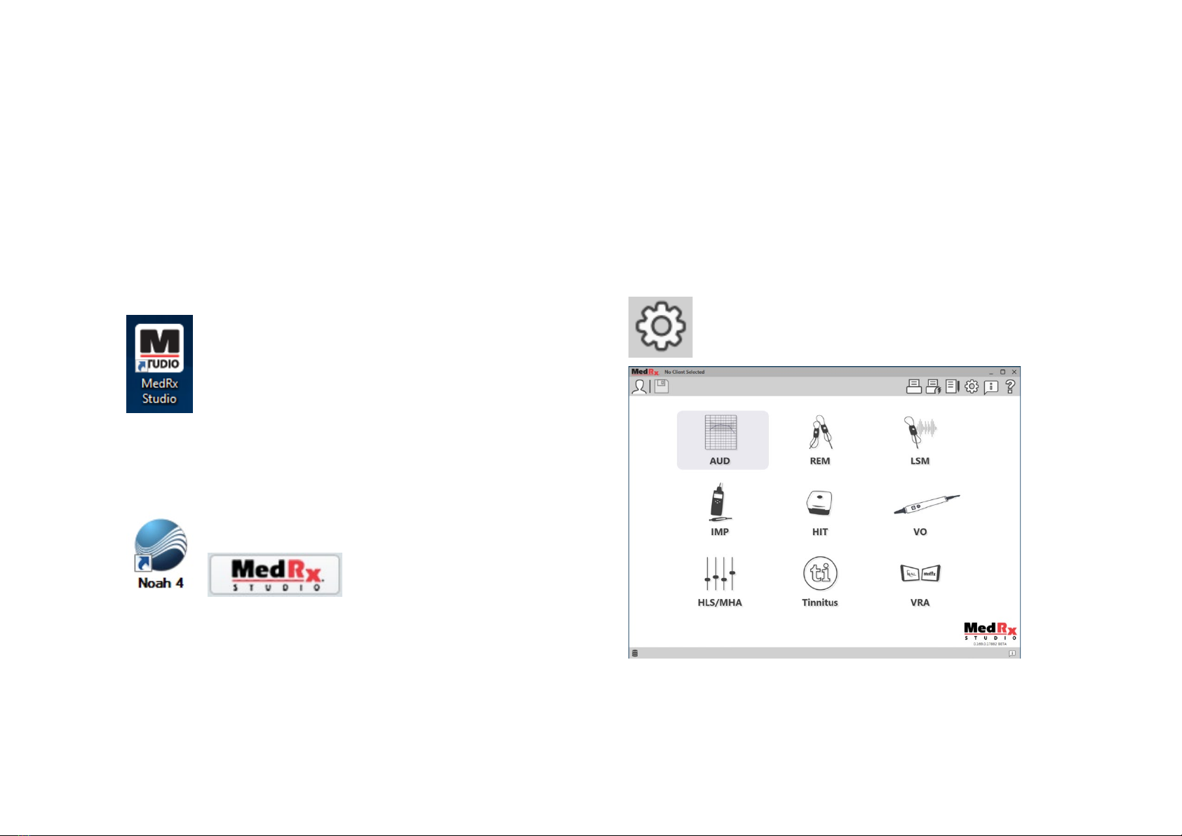
Launching the MedRx Studio Software
Stand Alone
•Double click the MedRx Studio shortcut on your Windows
Desktop.
NOAH
•Launch NOAH.
•Select a patient
•Launch MedRx Studio module following NOAH procedures.
Basic Software Options
Several options are available which allow the user to customize the MedRx
Studio Software to meet their needs.
Access these options by clicking the settings wheel in the top
right menu bar.
The MedRx Studio software main screen.
Icons are selectable depending on your equipment.
D-0126017-A 9
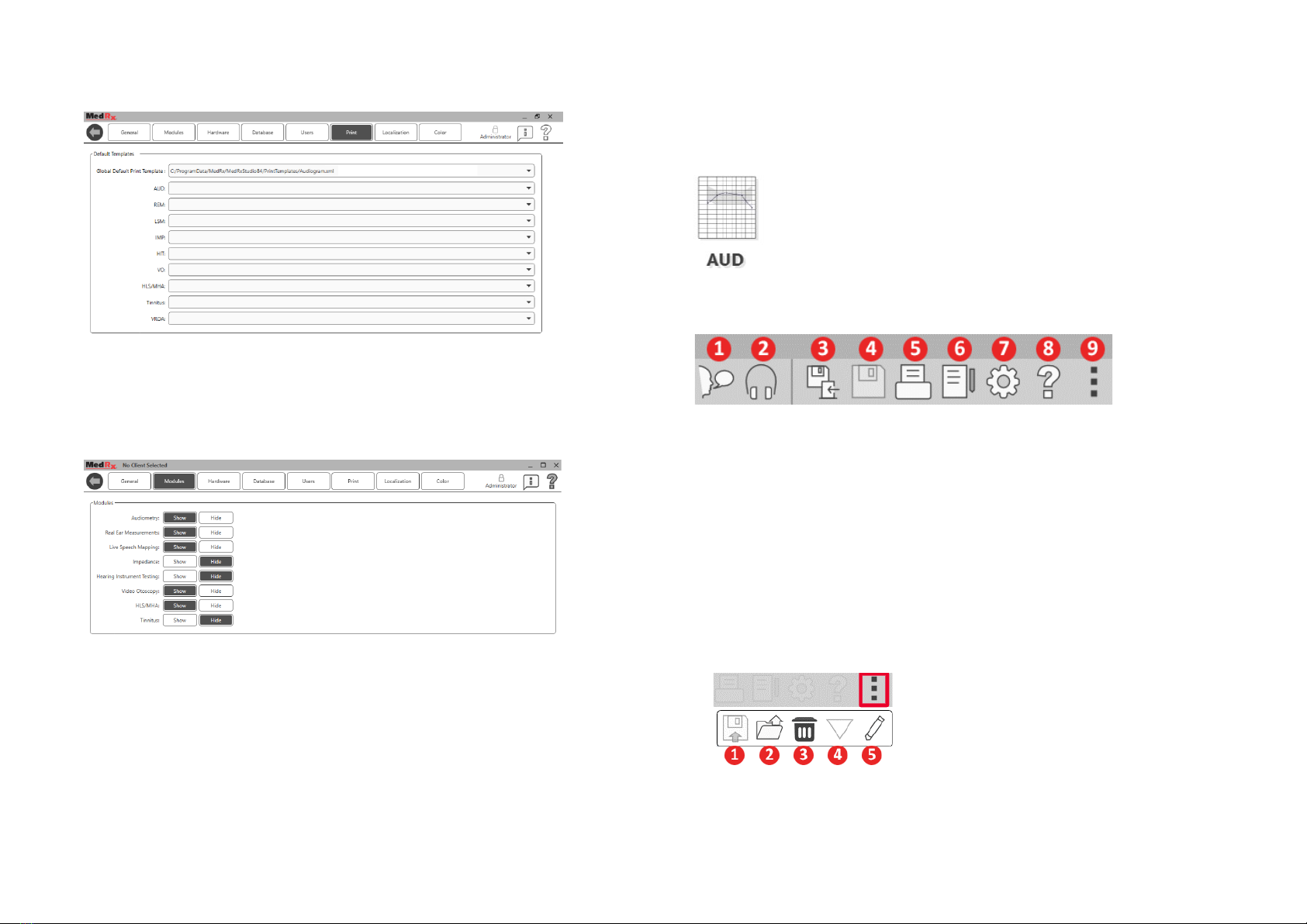
The Main Screen settings allows you to set the default modules, database,
print templates and more.
If you have more than one MedRx product you can show/hide modules in
the Main Screen settings.
NOTE:Remember, more information is always available in the Interactive
Help System by clicking the “?” Icon in the top right corner of the software
or pressing the F1 key.
Audiometry
Select AUD from the main menu.
Top Tool Bar
The Tool Bar icons have the following functions:
1. Start Talk Forward
2. Show Monitor
3. Save Session and Exit
4. Save Session
5. Print
6. Show Journal
7. Show Settings
8. Show Help
9. More Options
The More Options icons have the following functions:
1. Save the Current Session to a File
2. Open session from a file
3. Clear Data from Current Test
4. Open Calibration
5. Data Editor
D-0126017-A 10
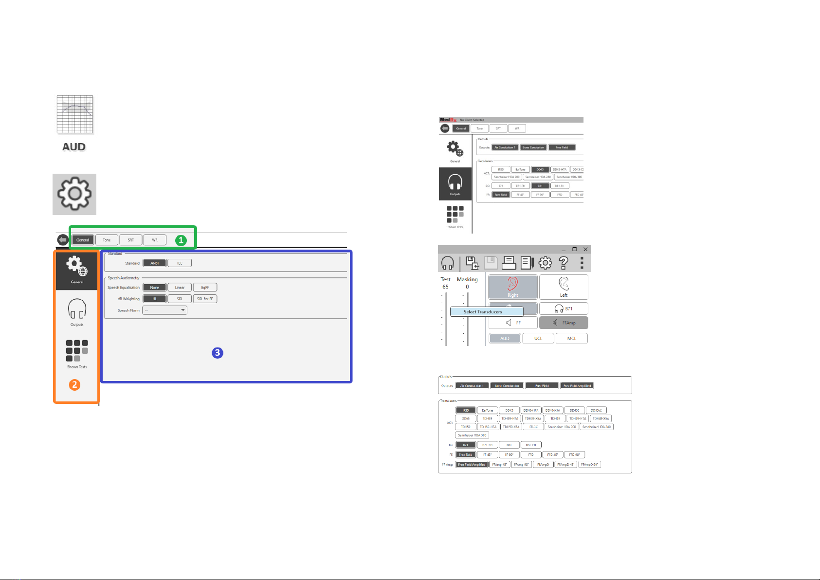
Configuring the AUD Software
It is important to note that each module will have different
settings available for customization.
Enter the module and click the settings wheel to customize.
The Audiometry module has unique settings for the module. To navigate
the settings you will:
•Select the group of settings from the header (1).
•Then choose the setting options from the left sidebar (2).
•The customization options will change based on the group and
settings chosen in the main body (3).
Assign Transducers
Option 1: On the General Options
screen click Outputs to assign specific
transducers to the audiometer
outputs.
Option 2: You can change
transducers by Right-Clicking on any
transducer icon on the Audiometry
screen.
The main body of the
settings will have options
for outputs shown and
default transducer by
output.
Select the appropriate
transducer for each output.
To add or remove outputs, click the desired outputs to enable or disable
transducer buttons on the audiometry screen.

D-0126017-A 11
Preparing for Testing
Use the accessories provided with your Avant Audiometer. Typical
acceptable transducers are shown on page 6. Operator headsets for use with
the Avant Audiometer should have 32 ohms impedance and the speaker
power should be at least 50 watts. Air conduction transducers for use with
this device should have an impedance of 10 ohms. The speaker voltage
should match the local mains voltage where the device is used.
The Operator Headset with microphone is used by the device operator to
communicate with the patient.
The patient talks to the operator using the Talk-Back microphone.
Placing the Earphones
on the Patient
Insert Earphones
IMPORTANT: The foam tips used for the insert earphones are for SINGLE
PATIENT USE ONLY. Do not attempt to wash and re-use them.
1. Place a new set of foam tips on the earphone
tubes as shown. These tips are designed for single
patient use and should not be washed and reused.
NOTE: When removing foam tips after use, be sure
the clear or black plastic tubing nipple remains
attached to the long earphone tube.
2. Carefully compress the tip between your fingers to allow it to fit into the
patient’s ear canal as shown. Do not roll the tip between your fingers.
3. Pull up and back on the patient’s pinna to straighten the ear canal.
4. Place the compressed foam tip deep within the ear canal.
5. When properly placed, the outer surface of the insert tip will be flush
with the opening of the ear canal as shown.

D-0126017-A 12
Supra-Aural Headphones
1. Place the headphones on the patient’s head so the center of the
headphone is directly over the opening of the ear canal.
2. Adjust the headband so the headphones remain in place, but be
careful not to make it so tight as to cause patient discomfort.
High Frequency Earphones - Stealth & Tinnometer
NOTE: The DD450 Earphones comes standard with the
Tinnometer and are part of an upgrade option for the
AVANT Stealth Audiometer. If you need to test
frequencies beyond 8000 Hz, you must notify MedRx.
This option carries a price differential which will be
detailed at the time of order.
1. Place the earphones on the patient’s head so the
center of the earphone is directly over the opening of the ear canal.
Adjust the headband so the earphones remain in place, but be careful not
to make it so tight as to cause patient discomfort.
Placing the Bone Conductor
1. Locate the mastoid process behind the
pinna. This is the bony shelf just behind
where the ear meets the head.
2. Carefully place the bone conductor on the
mastoid process and hold it in place.
3. Place the headband over the head to the
opposite temple.
4. Carefully and slowly loosen your grip to check if the bone vibrator
and headband will stay in place.
5. If either moves, reposition until both the headband and bone
vibrator are secure.

D-0126017-A 13
Sound Field Testing
The Sound Field speakers (Free Field) should be connected using optional or
user supplied amplifier and speakers. They should be calibrated annually as
per ISO 8253-2, located at least 1 meter from the patient ear and at the same
height.
To Install Free Field Speaker Wires:
Notice! The Red & Blue adapters are included and
must be removed to attach 18 gage (1.0mm) Free Field
speaker wires and then reinstalled.
Unplug both the Red & Blue connectors on the
Stealth audiometer.
Place a small flat head screw driver on the small orange tabs and push
down while inserting a speaker wire into the opening then remove the
screw driver. Be sure the wire is secure.
Repeat until all the speaker wires are secured then plug both connectors into
the device as indicated above.
DC Power supply must be used when using passive Free Field speakers or
performing High Frequency.
Device Maintenance
Annual re-calibration of the transducers used with the Avant Audiometer is
recommended. There are no user repairable components of this device.
Refer to the recommended procedures for cleaning and disinfection in this
manual.
Screw
Driver
Screw
Driver

D-0126017-A 14
Performing Audiometric Testing
The screen shot below shows the controls which are available from the Audiometer main window. The sections of the manual that follow explain
how to use these tools to perform hearing evaluations using your Audiometer.
1. Test Selection Tool Bar
2. Settings Selection Bar
3. Ear Selection
4. Output Selector
5. Test Type Selector
6. Tone Type Selectors
7. Test and Masking Interrupter,
Routing Selector
8. Output Level Potentiometers
9. Response Options
10. Screen Option Tabs
11. Test Results
12. Legend
13. Discard, Edit, Copy and other
options

D-0126017-A 15
Pure Tone Audiometry
Pure Tone Audiometry measures the patient’s peripheral hearing sensitivity,
or the softest levels they can hear pure tones at a variety of frequencies.
These thresholds are plotted on a standard graph called an audiogram. The
MedRx Studio software controls the hardware, stores the data (if running
within NOAH or TIMS) and prints a standard or custom audiogram report.
Pure tone Audiometry can be performed via earphones or a Bone Conductor
(Bone Conduction).
Prerequisites:
Before performing audiometry, careful inspection of the ear canal should be
performed. This is best done with Video Otoscopy. After ensuring the ear
canal is clear, place the appropriate transducer on the patient.
Pure Tone Audiometry via Earphones
IP30 Insert Earphones, Eartone 3A Inserts or Supra-Aural Headphones
1. From the main Window,
Click the AUD button.
2. By default, the Tone button will be selected once you
enter the main Audiometry Screen. Other default
settings (based on typical clinical practice and
procedures) are:
a. Right Ear
b. AC (Air Conduction)
c. Tone Stimulus
d. Continuous Tone
3. All defaults can be set in each module by clicking on the
settings wheel.
4. Instruct the patient that they will hear several very quiet (soft) tones
(beeps) and that they should signal (raise their hand, press the
patient response button, etc.) as soon as they hear it. It is helpful to
also say “even if it seems very far away”.
5. Begin at 1000 Hz in the Right ear (unless the patient reports better
hearing in the left ear).
6. Present a tone at 60 dB by pressing the space bar or clicking the
“Test” button.
7. If the patient does not hear the tone (does not signal), raise the level
5 dB using the up arrow on your keyboard and present again.
8. Repeat step 6 until the patient signals that they hear the tone.
9. When the patient signals they hear the tone, decrease the level by
10 dB and present the tone again.
10. Repeat steps 6 through 8 until the patient responds to a tone at the
same level 2 times with the level ascending.
11. Using the right arrow key, change the test frequency to 2000 Hz and
repeat steps 5 through 8 to establish the threshold at 2000 Hz.
NOTE: If the threshold at 2000 Hz is more than 20 dB different (less than or
greater than) the threshold at 1000 Hz, repeat steps 5 through 8 at 1500 Hz
(the “half octave” between 1000 Hz and 2000 Hz).
12. Repeat steps 5 through 8 for 4000 Hz, 8000 Hz, 500 Hz and 250 Hz.
13. Repeat steps 5 through 11 in the opposite ear.
NOTE: The software automatically calculates the 3-frequency Pure Tone
Average (PTA) which is displayed above and inside the legend as follows:

1Not Available in AIR+/Tinnometer D-0126017-A 16
Pure Tone Audiometry via the Bone Conductor1
1. Following the instructions on
page 12, place the Bone
Conductor on the mastoid
process behind the ear with
better air conduction
thresholds as measured
above. If the thresholds are
equal, place the Bone
Conductor on the mastoid
process behind the right ear.
2. Establish bone conduction
thresholds as described above (see page 15, steps 5-8) for 1000 Hz,
2000 Hz, 4000 Hz, 500 Hz and 250 Hz.
3. If the Bone Conduction (BC) threshold at a given frequency is less
(better) than the Air Conduction (AC) threshold by 15 dB or more,
you must confirm the threshold by performing masking.
Masking for Pure Tone Audiometry
To use the masking function on the AVANT Audiometer, follow the steps
below:
1. Click the Masking
button or press the “m” key. The button will appear grey (as
shown) indicating that the masking is on.
2. Use your mouse or hold control and use the up
and down arrow keys to adjust the Masking
Level Slider to the appropriate level based on
your preferred method of masking.
3. If you wish to maintain the
balance of signal and masking
(for example, masking always
30 dB above the signal), click
the Lock button after setting
the masking and signal levels.
4. The default for pure
tone audiometry is to
deliver narrow band masking
to the ear opposite the test ear. If you wish to use a different
stimulus, or route the masking to the same or both ears, click on the
settings wheel to the right of the Masking button.

1Not Available in AIR+/Tinnometer D-0126017-A 17
5. Use your mouse to select the
new masking type and routing
for your specific application.
6. When you are finished making
changes to the Masking, click X.
High Frequency Audiometry
(Optional)
The AVANT Stealth Audiometer is available with the option to perform
extended range high frequency pure tone audiometry. This is used clinically
to evaluate noise induced hearing loss, ototoxicity and tinnitus. High
frequency testing uses the same procedure as described on page 15 for pure
tone audiometry.
To start High Frequency audiometry, plug Stealth into DC power, select a
transducer that supports high frequencies, such as the DD450.
The High Frequency control will appear on the right panel and will allow
choosing frequency ranges to be shown on the plot. The power supply must
be connected to activate the high frequency control or when using the free
field amplifier.
NOTE: Extended High Frequency Audiometry is an upgrade option for the
AVANT Stealth Audiometer only. If the high frequency control selectors do
not appear on the right panel and if you need to test frequencies beyond
8000 Hz, you must notify MedRx. This option carries a price differential which
will be detailed at the time of order.
Speech Audiometry1
Speech audiometry evaluates how well the patient can hear and understand
speech. The typical test battery includes tests of speech threshold and tests
of speech discrimination.
The sections below detail how to perform these tests in MedRx Studio.
Speech Reception Threshold (SRT)
The Speech Reception Threshold (SRT) is defined as the lowest level at which
the patient can repeat Spondee words with 50% accuracy. Spondee words
are two syllable words with equal vocal emphasis on each syllable such as
“baseball” or “hotdog.”

D-0126017-A 18
Instruct the patient that they will hear a series of two-syllable words that will
get quieter as the test progresses. They are to repeat the words as best they
can, even if they sound very far away. If they are not sure of a word, they
should take a guess.
SRT is typically started 10-20 dB more than the patient’s Pure Tone Average,
which is displayed on the top of the screen. Set the level of the test signal to
10dB above the PTA and follow the steps as follows:
1. From the MedRx Studio main screen, click the AUD
button.
2. Click the SRT button located on the toolbar on the top
left of the screen.
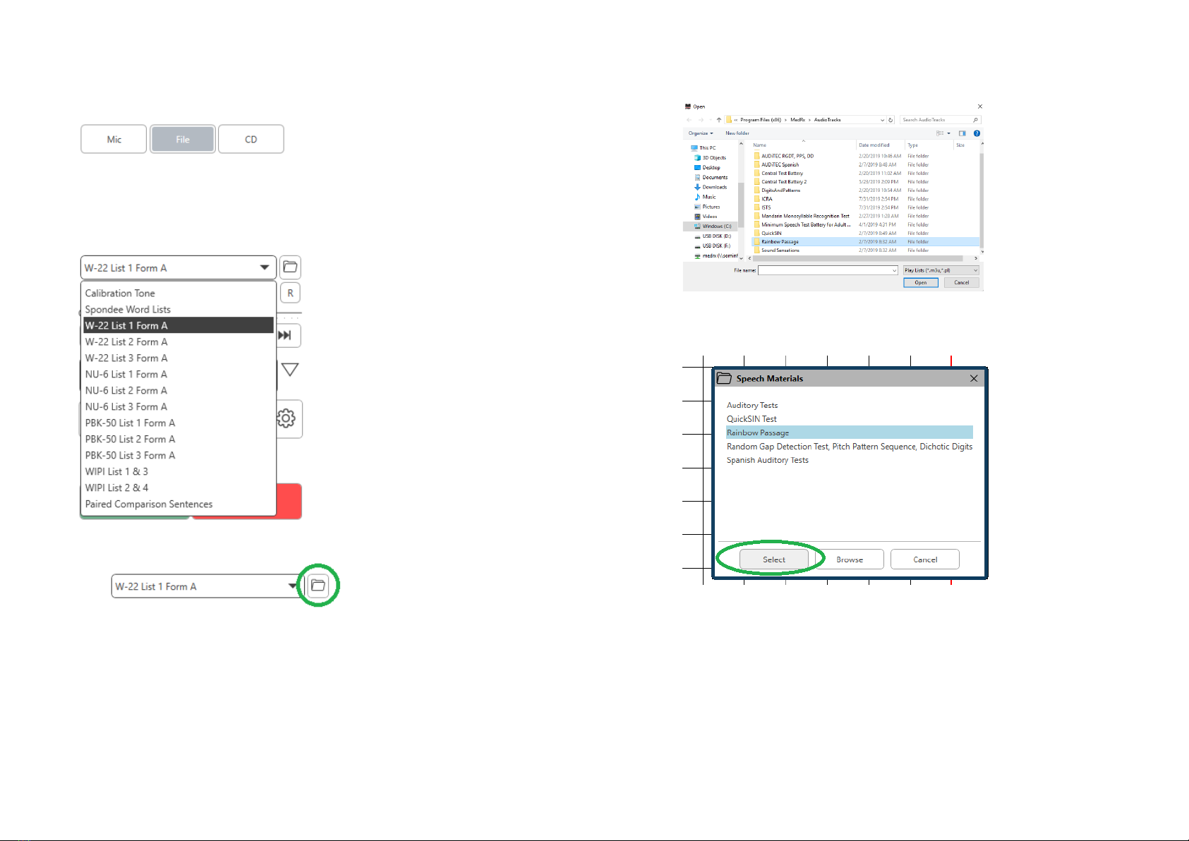
3. Click the Wtab on the bottom right.
4. Use the folder icon and drop-down list to select Spondee
Word Lists A&B or Child Spondee from the list.
5. Click the Play button or press the F9 key to present a
word. The word will play through the chosen transducer
as well as display on the screen.
6. If the patient correctly repeats the word, click the Correct button or
press F7.
7. If the patient incorrectly repeats the word, click the Incorrect button
or press F8.
NOTE: F7 and F8 auto advance the playlist to the next word but will not play
the next word. F9 plays the highlighted word. F10 advances to the next word
and plays it.
The score is calculated and displayed automatically.
If the patient exceeds a 50% score at a given presentation level, stop the test
and decrease the level by 10 dB and repeat the steps above.
If the patient fails to achieve a 50% score after 6 words at a given level, stop
the test, raise the level 5 dB and repeat the steps above.
When the patient scores 50% at a given level, the test is complete. The
software automatically plots the score on the SRT graph.
Speech MCL & Speech UCL
The patient’s most Comfortable Level and Uncomfortable Level for speech
can be obtained while you are in Word Recognition (WR).
1. From the MedRx Studio main screen, Click the
AUD button.
2. Click the WR button located on the toolbar on the top
of the screen.
3. Click UCL or MCL.
D-0126017-A 19
4. Choose an input option.
5. If you selected File or CD*, select
the track you would like to play for
the test in the media player at the
bottom of the screen.
When you have selected your track
in the media player, click play on
media player or hit the spacebar to
start.
Adjust levels up or down with
keyboard arrows or by clicking
below the dB level at the bottom of
the test slider or masking slider.
NOTE: *CD function will only be
displayed if you have a disc drive
6. To Input & Calibrate the Rainbow Passage in WR for MCL:
a. Press the small file folder on the top right of media player.
Then select “Browse” in the speech material.
b. Select Rainbow Passage by double clicking twice.
c. The Rainbow Passage is now part of the MedRx Studio
Audio Files for future use.

D-0126017-A 20
d. Use the drop down in the media player and select track 10 –
Calibration (1000Hz).
e. Click play or start signal.
f. Then click the calibration arrow next to the UV meter.
g. On the VU meter pop-up, press the slider calibration icon just
below the VU meter.
h. Adjust with mouse or arrow keys so that the blue bar stops
over the black arrow and there is no red.
i. Click on the channel icon just below and to the right of the VU to
switch channels.
j. Repeat steps d - f for the remaining channel.
Note: This calibration also needs to be done with any custom word
list.
7. When using the Mic or live voice option make sure you press the
Test or space bar to begin.
8. When using the Mic option adjust your input using the slider so
that it is peaking at the black triangle under the VU meter.
The VU meter is just below the Test button in MedRx Studio and
will become active once you press Test.
Other manuals for Avant A2D+
5
This manual suits for next models
2
Table of contents
Other MedRx Medical Equipment manuals

MedRx
MedRx Avant REM Speech Installation guide

MedRx
MedRx Avant Polar HIT User manual

MedRx
MedRx LSM User manual

MedRx
MedRx AVANT REM Speech+ User manual

MedRx
MedRx AVANT ARC User manual

MedRx
MedRx Avant A2D+ User manual

MedRx
MedRx Avant A2D+ User manual

MedRx
MedRx Avant User manual

MedRx
MedRx Video Otoscope User guide

MedRx
MedRx Avant A2D+ Installation guide


