1.
INSTALLATION INSTRUCTIONS
HVIOM-3
HIDEAVECTOR3
315 OSER AVENUE, HAUPPAUGE, NEW YORK 11788
GENERAL DESCRIPTION
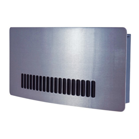
HIDEAVECTOR3 heaters are for use with forced hot water residential heating systems and consist of a serpentine
copper tube, aluminum finned heating element, with an electric motor and blower of unique cross flow design. Their
purpose is to deliver a comfortable stream of warmed air, at or near floor level, and their construction is extremely
compact so minimum space is required for installation. This unit is primarily used in horizonal floor installation, for
example: under a kitchen counter cabinet, or bathroom sink enclosure. Although it is also available for verticle mounting,
fully recessed in the wall studs, with the air discharged upward through a flush mounted, louvered front panel. All
types have heating elements with 1/2" nominal (5/8 O.D.) copper tube connections, and 115V. electric blower motor,
interwired with a 120° F (49° C) reverse acting aquastat that prevents operation until hot water is circulating. These units
are NOT intended to be used on one or two pipe steam systems. See bottom of page 7. For gravity fed systems, it is
recommended that a separate circulator pump be installed for the kick space heater.
INSTALLING HIDEAVECTOR (FLOOR MOUNT)
1. Select a location under the bottom shelf of a cabinet that meets the minimum dimensions shown in Fig. 1.
2. CUT AN ACCESS PANEL THROUGH THE BOTTOM OF THE CABINET AT THIS LOCATION, LARGE ENOUGH
FOR INSTALLATION AND SERVICE. IT IS RECOMMENDED THAT THIS ACCESS PANEL BE CONSTRUCTED SO
ANNUAL CLEANING OF THE BLOWER FAN AND COIL FINS CAN BE EASILY ACCESSIBLE.
3. At this location, center and cut an opening in the toe-space riser 4'' high x 11'' long (HAV-48-3) (See figure 1)
or 4'' high x 18'' long (HAV-88-3) (See figure 2).
4. Set the HIDEAVECTOR3 in the space at finished floor level and check piping and wiring locations. The air outlet
should be facing but not extending beyond the toe-space riser at the opening. The air outlet should also be located at
the bottom portion of the 4'' toe-space riser (See figure 1) at finished floor level. Make sure the switch is accessible
through the grille opening. The front of the unit should fit flush to the inside of the toe space riser.
6. If using the "Easy Connect" Flexible Hose Connection Kit, see those installation instructions.
7. Next, prepare the heating element for pipe connections (this procedure will also pertain to floor and wall models).
Remove the screws from the electric conn. box. Unsnap (pull) the thermostat clamp from the return copper U-bend.
Holding down the top cover, remove the 4 element cover screws. Carefully remove this top cover noting the position of
the element and the neoprene side pad. Lift out the element for soldering and fittings. Both ends are sized to accept
1/2'' solder fittings. (Note required fittings for one pipe and two pipe systems on page 6).
8. Replace the heating element in the bottom cover in the proper position. Place the neoprene side pad in position and
replace the top cover using the 4 screws. Tighten enough to keep the element in place between the covers. DO NOT
OVER-TIGHTEN!
9. Place the HIDEAVECTOR3 under the cabinet and connect the piping and wiring. Make sure unit & outlet are free
of any dirt or debris prior to start up. Turn on the system, purge of air, check blower operation and check for any
possible leaks in the piping (run for 2 hrs. minimum). It should then be screwed to the floor through the four resilient
mounting feet (2-inside electrical box and 2 external). Do not over-tighten screws. Secure top of electrical box.
ATTENTION:READTHESE INSTRUCTIONS CAREFULLY BEFORE ATTEMPTINGTO INSTALL,OPERATE,OR SERVICE
THE EMBASSY HIDEAVECTOR3 HEATERS! RETAIN THESE INSTRUCTIONS FOR FUTURE REFERENCE.
INSPECT THE SHIPMENT IMMEDIATELY WHEN RECEIVED TO DETERMINE IF ANY DAMAGE HAS
OCCURRED DURING SHIPMENT.
PRIOR TO INSTALLATION, CHECK FOR ANY VISIBLE DAMAGE. MAKE CERTAIN THAT ANY
LOOSE PARTICLES ARE REMOVED (ESPECIALLY IN THE BLOWER ASSEMBLY AREA).


