Met One BAM 1020 Installation manual

Met One Instruments, Inc.
1600 NW Washington Blvd.
Grants Pass, OR 97526
Telephone: (541) 471-7111
Facsimile: (541) 471-7116
www.metone.com
BAM 1020 Particulate Monitor Operation Manual - © Copyright 2016 Met One Instruments, Inc. All Rights Reserved
worldwide. No part of this publication may be reproduced, transmitted, transcribed, stored in a retrieval system, or translated
into any other language in any form without the express written permission of Met One Instruments, Inc.
BAM 1020
PARTICULATE MONITOR
OPERATION MANUAL
BAM 1020-9800 REV W

BAM 1020-9800 Manual Rev W.docx Page 2
Table of Contents
1INTRODUCTION 4
1.1 About This Manual..................................................................................................... 4
1.2 Technical Service....................................................................................................... 4
1.3 BAM: Beta Attenuation Monitor.................................................................................. 5
1.4 Beta Radiation Safety Statement............................................................................... 5
1.5 BAM 1020 US-EPA Configurations............................................................................ 6
1.6 BAM 1020 Other Configurations ................................................................................ 6
1.7 BAM 1020 Specifications ........................................................................................... 7
2SITE SELECTION AND INSTALLATION 8
2.1 Unpacking, Inspection, and Evaluation Testing ......................................................... 8
2.2 Enclosure Selection and Temperature Control........................................................... 8
2.3 Site Selection and Inlet Positioning Criteria ............................................................... 9
2.4 Mounting Options in a Walk-In Shelter....................................................................... 9
2.5 BAM 1020 Installation Instructions........................................................................... 10
2.6 BAM 1020 Power and Electrical Service.................................................................. 19
3INITIAL SETUP OF YOUR BAM 1020 20
3.1 Power Up ................................................................................................................. 20
3.2 Warm-up Period....................................................................................................... 20
3.3 The Main Menu and Using the Keypad and Display ................................................ 20
3.4 Filter Tape Loading.................................................................................................. 22
3.5 Self-Test................................................................................................................... 23
3.6 Initial SETUP Settings Considerations..................................................................... 24
3.7 Initial Leak Check and Flow Check.......................................................................... 25
3.8 Starting a Measurement Cycle................................................................................. 25
3.9 Accessing the Flow Statistics Screen....................................................................... 25
3.10 The OPERATE Menus............................................................................................. 26
3.11 The NORMAL Operation Screen.............................................................................. 26
3.12 The INSTANTANEOUS and AVERAGE Operation Screens ................................... 27
4THE MEASUREMENT CYCLE 28
4.1 The One-Hour Cycle Timeline.................................................................................. 28
4.2 Automatic Span Checks During The Cycle .............................................................. 29
4.3 Filter Tape Use......................................................................................................... 30
5FLOW SYSTEM and FLOW CALIBRATIONS 31
5.1 Flow System Diagram.............................................................................................. 31
5.2 Flow Control and Flow Reporting Types –Standard or Actual Flow........................ 31
5.3 Total Flow (QTOT) and Flow Rate (LPM) Conversions.............................................. 32
5.4 About Leak Checks, Nozzle Cleaning, and Flow Checks......................................... 32
5.5 Leak Check Procedure............................................................................................. 33
5.6 Nozzle and Vane Cleaning Procedure..................................................................... 34
5.7 Field Calibration of the Flow System –Actual Flow Mode ....................................... 36
5.8 Field Calibration of the Flow System –Standard Flow Mode................................... 38
6SETUP MENU DESCRIPTIONS 39
6.1 CLOCK Setup Screen.............................................................................................. 40
6.2 SAMPLE Setup Screen –Range, Sample, and Timing Settings.............................. 40
6.3 CALIBRATE Setup Screen –Flow and Calibration Settings..................................... 42
6.4 EXTRA1 Setup Screen ............................................................................................ 44
6.5 ERRORS Setup Screen for the Analog Output........................................................ 44

BAM 1020-9800 Manual Rev W.docx Page 3
6.6 PASSWORD Setup Screen...................................................................................... 46
6.7 INTERFACE Setup Screen...................................................................................... 47
6.8 SENSOR Setup Screen for External Met Sensors................................................... 47
6.9 HEATER Setup Screen –RH Control Settings ........................................................ 49
6.10 QUERY Setup Screen –Custom Data Array Setup................................................. 50
6.11 REPORTS Setup Screen –Daily Data and Dynamic Ranges.................................. 52
6.12 HJ 653 Setup Screen –Chinese Data Formatting ................................................... 53
7MAINTENANCE, DIAGNOSTICS and TROUBLESHOOTING 54
7.1 Met One Recommended Periodic Maintenance Table............................................. 54
7.2 BAM 1020 Error and Alarm Descriptions ................................................................. 55
7.3 Comparison of BAM 1020 Data to Integrated Filter Sampler Data........................... 59
7.4 Power Up Problems and Electrical Safety Considerations....................................... 60
7.5 Basic Problem and Cause/Solution Table................................................................ 61
7.6 Nozzle Component Service and O-ring Replacement.............................................. 64
7.7 Performing the 72-Hour Zero Filter Background Test .............................................. 65
7.8 The TEST Menu System –Overview....................................................................... 67
7.9 COUNT Test Menu –Beta Detector Count Tests .................................................... 67
7.10 PUMP Test Menu –Manual Pump and Nozzle Tests .............................................. 68
7.11 TAPE Test Menu –Manual Filter Forward/Backward Tests..................................... 68
7.12 DAC Test Menu –Analog Output Test..................................................................... 68
7.13 CALIBRATE Test Menu –Span Membrane Mass Tests.......................................... 69
7.14 INTERFACE Test Menu –Relay I/O Channel Tests................................................ 70
7.15 FLOW Test Menu..................................................................................................... 70
7.16 ALIGN Test Menu –Tape Transport Motor and Photosensor Tests........................ 70
7.17 HEATER Test Menu................................................................................................. 71
7.18 FILTER-T Test Menu –Filter Temperature Sensor Tests........................................ 71
7.19 RH Test Menu –Filter Humidity Sensor Test and Calibration.................................. 72
8EXTERNAL DATA LOGGER INTERFACE SYSTEM 74
8.1 Analog Concentration Output Signal........................................................................ 74
8.2 Early Cycle Mode Option For Analog Data Collection.............................................. 75
8.3 Telemetry and Error Relays ..................................................................................... 76
8.4 Interfacing a Digital Data logger with the BAM 1020................................................ 79
9DIGITAL COMMUNICATIONS AND DATA RETRIEVAL 80
9.1 Direct Serial Port Connections and Settings ............................................................ 80
9.2 Using Met One Comet Communications Software................................................... 81
9.3 Downloading Data Using Simple Terminal Programs .............................................. 82
9.4 System Menu and File Descriptions Using a Terminal Program.............................. 83
9.5 Printer Output Port Functions................................................................................... 89
9.6 Modem Option.......................................................................................................... 90
9.7 BAM 1020 Firmware Upgrades................................................................................ 90
9.8 Resetting the Data Pointer for New Data Collection................................................. 93
9.9 Data Collection Using the Query Output or Bayern-Hessen Protocol ...................... 93
10 ACCESSORIES and PARTS 96
10.1 Consumables, Replacement Parts, and Accessories............................................... 96
10.2 BX-500 Series Meteorological Sensor Configurations ........................................... 101
11 THEORY OF OPERATION 103
11.1 Converting Data Between EPA Standard and Actual Conditions........................... 104

BAM 1020-9800 Manual Rev W.docx Page 4
1 INTRODUCTION
1.1 About This Manual
This document is organized with the most important information toward the front of the
manual, such as site selection, installation, setups, and field calibrations.
Toward the back are sections that provide in-depth information on subjects such as theory,
diagnostics, accessories, and alternate settings. These sections provide valuable information
which should be consulted as needed. Electronic versions of this manual are also available.
This manual is periodically revised for maximum accuracy, and to incorporate new features or
updates. Below is a brief description of the BAM 1020 manual revision history:
Rev
Released
Manual Description
A-E
1998-2006
Obsolete revisions of the manual. These are only suitable for older BAM 1020 units with
firmware Rev 2.58 or earlier. Users of these units should acquire a newer manual revision.
F
March 2007
Complete re-write of the entire manual to accompany the EPA PM2.5 FEM candidate
modifications for the BAM 1020. Extensively corrected, reorganized, and updated all
sections. Applies to all BAM 1020 units of all vintages. All BAM 1020 units using revision 3.0
or later firmware must have a Rev F or later manual.
G
May 2008
Minor revisions for the official sales release of the EPA designated PM2.5 FEM version of
the BAM 1020. Added final PM2.5 designation requirements and installation drawings.
Other minor revisions throughout the manual. Applies to all BAM 1020 units. All BAM 1020
units using revision 3.2.5 or later firmware should have a Rev G or later manual.
H
June 2010
Revisions to incorporate information about the PM-Coarse designated version, and to add
information about new firmware features up to firmware rev 3.6. Additional maintenance
procedures added.
J
Sep 2011
Minor revisions to zero filter test instructions.
K
Oct 2012
Added electrical safety requirements and smart heater configurations in section 2. Added
report processor and firmware compatibility details. Firmware features up to version 3.7.
L
Dec 2015
Designation update, minor changes to reflect functionality changes
M
June 2016
General Rewrite. Correction of errors, removal of unnecessary information.
N
July 2016
Correction of several formatting errors..
P
Oct 2016
Minor changes to reflect functionality updates.
Q
Feb 2017
Clarification of Zero Background Test instructions..
R
Aug 2017
Correction of minor errors..
T
Oct 2017
Updated replacement parts table..
U
Nov 2017
Minor changes to reflect functionality updates.
W
Feb 2018
Minor changes to reflect functionality updates.
1.2 Technical Service
Technical Service representatives are available during normal business hours of 7:00 a.m. to
4:00 p.m. Pacific Standard Time, Monday through Friday. In addition, technical information
and service bulletins are available from our website. Please contact us at the phone number
or email address below to obtain a Return Authorization (RA) number before sending any
equipment back to the factory.
Phone: (541) 471-7111 Fax: (541) 471-7116

BAM 1020-9800 Manual Rev W.docx Page 5
Address: Technical Services Department
Met One Instruments, Inc.
1600 NW Washington Blvd.
Grants Pass, OR 97526
All BAM 1020 monitors have a serial number on the label on the back panel, embossed on
the two metal NRC tags, and printed on the calibration certificate. This number is needed if
you contact the technical service department to request information about repairs or updates
for your BAM 1020. The serial number begins with a letter which represents the year of
manufacture, followed by a unique four or five digit number. Example: F8029 was built in
2006.
Letter
Year
Letter
Year
Letter
Year
W
1998
H
2008
X
2018
X
1999
J
2009
Y
2019
Y
2000
K
2010
A
2020
A
2001
M
2011
B
2021
B
2002
N
2012
C
2022
C
2003
P
2013
D
2023
D
2004
R
2014
E
2024
E
2005
T
2015
F
2025
F
2006
U
2016
G
2026
G
2007
W
2017
H
2027
1.3 BAM: Beta Attenuation Monitor
The Met One Instruments BAM 1020 beta attenuation mass monitor automatically measures
and records ambient particulate mass concentration levels using the principle of beta ray
attenuation. This method provides a simple determination of the ambient concentration of
particulate matter in mg/m3or μg/m3. A small 14C (carbon 14) element inside of the BAM
1020 provides a constant source of beta rays. The beta rays traverse a path through which
glass fiber filter tape is passed before being detected with a scintillation detector. At the
beginning of the measurement cycle the beta ray count (I0) across clean filter tape is
recorded. Then, an external pump pulls a known volume of PM-laden air through the filter
tape thereby trapping the PM on the filter tape. At the end of the measurement cycle the beta
ray count (I3) is re-measured across PM-laden filter tape. The ratio of I0to I3is used to
determine the mass density of collected PM on the filter tape. A complete description of the
measurement cycle is included in Section 4. In addition, a scientific explanation of the theory
of operation and the related equations is included at the back of the manual.
1.4 Beta Radiation Safety Statement
The Met One Instruments BAM 1020 contains a small 14C (carbon 14) beta radiation-emitting
source. The activity of the source is 60 Ci ±15 Ci (microcurries), which is below the
“Exempt Concentration Limit” of 100 µCi as determined by the United States Nuclear
Regulatory Commission (US-NRC). The owner or operator of the BAM 1020 is not required to
have a license to possess or operate the equipment under US-NRC regulations. The owner
may however elect to return the monitor to Met One Instruments for recycling of the 14C

BAM 1020-9800 Manual Rev W.docx Page 6
source when the monitor has reached the end of its service life, although is under no
obligation to do so. Under no circumstances should anyone but factory technicians attempt to
remove or access the 14C source. 14C has a half-life of about 5730 years, and should never
need to be replaced. Neither the 14C source nor the detector are serviceable in the field.
Should these components require repair or replacement, the BAM 1020 must be returned to
the factory for service and recalibration.
1.5 BAM 1020 US-EPA Configurations
The BAM 1020 is US-EPA designated for PM10, PM2.5 and PM10-2.5 under the following
designation numbers:
•Designation Number: EQPM-0798-122 (PM10)
•Designation Number: EQPM-0308-170 (PM2.5 with BGI/Mesa Labs VSCC™or Tisch
Cyclone)
•Designation Number: EQPM-0715-266 (PM2.5 with URG Cyclone)
•Designation Number: EQPM-0709-185 (PM10-2.5 with BGI/Mesa Labs Cyclones)
US-EPA designated methods using the BAM 1020 are modified from time to time in order to
reflect hardware or software improvements. These modifications do not impact previously
designated configurations of the BAM 1020 but may provide the end user with a product
upgrade path that will allow the monitor to continue to be operated as a US-EPA designated
method. For further details, please contact our service department. Details concerning US-
EPA designated configurations of the BAM 1020 may be found on the US-EPA website:
http://www3.epa.gov/ttn/amtic/files/ambient/criteria/reference-equivalent-methods-list.pdf
1.6 BAM 1020 Other Configurations
The BAM 1020 is used worldwide. Although many international jurisdictions use the US-EPA
configurations, others do not. Please consult with your local monitoring authority for details on
how the BAM 1020 should be configured and operated locally.

BAM 1020-9800 Manual Rev W.docx Page 7
1.7 BAM 1020 Specifications
PARAMETER
SPECIFICATION
Measurement Principle:
Particulate Concentration by Beta Attenuation.
U.S. EPA Designations:
PM10: EQPM-0798-122
PM2.5 EQPM-0308-170
PM2.5 EQPM-0715-266
PM10-2.5 FEM: EQPM-0709-185
Standard Range:
0 - 1.000 mg/m3(0 - 1000 g/m3)
Optional Ranges:
0 - 0.100, 0.200, 0.250, 0.500, 2.000, 5.000, 10.000 mg/m3(special applications)
Accuracy:
Exceeds US-EPA Class III PM2.5 FEM standards for additive and multiplicative bias.
Lower Detection Limit:
(2σ) (1 hour)
< 4.8 g/m3(< 4.0 g/m3 typical) (8-minute count time)
Lower Detection Limit:
(2σ) (24 hour)
< 1.0 g/m3
Measurement Cycle Time:
1 hour
Flow Rate:
16.70 liters/minute
Filter Tape:
Glass fiber filter
Span Check:
Nominally 800 μg/cm2
Beta Source:
C-14 (carbon-14), 60 µCi ±15 µCi (< 2.22 X 10⁶Beq), Half-Life 5730 years.
Beta Detector Type:
Photomultiplier tube with scintillator.
Operating Temp. Range:
0° to +50°C
Ambient Temp. Range:
-40° to +55°C standard. Optional -50 °C temperature sensors available.
Ambient Humidity Range:
0 to 90% RH, non-condensing.
Humidity Control:
Actively controlled inlet heater module, 10% - 99% RH set point.
Approvals:
U.S. EPA, MCERTS, CE, NRC, TUV, CARB, ISO-9001.
Standard User Interface:
Menu-driven interface with 8x40 character LCD display and dynamic keypad.
Optional User Interface:
Graphic color touch screen display module, Model BX-970.
Analog Output:
Isolated 0-1 VDC output standard. 0-10V, 4-20mA, 0-16mA switch-selectable.
Serial Interface:
RS-232 2-way serial ports for PC or modem communications.
Printer Output:
Output-only serial port, data or diagnostic output to a PC or serial printer.
Telemetry Inputs:
Clock Reset (voltage or contact closure), Telemeter Fault (contact closure).
Alarm Contact Closures:
Data Error, Tape Fault, Flow Error, Power Failure, Maintenance.
Compatible Software:
Air Plus™, Comet™, MicroMet Plus®, HyperTerminal®, ProComm Plus®.
Error Reporting:
User-configurable. Available through serial port, display, and relay outputs.
Memory:
4369 records (182 days @ 1 record/hr). Extended memory Report Processor option
Power Supply:
100 - 230 VAC, 50/60 Hz. 0.4 kW, 3.4A max @110V. Not including shelter.
Weight:
24.5 kg (54 lbs) without external accessories.
Unit Dimensions:
H x W x D = 31cm x 43cm x 40cm (12.25”x 17” x 16”).
Specifications may be subject to change without notice.

BAM 1020-9800 Manual Rev W.docx Page 8
2 SITE SELECTION AND INSTALLATION
2.1 Unpacking, Inspection, and Evaluation Testing
If any damage to the shipment is noticed before unpacking, a claim must be filed with the
commercial carrier immediately. Notify Met One Instruments after notification of the
commercial carrier.
Unpack the BAM 1020 and accessories and compare them to the packing list to make sure
you have all of the required items for the type of installation you plan to perform. A separate
quick setup guide with color photos of most of the common accessories will be included with
the this manual. You can use the quick setup guide to fully configure and operate the BAM
1020 on a test bench if desired.
The BAM 1020 is shipped with one or two white foam rings and a white plastic shim inside
the front of the BAM 1020, which prevent the moving parts of the tape control assembly from
being damaged during transit. The rings and shim should be replaced when the BAM 1020 is
being transported in order to avoid damaging the tape control mechanism. Do not ship or
transport the BAM 1020 with filter tape installed. We recommend that you keep the special
shipping box and foam packing material which the BAM 1020 came in as they could be re-
used if you must return the BAM 1020 to the factory for any reason.
2.2 Enclosure Selection and Temperature Control
The BAM 1020 monitor is not weatherproof. It is designed to be mounted in a weatherproof,
level, low vibration, dust free, and temperature-stable environment where the operating
temperature is between 0oC and +50o C, and where the relative humidity is non-condensing
and does not exceed 90%. There are two standard configurations described below for
providing a weatherproof location in which to install the BAM 1020. Please contact Met One
Instruments for advice if you plan to have a non-standard mounting or enclosure
configuration.
1. A walk-in shelter or building: These are usually semi-portable pre-fabricated
shelters or portable trailers with a flat roof, or a room in a permanent building or
structure. The BAM 1020 may be placed on a workbench or mounted in an equipment
rack. The inlet tube of the BAM must extend up through a hole in the roof of the
structure with appropriate sealing hardware. AC power must be available. Instructions
for this type of installation are included in this section of this manual.
2. BX-902/903/906 mini weatherproof enclosures: these small pre-fabricated
enclosure are just big enough for the BAM and related accessories, and are installed
on the ground or on the roof of a larger building. They are available with a heater (BX-
902), or with a heater and air conditioner (BX-903). A dual-unit air conditioned mini
shelter is also available (BX-906). These enclosures are all specified by Met One to
accept the BAM 1020, and are supplied with a supplemental installation manual.
Shelter Temperature Control Notes: The air temperature inside a BAM shelter or enclosure
is not required to be regulated to any specific narrow range or set point (such as 25 °C),
subject to the following caveats:

BAM 1020-9800 Manual Rev W.docx Page 9
1. The shelter temperature must stay between 0 and 50 °C inside at all times or alarms
and failures may result. Remember that the vacuum pump and inlet heater can
contribute significantly to shelter heating.
2. The exact shelter temperature within the 0-50 °C range is not critical. However
temperature changes during the measurement cycle can lead to measurement
artifacts. These artifacts, when present tend to present only during hourly
measurements and are generally insignificant when daily averages are calculated.
3. Met One Instruments recommends logging the temperature inside non-air conditioned
mini enclosures such as the model BX-902. Met One Instruments offers a BX-592-1
room temperature sensor which can be logged directly by the BAM 1020 for this
purpose
4. BAM 1020 users in hot climates where the ambient temperature exceeds 40 °C should
consider using the model BX-903 air conditioned mini shelter or an air conditioned
walk-in shelter to avoid over-heating the BAM 1020.
5. The portion of the inlet tube inside of the shelter or building should always be
adequately insulated. This is especially important when the equipment is operated
under conditions of high ambient dew point. Otherwise condensation could occur
inside the sampling tube and/or measurement artifacts could result. If this proves to be
an issue, the user may consider increasing the temperature inside the shelter to a
point closer to ambient temperature. The BAM 1020 should not be placed directly in
the path on an air conditioning vent.
2.3 Site Selection and Inlet Positioning Criteria
We recommend that you check for local regulations and guidance documentation that may
exist before selecting the site in which to install the BAM 1020. For example, US-EPA
provides a variety guidance documents where site selection issues are addressed. Such
guidance and regulation may provide information concerning:
1. Inlet height
2. Spacing and clearance
3. Proximity to particulate sources, both mobile and stationary
4. Additional siting criteria or considerations
These details should be understood before selecting a site.
2.4 Mounting Options in a Walk-In Shelter
When the BAM 1020 is to be located in a walk-in shelter, it may be installed in either an
equipment rack or on a bench top. Take the following into account when planning the
mounting:
•Rear Access: It is important that you leave plenty of access to the rear of the BAM
1020 for wiring connections and maintenance. At least five inches is required. Full
access to the back is recommended whenever possible. There must be adequate
access to the power switch located on the back of the instrument.
•Top Access: It is necessary to have a minimum of eight inches clearance between
the top of the BAM 1020 inlet receiver and the bottom of the shelter ceiling to
accommodate the smart inlet heater.

BAM 1020-9800 Manual Rev W.docx Page 10
•Mobile Shelters: If the BAM 1020 is being installed into an equipment rack in a mobile
trailer or van, then additional care should be taken to ensure that the mounting can
handle the additional strain. The foam shipping rings must also be inserted any time a
mobile shelter is moved with the BAM 1020 inside.
•Rack Modifications: It is usually necessary to modify the top plate of the equipment
rack by cutting a 2 inch diameter (75mm) hole to allow the inlet tube to extend through
to the ceiling. The BAM 1020 dimensional drawings below show the location of the
inlet. Note: The inlet heater installs onto the inlet tube two inches above the top of the
inlet receiver of the BAM 1020. If the BAM 1020 is to be mounted in a rack, it will be
necessary to leave extra room above the BAM 1020 in the rack for the heater, or to
make the hole in the top of the rack larger in order to clear the heater diameter. The
heater is supplied with a foam insulation sleeve which may be modified as needed.
Make sure these parts are going to fit before installing the BAM 1020.
2.5 BAM 1020 Installation Instructions
When installing the BAM 1020 into a shelter or structure the following issues should be taken
into consideration.
1. Roof Modifications: Determine the exact location where the BAM inlet tube will pass
through the roof of the shelter, and drill a 2 ¼” or 2 ½” (60mm) diameter hole through
the roof at that location. Make sure the hole is directly above where the inlet receiver is
to be located, so the inlet tube will be perfectly vertical. A plumb weight is useful for
determining where to locate the hole. Note that the inlet receiver on the BAM 1020 is
slightly off-center! BX-902/903 mini shelters do not require any roof drilling.
2. Waterproof Roof Flange: Apply all-weather silicone caulking around the top of the
hole, and install the BX-801 roof flange onto the hole. The threaded barrel of the
flange is usually installed downward. Secure the flange in place with four lag bolts or
self-tapping screws (not supplied). Caulk around the screws to prevent leaks. Apply
Teflon tape to the threads of the gray plastic watertight fitting, and screw it into the roof
flange tightly. BX-902/903 mini shelters come with a roof flange installed, and only
need the watertight fitting. Note: Some users prefer to fabricate their own roof flange
instead of using the one supplied by Met One Instruments, due to factors such as high
snow loading or a sloped roof. Equipment damage from a leaking roof is not covered
under warranty.
3. Inlet Tube Installation and Alignment: Remove the white threaded cap and rubber
seal from the watertight inlet tube seal assembly. This makes it easier to install the
inlet tube since the rubber seal is a tight fit. Lower the inlet tube through the flange
assembly and into the inlet receiver on the BAM 1020, making sure that the inlet tube
is fully seated. It is very important for the inlet tube to be perpendicular to the top of the
BAM 1020. The nozzle may bind if the inlet is misaligned. A simple check is to rotate
the inlet tube back and forth by hand before tightening the roof flange seal or the BAM
1020 inlet set screws. If the inlet tube is straight, then the tube should rotate fairly
easily while inserted into the BAM 1020. If it does not rotate, check the inlet tube for
vertical alignment or move the BAM 1020 slightly.

BAM 1020-9800 Manual Rev W.docx Page 11
It is always recommended that the exposed portion of the inlet tube inside the
shelter be insulated.
4. Smart Inlet Heater Installation: Before tightening the inlet tube in place, the BX-827
or BX-830 smart inlet heater (used on most BAM 1020 monitors) must be installed
onto the tube. Lift the inlet tube out of the top of the BAM 1020, and pass the tube
through the hole in the heater body (the cable end is the bottom). Then re-insert the
inlet tube into the BAM. Position the bottom of the smart heater unit two inches above
the top of the inlet receiver on the BAM, and securely tighten the two set screws in the
heater to fasten it to the tube.
Included with the smart heater is a 12” tube of white insulation. The tube is split down
its length for easy application. Wrap the insulation around the heater body and peel
back the adhesive cover strip to secure in place. The insulation may be cut to fit if
needed. The insulation sleeve provides more consistent heating, and also prevents
items from coming into contact with the hot heater body.
5. Smart Heater Electrical Connections: All generations of the BX-827/830 Smart
Heater have the same green metal power connector. However, there are two different
configurations for the way the heater plugs into the BAM 1020 depending on the
heater control relay location. Make sure that you recognize which of the two following
configurations you have.
Most units built between 2008 and 2012 were supplied with an external gray relay
module which plugs into a mating black plastic connector on the back of the BAM
1020. The Smart Heater connector plugs into the green connector on the top of this
relay module, as shown in the left photo below. These external relay modules have
their own AC power cord to supply power to the heater, and have a 3A fuse inside.
In the other possible configuration of the kit, the green metal Smart Heater connector
simply plugs directly into the mating green metal connector on the back of the BAM
1020. The heater relay is located inside the BAM 1020, and the heater power comes
from the BAM AC power supply at line voltage and frequency, and is fused by the
main 3.1A fuses in the power input module.
Warning! It is possible to incorrectly force the green metal heater connector into the
black plastic connector on a BAM 1020 which is configured to use the external relay,
even though both connectors have male pins. If this is done the BAM 1020 will not be
damaged, but the heater will not function and no sample RH control will occur!
Warning! The heater relay controls live AC line voltage to the green socket in either
version. Treat the green socket like a live power outlet whenever power is applied. Do
not open or service the relay module or heater module when power is applied.

BAM 1020-9800 Manual Rev W.docx Page 12
Warning! The Smart Heater has triple redundant safety features to prevent
overheating, but the heater surface temperature can exceed 70 degrees C during high
humidity conditions. Use the white insulation sleeve to prevent contact with the heater
during operation.
Two Different Smart Heater Power Configurations
6. Tightening the Inlet: After the inlet tube is aligned and the heater installed, slide the
black rubber seal and white cap down over the top of the inlet tube and into the roof
flange. It is easier if you wet the rubber seal with water first. Tighten the white plastic
cap. Tighten the two set screws in the top of the BAM 1020 inlet receiver.
7. Inlet Support Struts: The BX-801 inlet kit comes with two angled aluminum struts to
support the inlet tube above the roof and prevent the inlet from moving in the wind.
These struts are typically fastened (about 90 degrees apart) to the inlet tube with a
supplied hose clamp. The bottom ends of the struts should be fastened to the roof with
lag bolts (not supplied). Some installations may require different methods or hardware
for supporting the inlet tube. Support the tube in the best manner available. The BX-
902/903 mini shelters do not require inlet tube supports.
8. Temperature Sensor Installation: BAM 1020 units are supplied with a BX-592
(temperature only), BX-596 (AT/BP), or BX-597 (AT/BP/RH) sensor, which attaches to
the inlet tube above the roof. The sensor cable must route into the shelter to be
attached to the BAM. Use a waterproof cable entry point or weatherhead if your shelter
has one. The BX-902/903 mini shelters have a cable entry on the side. Route the
cable into the shelter in the best manner available. In some cases you may need to
simply drill a 3/8” hole through the roof a few inches away from the inlet tube, route the
cable through the hole and caulk it to prevent leaks. The BX-596 and BX-597 sensors
attach directly to the inlet tube with a supplied U-bolt. If using a BX-592, fasten the
aluminum cross-arm to the inlet tube, and clip the temperature probe to the cross-arm.
Connect the cable to the terminals on the back of the BAM 1020 as follows. Additional
optional Met One auto ID sensors may be connected to channels 1 through 5 to log
other meteorological parameters. Details on these optional sensor connections are
given in Section 10.2 of this manual.
Smart Heater
Heater
Power Cord
Version B: Green metal heater
connector plugs into green
metal connector on the BAM,
with no relay module.
Version A: Green metal heater
connector plugs into green metal
connector on the relay module.
Relay module plugs into black
plastic connector on the BAM.

BAM 1020-9800 Manual Rev W.docx Page 13
BX-597 Temp/Baro/RH
Combo Sensor
BX-596 AT/BP Sensor
BX-592 AT Sensor
Wire Color
Terminal
Name
Wire Color
Terminal
Name
Wire Color
Terminal
Name
Blue (AT)
Channel 6
SIG
Yellow (AT)
Channel 6
SIG
Yellow or
White (AT)
Channel 6
SIG
Black/Shield
Channel 6
COM
Black/Shield
Channel 6
COM
Black/Shield
Channel 6
COM
Red
Channel 6
POWER
Red
Channel 6
POWER
Red
Channel 6
POWER
Green
Channel 6
ID
Green
Channel 6
ID
Green
Channel 6
ID
White (BP)
Channel 7
SIG
White (BP)
Channel 7
SIG
Brown (RH)
Channel 1-3
SIG*
9. Inlet Separator Heads: For PM10 monitoring, the BX-802 Size-Selective Inlet is
installed directly onto the inlet tube with no cyclone. To configure the BAM 1020 for
PM2.5 monitoring, install the PM2.5 size fractionator the PM10 head as shown below.
Use O-ring lubricant as needed. Met One Instruments offers a variety of PM2.5
fractionators for use with the BAM 1020.
10.Inlet Tube Grounding: The two ¼”-20 set screws located in the inlet receiver of the
BAM should create a ground connection for the inlet tube to prevent static electricity
from building up on the inlet tube under certain atmospheric conditions. This is also
important in areas near electromagnetic fields, high voltage power lines, or RF
antennas. Check the connection by scraping away a small spot of the clear anodizing
near the bottom of the inlet tube, and use a multimeter to measure the resistance
between this spot and the “CHASSIS” ground connection on the back of the BAM
1020. It should measure only a couple of Ohms or less if a good connection is made
with the set screws. If not, remove the set screws and run a ¼-20 tap through the
holes. Then reinstall the screws and check the electrical resistance again. Note:
Anodized aluminum surfaces are non-conductive.
11.Pump Location and Installation: The best location for the vacuum pump is often on
the floor under the rack or bench, but it may be located up to 25 feet away if desired. It
may be preferable to locate the pump so that noise is minimized if the BAM 1020 is in
an area where personnel are present. If the pump is to be enclosed, ensure that it will
not overheat. The Gast pumps have a thermal shutdown inside which may trip if
overheating occurs. Route the clear 10 mm air tubing from the pump to the back of the
BAM-1020, and insert it firmly into the compression fittings on both ends. The tubing
should be cut to the proper length and the excess tubing saved.
The pump is supplied with a 2-conductor signal cable which the BAM 1020 uses to
turn the pump on and off. Connect this cable to the terminals on the back of the BAM
1020 marked “PUMP CONTROL” The end of the cable with the black ferrite filter goes
toward the BAM. The cable has no polarity, so either the red or black wire can go to
either terminal. Connect the other end of the cable to the two terminals on the pump.
There are two pump types available for the BAM 1020. The Gast rotary vane pumps
are louder and draw considerably more power than the Medo linear piston pumps, but
have better vacuum capacity, especially at higher altitude or in 50 Hz applications. The
Medo pumps are smaller, quieter, and more efficient, but aren’t recommended for 50
Hz use.

BAM 1020-9800 Manual Rev W.docx Page 14
12.Optional External Data Logger Connections: The BAM 1020 has an analog output
which may be recorded by a separate data logger if required. Connect the terminals on
the back of the BAM marked ”VOLT OUT +, -“ to the data logger with 2-conductor
shielded cable (not supplied). Polarity must be observed. The logger input must be
correctly scaled in order to log the voltage accurately! Information on configuring this
analog output is provided in Section 8 of this manual. A current loop output is also
available.
Newer data loggers often interface to the BAM 1020 using the digital serial ports for
better accuracy. Information about this is also found in Section 8. Met One can also
supply additional technical bulletins on the subject.
The BAM 1020 has a variety of other telemetry I/O relays, error relays, and serial data
connections located on the back of the BAM 1020 as shown below. These items are
described in Section 8 and Section 9 of this manual.
BAM 1020-9800 Manual Rev W.docx Page 15
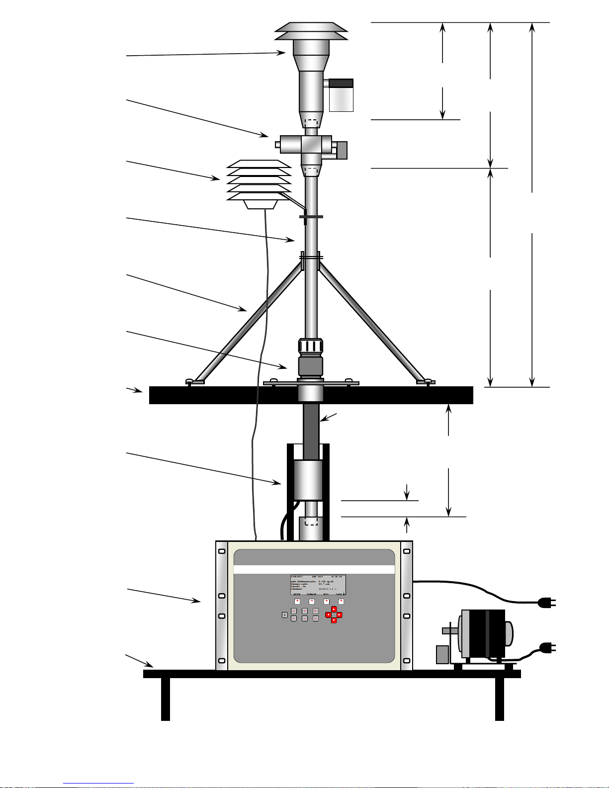
BX-802
PM10 Head
BX-806, BX-
807, BX-808
or BX-809
PM2.5 Cyclone
BX-596
AT/BP Sensor
(or BX-592)
Inlet Support
Struts
8112
Inlet Tube
8’ standard
BX-801
Roof Flange
Enclosure
Roof
BX-827 or 830
Smart Heater
with insulation
Mounting
Bench or Rack
2”
2 Meters
6.5 feet
adds
14.0”
adds
19.0”
BAM-1020
With Medo
vacuum pump or
equivalent
8” min. clearance
3 to 4 feet typical
5’ typical
BAM 1020
MET ONE INSTRUMENTS
Typical BAM-1020 Installation in a walk-in shelter
Pipe Insulation
(recommended)

BAM 1020-9800 Manual Rev W.docx Page 16
BX-802
PM10 Head
BAM 1020
MET ONE INSTRUMENTS
BX-806, BX-
807, BX-808
or BX-809
PM2.5 Cyclone
BX-596
AT/BP Sensor
(or BX-592)
27” Inlet Tube
2”
-Total Height-
6.6 ft (2.0 meters)
without cyclone
7.0 ft (2.1 meters)
with cyclone
adds
14.0”
adds
19.0”
15.5”
27” typical
Inlet tube
Mounting
Rack
BX-902 or 903
Environmental
Enclosure
BX-126
Vacuum Pump
or equivalent
BX-827 or 830
Smart Heater
with insulation
8119 Inlet
Seal
Typical BAM-1020 Installation in a BX-902 mini enclosure

BAM 1020-9800 Manual Rev W.docx Page 17
12.25”
BAM 1020
MET ONE INSTRUMENTS
14.25”
19”
17”
120 VOLTS
16”
5”min. rear clearance
74mm (2 15/16 “)
from front face of BAM
14mm (9/16”)
from center
CL
9.25”
3.5”
FRONT
BACK
TOP
BAM-1020 mounting dimensions
71mm (2 13/16 “)
from front of rack
Lifting Notes:
The main unit weighs slightly over 50 lbs,
with the center of mass near the front of
the BAM-1020. Lift by the rack rails or by
the bottom corner bracket. Observe
proper lifting and carrying techniques.
BAM 1020-9800 Manual Rev W.docx Page 18
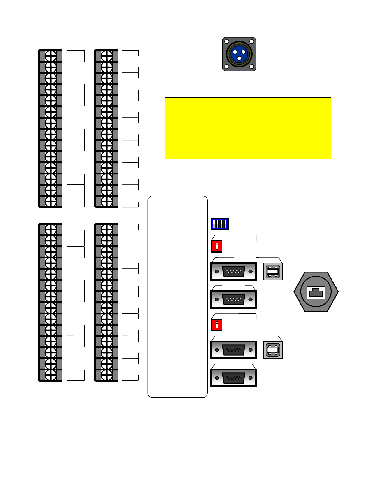
RELAY 1 NC
COMMON
COMMON
RELAY 1 NO
COM 3
REPORT
PRINTER
RS-232
OPTION
SWITCH
1 2 3 4
TELEMETRY
FAULT
NO VOLTAGE
SIGNAL
COMMON
POWER
ID
CHAN 1
SIGNAL
COMMON
POWER
ID
SIGNAL
COMMON
POWER
ID
SIGNAL
COMMON
POWER
ID
SIGNAL
COMMON
POWER
ID
SIGNAL
COMMON
POWER
ID
SIGNAL
COMMON
POWER
ID
EXTERNAL
RESET
NO VOLTAGE
+
EXTERNAL
RESET VOLTAGE
-
TAPE
FAULT
INVALID
DATA
MAINTENANCE
FLOW
FAULT
PUMP
CONTROL
POWER
FAIL
+
VOLTAGE
OUTPUT
-
CHASSIS
GROUNDS
+
CURRENT
OUTPUT
-
CHAN 2
CHAN 3
CHAN 5
CHAN 6
CHAN 7
CHAN 4
RS232
POLARITY
C1 NORMAL
C2 REVERSE
REPORT
POLARITY
C1 NORMAL
C2 REVERSE
SW1 OFF= 0-1V
SW1 ON= 0-10V
SW2 OFF= 0-16mA
SW2 ON= 4-20mA
SIGNAL
COMMON
POWER
SIGNAL
POWER
COMMON
NC
COMMON
NO
POWER
ID
SIGNAL 1
COMMON
SIGNAL 2
CHAN 8
CHAN 9
CHAN 10
RELAY 2
SMART
HEATER
Notes About Expanded Digital Ports:
There are several generations of the BAM-1020 digital port
configurations. Older units do not have the
REPORT, COM 3,
USB, or Ethernet
ports. The optional BX-965 Report Processor
back panel adds and enabled these data ports. Starting in 2012,
all units have these physical back panel connections, but they
are
not enabled unless the optional BX-965 daughter board
is installed inside the BAM
. Contact technical service for
further details.
BAM-1020 Rear Panel Connections
ETHERNET
BAM 1020-9800 Manual Rev W.docx Page 19
2.6 BAM 1020 Power and Electrical Service
The BAM 1020 uses internal 120V AC motors for the tape control system. The power supply
is factory-wired to run on either 110-120V or 220-240V, and either 50Hz or 60Hz. The
external vacuum pump and inlet heater are also AC powered and voltage-specific, and
should match the voltage setting of the BAM 1020. Note: The pump power cord is hardwired,
and may need to be replaced or adapted to match local outlet types outside of North
America.
Warning: Your shelter and/or electrical service must be wired for the correct voltage and
frequency in accordance with local electrical codes. Running the BAM 1020, vacuum pump,
or inlet heater on incorrect line voltage or frequency will cause improper operation.
The current draw of the system varies considerably depending on optional accessories and
environmental conditions. A dedicated 15 Amp electrical circuit is generally adequate to run a
single complete BAM 1020 system, unless a large air conditioner is on the same circuit.
Consult a qualified electrician if unsure. A summary of some worst-case loads is given below:
Model
Description
Amps
Wattage
BAM 1020
BAM 1020 only, 120V, worst case with tape transport motors running.
0.17A
20W
BX-126
Medo Linear Piston Pump, 120V, 60Hz, at 16.70 L/min through clean tape.
1.25A
150W
BX-121
Gast Rotary Vane Pump, 120V, 60Hz, at 16.70 L/min through clean tape.
4.44A
530W
BX-122
Gast Rotary Vane Pump, 230V, 50Hz, at 16.70 L/min through clean tape.
2.30A
530W
BX-827
Smart Inlet Heater, 120V, 60Hz, running at 100% high RH duty cycle.
0.85A
100W
BX-830
Smart Inlet Heater, 230V, 50Hz, running at 100% high RH duty cycle.
0.76A
175W
BX-902B
Shelter One Mini Shelter, 120V, worst case with shelter heater ON
4.2A
500W
BX-903
Ekto Mini Shelter, 120V, 2000 BTU air conditioner.
7.4A
586W
BX-904/906
Ekto Mini Shelter, 120V, 4000 BTU air conditioner.
13.5A
1172W
Notes:
•The BAM transport motors only run for a few seconds each per hour. Quiescent BAM current is 0.1A.
•The vacuum pump runs for either 42 or 50 minutes per hour. Startup inrush current is higher.
•Smart Heater wattage drops to idle at 20% (120V) or 6% (230V) when filter RH is below 35%.
•The BX-902B shelter heater is usually off whenever shelter temp is over 40 degrees F, and can be disabled.
•Values are based on measurements or best available information. Additional information is available from Service.
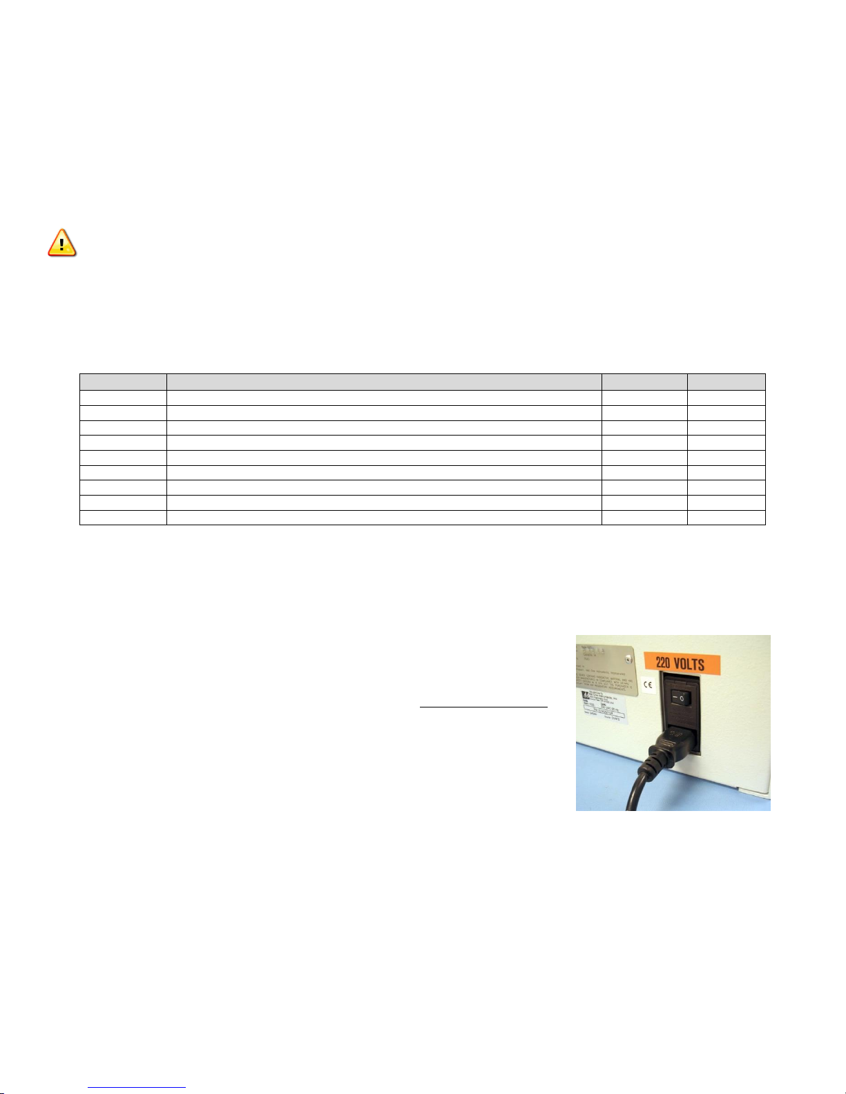
Fuses: There are two 5x20mm, 3.15A, 250V fuses located inside
the BAM 1020 power switch module on the back of the BAM
1020. They can be accessed by prying open the top of the small
cover surrounding the switch. The power cord must be removed
in order to open this cover.
Power Outages and Battery Backup: Any momentary AC
power outages will reset the BAM 1020 CPU and prevent data
collection for the sample hour. The BAM 1020 may be plugged
into a PC-style uninterruptible power supply (UPS) battery back-
up unit to prevent this. A UPS of at least 300 Watts is usually
sufficient. The vacuum pump does not need to be connected to the UPS, because the BAM
1020 can compensate for short pump flow outages of less than 1 minute duration. If the
pump is to be backed up, then a much larger UPS wattage is required.
Chassis Ground: Connect one of the terminals marked “CHASSIS” on the back of the BAM
1020 to an earth ground point using the green/yellow ground wire supplied with the BAM
1020. A copper earth-ground rod is recommended. The chassis ground is primarily for added
RFI/EMI noise immunity. The power cord also uses the standard electrical safety ground.

BAM 1020-9800 Manual Rev W.docx Page 20
3 INITIAL SETUP OF YOUR BAM 1020
This section describes the process for setting up and configuring your BAM 1020, as well as
the basic steps required to put the BAM 1020 into operation. Some of the topics in this
section will direct you to other sections of this manual for more detailed information. It is
assumed that the BAM 1020 is already installed and sited as described in Section 2. In some
cases it is useful to first set up the BAM 1020 on a test bench before deployment or
installation in order to explore the functions and perform setups. The following steps for
starting up your BAM 1020 are described in this section:
1. Power on and warm up.
2. Familiarize yourself with the user interface.
3. Load a roll of filter tape.
4. Perform a Self-Test.
5. Set the real-time clock, and review your SETUP parameters.
6. Perform a leak check and a flow check.
7. Return to the top-level menu and wait for automatic start at the top of the hour.
8. View the OPERATE menus during the cycle.
3.1 Power Up
The power switch is located on the back of the BAM 1020 above the power cord. Verify that
the BAM 1020 is plugged in to the correct AC voltage, and that any electrical accessories are
correctly wired before powering it up. (Section 2.6) When power is switched on, the main
menu screen should appear after a few seconds as shown below. The screen may flash an
error indicating that there is no filter tape installed. Note: Units running revision 3.1 or earlier
firmware will display a slightly different main menu screen.
3.2 Warm-up Period
The BAM 1020 must warm up for at least one hour before valid concentration data can be
obtained. This is because the beta detector contains a vacuum tube which must stabilize.
This also allows the electronics to stabilize for optimal operation. This applies any time the
BAM 1020 is powered up after being off for more than a moment. Instrument setups and filter
tape installation can be performed during this warm up time. You may consider discarding the
first few hours of data after the equipment is powered up.
3.3 The Main Menu and Using the Keypad and Display
When the BAM 1020 is powered up it will display the main menu (top level menu) on the LCD
display. This menu is the starting point for all functions of the BAM 1020 user interface. Note:
The main menu will have a slightly different layout on BAM 1020 units configured in the dual-
unit PM-coarse configuration.
Table of contents
Other Met One Laboratory Equipment manuals

Popular Laboratory Equipment manuals by other brands

Optika Italy
Optika Italy IM Series instruction manual

Thermo Scientific
Thermo Scientific CTS Xenon user guide

ERL
ERL tesla lite user manual

IKA
IKA Mini MR standard operating instructions

Four E's Scientific
Four E's Scientific Ironman III operating instructions

LW Scientific
LW Scientific BioVID instruction manual


