Metabo HO 18 LTX 20-82 User manual

www.metabo.com
HO 18 LTX 20-82
de Originalbetriebsanleitung 5
en Original instructions 10
fr Instructions d’utilisation originales 14
nl Originele gebruikaanwijzing 19
it Manuale d’uso originale 24
es Manual de instrucciones original 29
pt Manual de instruções original 34
sv Original bruksanvisning 39
fi Alkuperäiskäyttöohje 43
no Original bruksanvisning 47
da Original brugsanvisning 51
pl Oryginalna instrukcja obsługi 55
el Πρωτότυπο οδηγιών λειτουργίας 60
hu Eredeti használati utasítás 65
ru Оригинальное руководство по
эксплуатации 69

1.
2.
3.
12 3 4 5 768 910
11
12
13
14
16
17
18
A
6.30796
15
2

C
B
19
18
19
18
BA
21
21
22
21 21
19
(1,4 - 2,2 Nm)
(10-15 Nm)
(10-15 Nm)
1 mm
0 mm 0 mm
1 mm
20
20
20
24
21
23
23
26
21
26
23
25
19
20
24
22
23
21
25
21
3

4
HO 18 LTX 20-82
UV18
bmm (in) 82 (3 7/32)
tmm (in) 0 - 2,0 (0 - 1/16)
fmax mm (in) 9 (11/32)
lmm (in) 295 (11 5/8)
n0min-1 (rpm) 16000
mkg (lbs) 3,5 (8.0)
ah/Khm/s2< 2,5 / 1,5
LpA,KpA dB(A) 90 / 3
LWA,KWA dB(A) 101 / 3
13.
*1) Serial Number: 02082..
*2) 2014/30/EU, 2006/42/EC, 2011/65/EU
*3) EN 62841:2015, EN 62841-2-14:2015, EN IEC 63000:2018
2021-03-23, Bernd Fleischmann
Direktor Produktentstehung & Qualität (Vice President Product Engineering & Quality)
*4) Metabowerke GmbH - Metabo-Allee 1 - 72622 Nuertingen, Germany

ENGLISHen
10
Original instructions
We, being solely responsible, hereby declare that
these planers, identified by type and serial number
*1), meet all relevant requirements of directives *2)
and standards *3). Technical documents for *4) -
see page 3.
For UK only:
We as manufacturer and authorized person to
compile the technical file, see *4) on page 3,
hereby declare under sole responsibility that these
planers, identified by type and serial number *1) on
page 3, fulfill all relevant provisions of following UK
Regulations S.I. 2016/1091, S.I. 2008/1597, S.I.
2012/3032 and Designated Standards EN
62841:2015, EN 62841-2-14:2015, EN IEC
63000:2018.
The planer is ideal for planing and rabetting of wood
and for chamfering of the edges of wood and wood-
like materials.
The user bears sole responsibility for any damage
caused by inappropriate use.
Generally accepted accident prevention
regulations and the enclosed safety information
must be observed.
For your own protection and for the
protection of your electrical tool, pay
attention to all parts of the text that are
marked with this symbol!
WARNING – Reading the operating instruc-
tions will reduce the risk of injury.
WARNING – Read all safety warnings,
instructions, illustrations and
specifications provided with this power tool.
Failure to follow all instructions listed below may
result in electric shock, fire and/or serious injury.
Save all warnings and instructions for future
reference. Pass on your electrical tool only
together with these documents.
Wait for the cutter to stop before setting the
tool down. An exposed rotating cutter may engage
the surface leading to possible loss of control and
serious injury.
Use clamps or another practical way to secure
and support the workpiece to a stable platform.
Holding the workpiece by your hand or against the
body leaves it unstable and may lead to loss of
control.
Check the workpiece for foreign bodies. Remove
nails or other metal parts from the workpiece to be
processed.
Guide the tool against the workpiece only when it is
switched on. The planer’s sole must make secure
contact with the workpiece. Otherwise there is a risk
of rebound from jamming the tool in the workpiece.
Always get a secure grip of the machine when
switching on.
Always guide the machine with both hands on the
handles (2) and (6). Do not operate the machine in
a holder.
Danger of injury from sharp edges of the planer
knives.
Pay attention to the rotating cutter. Keep in mind
that the motor and thus also the cutter continue to
run after switching off the tool.
Do not put your body and hands near the cutter
drum.
Do not reach into the chip ejection mechanism.
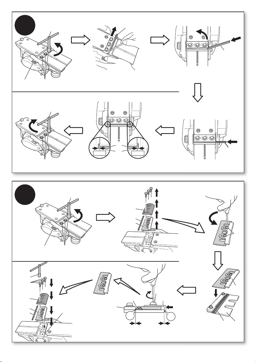
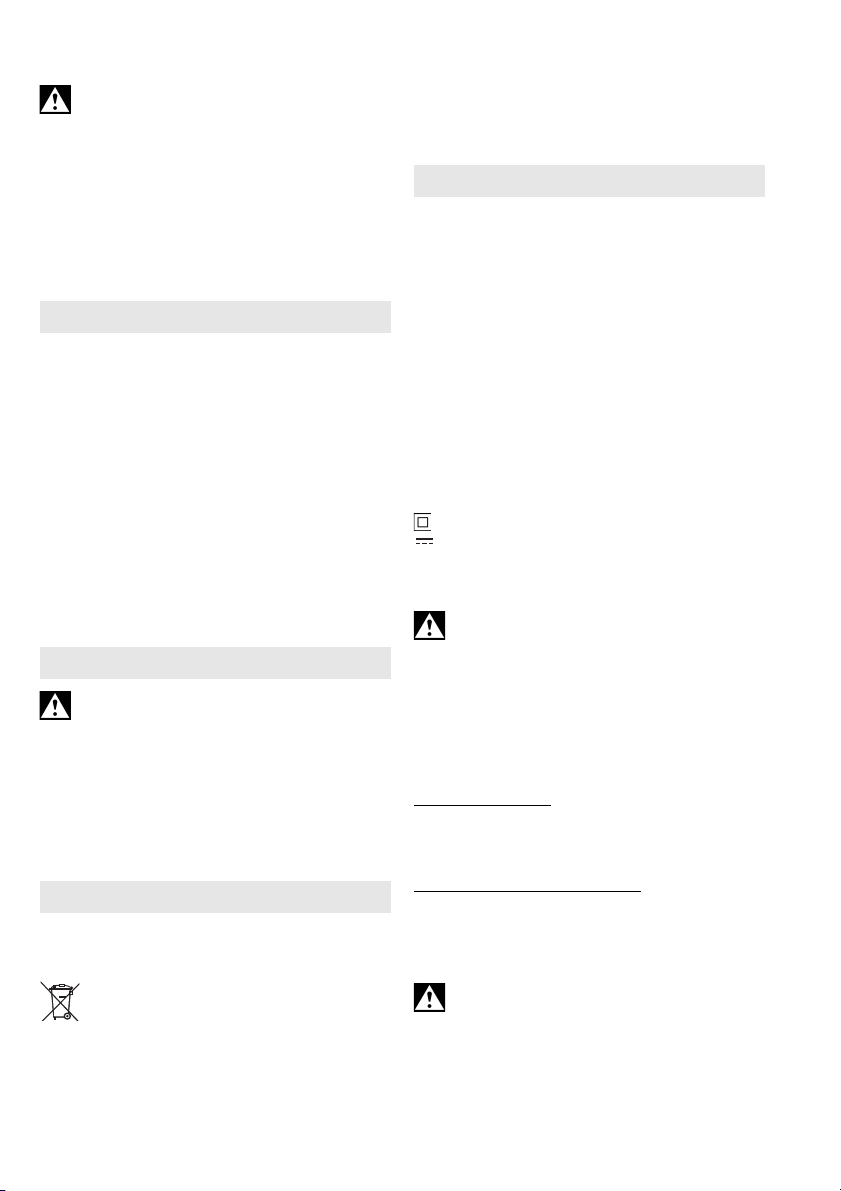
Reverse/replace blunt planer knifes in due time and
always in pairs: worn edges of the planer knifes
increase the risk of kickback and reduce the quality
of the planing work. Sharp planer knifes provide
good cutting output and reduce load on the
machine.
Put the planer down onto the stand (11). If the stand
is defective, have it repaired.
If the machine is defective, remove the battery pack
from the machine.
Remove the battery pack from the machine before
making any adjustments, changing tools,
maintaining or cleaning.
Protect battery packs from water and
moisture!
Do not expose battery packs to fire!
Do not use faulty or deformed battery packs!
Do not open battery packs!
Do not touch or short circuit battery pack contacts!
A slightly acidic, flammable fluid may leak
from defective Li-ion battery packs!
If battery fluid leaks out and comes into
contact with your skin, rinse immediately
with plenty of water. If battery fluid leaks out
and comes into contact with your eyes, wash them
with clean water and seek medical attention
immediately!
Transport of li-ion battery packs:
The shipping of li-ion battery pack is subject to laws
related to the carriage of hazardous goods (UN
3480 and UN 3481). Inform yourself of the currently
valid specifications when shipping li-ion battery
packs. If necessary, consult your freight forwarder.
Certified packaging is available from Metabo.
Only send the battery pack if the housing is intact
and no fluid is leaking. Remove the battery pack
1. Declaration of Conformity
2. Specified Conditions of Use
3. General Safety Information
4. Special Safety Instructions

ENGLISH en
11
from the machine for sending. Prevent the contacts
from short-circuiting (e.g. by protecting them with
adhesive tape).
Reducing dust exposure:
Some of the dust created using this power tool
may contain chemicals known to cause
cancer, allergic reaction, respiratory disease, birth
defects or other reproductive harm. Some of these
substances include: lead (in paint containing lead),
mineral dust (from bricks, concrete etc.), additives
used for wood treatment (chromate, wood
preservatives), some wood types (such as oak or
beech dust), metals, asbestos.
The risk from exposure to such substances will
depend on how long you or people nearby are
exposed to them.
Do not let particles enter the body.
Do the following to reduce exposure to these
substances: ensure good ventilation of the
workplace and wear appropriate protective
equipment, such as respirators able to filter
microscopically small particles.
Observe the relevant guidelines for your material,
staff, application and place of application (e.g.
occupational health and safety regulations,
disposal).
Collect the particles generated at the source, avoid
deposits in the surrounding area.
Use suitable accessories for special work. In this
way, fewer particles enter the environment in an
uncontrolled manner.
Use a suitable extraction unit.
Reduce dust exposure with the following measures:
- Do not direct the escaping particles and the
exhaust air stream at yourself or nearby persons
or on dust deposits.
- Use an extraction unit and/or air purifiers.
- Ensure good ventilation of the workplace and
keep clean using a vacuum cleaner. Sweeping or
blowing stirs up dust.
- Vacuum or wash the protective clothing. Do not
blow, beat or brush.
See page 2.
1 V-groove (for chamfering workpiece edges)
2 Knob handle (to set the planing depth, insulated
handle surface)
3 Scale (set planer depth in mm)
4Lockingbutton
5Trigger
6 Handle (insulated handle surface)
7 Battery pack release button
8 Battery pack *
9 Capacity and signal indicator
10 Capacity indicator button
11 Stand
12 Clamping screw of the parallel guide
13 Parallel guide
14 Outlet nozzle
15 Ejection nozzle
16 Extractor hose (extraction device)
17 Dust/chip collection bag
18 Chip ejection adapter
19 Drive belt
20 Fastening screws
21 Key
22 Planer knives
23 Cutter
24 Holder for planer knives
25 Mounting plate
26 Setting gauge
27 Screws of the planer knife holder
*equipment-specific
6.1 Battery pack
Charge the battery pack (8) before use.
Recharge the battery pack if performance
diminishes.
Instructions on charging the battery pack can be
found in the operating instructions of the Metabo
charger.
"Li-Power, LiHD" lithium ion battery packs have a
capacity and signal indicator (9):
- Press the button (10), the LEDs indicate the
charge level.
- The battery pack is almost flat and must be
recharged if one LED is flashing.
Removing and inserting the battery pack
Remove: Press the battery pack release button (7)
and remove battery pack (8) .
To insert: Slide the battery pack (8) in until it
engages.
6.2 Dust/chip extraction
Third-party extraction units
Connect a suitable extraction device to the ejection
nozzle (14).
For optimal dust extraction, use the connecting
sleeve 6.30796.
Own extraction system
Fit dust / chip collection bag (17) to the ejection
nozzle (14) . Empty the dust / chip collection bag
(17) in good time to optimise dust extraction.
Chip ejection
If you work without extraction device or without dust/
chip collection bag: (17) Fit chip ejection adapter
(18) and turn into the desired position.
If the outlet nozzle (14)tends to clog often
(depending on the material and operation), we
recommend unscrewing the outlet nozzle (14) and
to attach the ejection nozzle (15). Note: The parts
(16), (17), (18) cannot be attached to the ejection
nozzle (15).
5. Overview
6. Initial Operation

ENGLISHen
12
7.1 Setting the planing depth
By turning the knob handle (2) the planing depth
can be set steplessly.
Read the set planing depth on the scale (3).
Set the planing depth only in the range of 0 -
2.0 mm.
7.2 Switching on and off
Switching on: Press and hold in the locking button
(4) , then actuate the trigger (5) .
Switching off: Release the trigger switch (5).
7.3 Working Directions
General notes
For coarse work set a large planing depth and push
the machine forward with a suitable, reduced feed
speed so that the shavings are ejected uniformly
from the machine.
To obtain a smooth workpiece surface, set a low
cutting depth and slowly and uniformly advance the
planer.
1. Setting the planing depth.
2. Tightly hold the machine with both hands at the
handles (2) and (6).
3. Place the front part of the planer evenly on the
workpiece.
At the start of the workpiece, press the front part
of the planer on the workpiece. See page 2, fig.
A.
4. Switch on first, then guide the accessory
towards the workpiece.
5. Guide the machine forwards in a slow and
uniform manner.
6. The stand (11) is swivelled upwards by the
workpiece edge.
7. At the end of the workpiece, press the rear part
of the planer on the workpiece. See page 2, fig.
A.
Chamfering edges
The V-groove (1) makes chamfering workpiece
edges easier.
Place the machine with V-groove (1) on the
workpiece edge. Guide the machine forwards in a
slow and uniform manner on the edge.
Planing with parallel guide
Insert the parallel guide, (13) from the left. Push into
the desired position and tighten the clamping screw
(12).
When planing, the parallel guide (13) must make
contact with the workpiece.
Remove the battery pack from the machine
before making any adjustments, changing
tools, maintaining or cleaning.
Danger of injury from sharp edges of the
planer knives.
The cutter continuesrunning after the machine
has been switched off. Wait for the standstill of
the cutter.
Reverse/replace planer knives (22) that have
turned blunt (see page 3, fig. B)
1. Turn the drive belt (19) until the planer knife is
accessible.
2. Fastening screws (20) (21) must be loosened
(not unscrewed) with key.
3. Using a piece of wood, push the planer knife (22)
out from the side (see arrow in fig.).
4. Insert reversed/new planer knife (22). (order no.
see chapter 10. accessories).
5. Centrally align the planer knife (22): It protrudes
the cutter (23) on the right and left by 1 mm
respectively.
6. Firmly tighten (10-15 Nm) the fastening screws
(20) with key (21) - the central fastening screw
first.
7. Also reverse/replace the second planer knife.
ONLY IF NEEDED:
Adjust the holder of the planer knife (24) (see
page 3, fig. C)
The holder of the planer knife (24) comes correctly
adjusted from the factory. In case it got misaligned,
adjust it as follows:
1. Turn the drive belt (19) until the planer knife is
accessible.
2. Fastening screws (20) (21) must be loosened
with key.
3. Remove mounting plate (25).
4. Remove planer knife (22) and planer knife
holder (24) .
5. Loosen the screws (27).
6. Position the planer knife holder (24) (as shown)
on the setting gauge (26):
Align in such a way that the planer knife holder
(24) makes contact with spot A and at the same
time the planer knife (22) makes contact with
spot B at the setting gauge (26). See figure!
7. Tighten (1,4 - 2,2 Nm) both screws (27).
8. Insert planer knife holder (24) and planer knife
(22) (as shown) in the cutter (23) and align
centrally.
9. Position the mounting plate (25) (as shown) and
firmly tighten (10-15 Nm) the fastening screws
(20) with a key (21) - the central fastening screw
first.
10.If required, also adjust the second planer knife
holder (24).
Remove the battery pack from the machine
before making any adjustments, changing
tools, maintaining or cleaning.
Danger of injury from sharp edges of the
planer knives.
The cutter continuesrunning after the machine
has been switched off. Wait for the standstill of
the cutter.
7. Use
8. Maintenance
9. Troubleshooting, cleaning

ENGLISH en
13
Clogged ejection nozzle
Use a suitable tool, e.g. a piece of wood to
clean a clogged ejection nozzle (14). Do not
reach into the ejection nozzle (14).
If the outlet nozzle (14)tends to clog often
(depending on the material and operation), we
recommend unscrewing the outlet nozzle (14) and
to attach the ejection nozzle (15). Note: The parts
(16), (17), (18) cannot be attached to the ejection
nozzle (15).
Clean the machine regularly. Remove chip
ejection adapter (18) and clean e.g. with a cloth.
Vacuum clean the ventilation louvres on the motor.
Use only original Metabo or CAS (Cordless Alliance
System) battery packs and accessories.
Use only accessories that fulfil the requirements
and specifications listed in these operating
instructions.
A Carbide reversible planer knife
Order no.: 6.30282 (2 pieces)
Order no.: 6.30272 (10 pieces)
B Chargers: ASC ultra, ASC 30-36, ASC 15, etc.
C Battery packs with different capacities. Only buy
battery packs only with voltage suitable for your
power tool:
4.0 Ah (6.25591), 5.2 Ah (6.25592), 5.5 Ah
(6.25342), 6.2 Ah (6.25341), 7.0 Ah (6.25345),
etc.
For a complete range of accessories, see
www.metabo.com or the catalogue.
Repairs to electrical tools must ONLY be
carried out by qualified electricians!
The drive belt cable must only be replaced by
Metabo or an authorised customer service
workshop.
Contact your local Metabo representative if you
have Metabo power tools requiring repairs. See
www.metabo.com for addresses.
You can download a list of spare parts from
www.metabo.com.
Observe national regulations on environmentally
compatible disposal and on the recycling of disused
machines, packaging and accessories.
Only for EU countries: never dispose of
power tools in your household waste! Used
power tools mustbe collected separately and
handed in for environmentally compatible recycling
in accordance with European Directive 2012/19/EU
on waste electrical and electronic equipment and its
implementation in national legal systems.
Battery packs may not be disposed of with regular
waste. Return faulty or used battery packs to your
Metabo dealer!
Do not allow battery packs to come into contact with
water!
Discharge the battery pack in the power tool before
disposal. Prevent the contacts from short-circuiting
(e.g. by protecting them with adhesive tape).
Explanatory notes on the specifications on page 3.
Subject to change in accordance with technical
progress.
U = Voltage of battery pack
P1=Ratedinputpower
P2= Power output
b=Planingwidth
t = adjustable planing depth
fmax = Largest rabbetting depth
l = Length of the planer’s sole
n0=Idlespeed
m = Weight with smallest battery pack
Measured values determined in conformity with
EN 62841.
Permitted ambient temperature during operation:
-20 °C to 50 °C (limited performance with
temperatures below 0 °C). Permitted ambient
temperature for storage: 0 °C to 30 °C
Machine in protection class II
Direct current
The technical specifications quoted are subject to
tolerances (in compliance with the relevant valid
standards).
Emission values
These values make it possible to assess the
emissions from the power tool and to compare
different power tools. The actual load may be higher
or lower depending on the operating conditions, the
condition of the power tool or the accessories.
Please allow for breaks and periods when the load
is lower for assessment purposes. Arrange
protective measures for the user, such as
organisational measures based on the adjusted
estimates.
Vibration total value (vector sum of three directions)
determined in accordance with EN 62841:
ah= vibration emission value
(Planing soft wood)
Kh= Uncertainty (vibration)
Typical A-weighted sound levels:
Lpa = Sound-pressure level
LWA =Acousticpowerlevel
KpA, KWA = Uncertainty
The noise level can exceed 80 dB(A) during
operation.
Wear ear protectors!
10. Accessories
11. Repairs
12. Environmental Protection
13. Technical Data
Other manuals for HO 18 LTX 20-82
1
Table of contents
Other Metabo Planer manuals

Metabo
Metabo HO 18 LTX 20-82 User manual

Metabo
Metabo HC 300 Manual

Metabo
Metabo Routers and Planers Manual

Metabo
Metabo HO 26-82 User manual

Metabo
Metabo HC 260 C User manual

Metabo
Metabo HC 260 C User manual

Metabo
Metabo 602082840 User manual

Metabo
Metabo DH 330 User manual

Metabo
Metabo HC 410 User manual

Metabo
Metabo HC 260 M User manual