Metacon-Next RGS EI-30 User manual
User Manual
Metacon-Next RGS EI(1) 30 - EI(2) 60 - EW 240
This is a manual translated into English
Metacon-Next B.V.
Zuidbaan 450
2841 MD Moordrecht
The Netherlands
Tel. : +31 (0) 182 23 15 25
www.metacon-next.com
Metacon-Next B.V.
Randweg 19
8304 AS Emmeloord
The Netherlands
+31 (0) 182 23 15 25
www.metacon-next.com

Metacon-Next B.V. RGS EI(1) 30 - EI(2) 60 - EW 240 12-07-2022
User Manual art no: 89072 Rev: 1
2
1Preface.....................................................................................................................................................3
2Introduction............................................................................................................................................. 4
3Safety....................................................................................................................................................... 5
3.1 Safety Features ...................................................................................................................................... 5
3.2 Safety guidelines.................................................................................................................................... 6
3.3 Residual risks ......................................................................................................................................... 7
4Usage instructions ...................................................................................................................................8
4.1 Normal use (not during fire alarm/calamity) ........................................................................................ 8
4.2 Self-closing function............................................................................................................................... 9
4.3 Actions after improper use .................................................................................................................... 9
5Technical Specifications ...........................................................................................................................9
6Product....................................................................................................................................................9
7Installation preparation......................................................................................................................... 10
7.1 Essential tools for installation.............................................................................................................. 10
8Installation Instructions ......................................................................................................................... 11
9Initial use ............................................................................................................................................... 25
10 Maintenance, faults and repairs ............................................................................................................ 25
10.1 Regular maintenance........................................................................................................................... 25
10.2 Cleaning ............................................................................................................................................... 25
10.3 Faults and repairs ................................................................................................................................ 25
11 Storage and transport............................................................................................................................ 26
12 Environment and disposal...................................................................................................................... 26
Appendix A: " RGS EI(1) 30 - EI(2) 60 - EW 240 - Installation data" ................................................................. 27
Appendix B: "RGS EI(1) 30 - EI(2) 60 - EW 240 - Maintenance Instructions".................................................... 28
Appendix C: "RGS EI(1) 30 - EI(2) 60 - EW 240 - Maintenance Log" ................................................................. 29

Metacon-Next B.V. RGS EI(1) 30 - EI(2) 60 - EW 240 12-07-2022
User Manual art no: 89072 Rev: 1
3
1Preface
Before using the door, please observe the safety instructions in this document and the
instructions for use.
Metacon-Next only supplies products to the "specialist retailers". This means that Metacon-
Next only delivers a door. The installation, service and maintenance by and under the
responsibility of the "specialist retailer" is taken care of.
Metacon-Next only supplies CE marked doors in accordance with EN 13241 and/or EN
16034.
If assembly and installation of the fire resistant door is done by third parties and changes are
made to the door by the installation company, this shall be done with material supplied by
Metacon-Next, registered under the serial number of the door.
When the installation company makes this modification in accordance with the current
European legislation, it is obliged to mark the installation CE itself.
It is the responsibility of the installation company to install the door in accordance with the
operating instructions. The operating instructions should remain with the door at all times.
Type marking with the serial number is attached at the following location: On the drive side
on the guide, approximately 1600mm from the bottom. This sticker must not be removed or
covered, this information is required for the supply of repair and/or maintenance items,
among other things.
Metacon-Next shall not be liable for unsafe conditions, accidents, damages and injuries
resulting from, for example:
Disregarding warnings and/or regulations as displayed on the fire resistant
door and/or in the owner's manual;
Insufficient and/or improper maintenance, Metacon-Next sets a minimum
frequency of once a year maintenance as necessary;
Modifications to the door and accessories by third parties. This also includes
the use of other than prescribed replacement parts (e.g. a battery), incorrect
connection or setting, modification of the control unit and control program.
Improper installation or assembly of the product.
Local (country specific) additional regulations.

Metacon-Next B.V. RGS EI(1) 30 - EI(2) 60 - EW 240 12-07-2022
User Manual art no: 89072 Rev: 1
4
Reference documents:
-EN 13241-1; EN 16034;
-Terms and Conditions of the Metaalunie;
-Installation Drawing Metacon-Next;
-Package receipt with item numbers;
-User manuals from the motor and controller supplier;
-User manuals of any included accessories;
-DoP (Declaration Of Performance).
The installation company must follow all instructions in the installation instructions.
The user must follow all instructions in the user manual. The user manual should be
handed over to the user upon completion to be left at the door.
© COPYRIGHT
Metacon-Next B.V. holds the copyright for this manual. All worldwide rights
reserved. It is not permitted to copy, duplicate, translate, edit and store this manual
or portions thereof in any electronic medium without prior written permission from
the copyright holder.
2Introduction
This fire resistant door is mainly intended to separate interconnected spaces (fire
compartments) in case of fire and/or smoke development. The purpose of this is to prevent
the fire from spreading to other rooms and/or adjacent properties. The fire resistant door
can be controlled by a fire alarm system but can also be controlled by a stand-alone alarm
system.
The CE marking that is issued is only valid for those performances that are stated in the
Declaration Of Performance (DoP), which is supplied with each door.
In accordance with the EN 12635 standard, in this document, after the instructions for use,
the installation instructions and regulations for first use will follow.

Metacon-Next B.V. RGS EI(1) 30 - EI(2) 60 - EW 240 12-07-2022
User Manual art no: 89072 Rev: 1
5
3Safety
When installing the fire resistant door, the (safety) regulations applicable to the situation
must be observed, for example, the Working Conditions Act. in addition to the regulations,
the instructions in this document must be strictly followed. When installing electrical
components, the instructions supplied by the manufacturer of these components must be
observed.
Since Metacon-Next is only a manufacturer/supplier of "semi-finished products," it is the
responsibility of the installation company to ensure that they work in accordance with the
relevant instructions and regulations.
Any damage or injury incurred as a result of non-compliance with this user manual,
maintenance instructions and improper use cannot be recovered from the fire resistant door
manufacturer.
3.1 Safety Features
The installation may be equipped with the following safety devices.
Roll-off / fall protection / slack cable protection / crushing protection / switching
protection.
Smoke and temperature detectors and/or fire alarm system.
Shielding below 2500 [mm] from an accessible floor, mandatory in case of a crushing
hazard (NEN-EN 294);
ATEX components, if applicable, see additional manual/instruction
See the product specifications in Chapter 5 for installed features.

Metacon-Next B.V. RGS EI(1) 30 - EI(2) 60 - EW 240 12-07-2022
User Manual art no: 89072 Rev: 1
6
3.2 Safety guidelines
The fire resistant door may only be operated by persons who have taken note of the
operating instructions. Under no circumstances may the door be operated by
children or persons with reduced physical, sensory or mental capacity. The door may
only be used in the manner described in section 4.1.
The fire resistant door is designed so that the door will always close mechanically
failsafe in the event of a fire or smoke alarm. During mechanical failsafe the door will
not signal persons and/or materials, in accordance with EN 13241 an optical and
acoustic warning signal will be activated. (Exceptions to this rule are possible in
consultation with or after approval by the competent authority, the installation
company or end user must arrange for this approval to be granted).
In exceptional situations, the fire resistant door can be supplied with a non-
mechanical failsafe system, this door should be closed at all times, it can be used as a
passage but should then immediately close again.
When the door is installed in an escape route ensure that the door is suitable for
intended use (escape door). (EN 16034-2) (EN 14351-1 and 2)
In the case of hold-to-open/hold-to-close operation, the control switch must be
positioned so that the operator has a clear view of the opening/closing of the door.
Before operating, check that there is no visible damage to the door, if damage is
found the supplier should be asked to repair the damage, a door with damage should
not be operated.
Before and during operation, check that there are no other persons within an area of
±2 [m] of the door.
Before and during operation, check that there are no obstacles under the door.
During maintenance/inspection of the fire resistant door the installation must be
powered down and ensure that it remains powered down.
Prevent entrapment of persons in the room. If persons are still present, the door
should remain open if there is no means of escape.
When using a mechanical failsafe motor, the door will close immediately upon power
failure unless a backup system is present, it will hold the door open until a fire alarm
is activated or after the critical voltage of the backup system is reached.
We recommend that the installation be grounded, with an ATEX version this is
mandatory.

Metacon-Next B.V. RGS EI(1) 30 - EI(2) 60 - EW 240 12-07-2022
User Manual art no: 89072 Rev: 1
7
3.3 Residual risks
In case of regular use:
Entrapment can occur when the fire resistant door closes upon fire alarm. The
mechanical failsafe closing of the fire resistant door does not take into account the
possible presence of persons. The probability of a person becoming trapped is very
low due to the low speed of the closing movement and the optical and acoustic
warning signals.
When a gravitational self-closing (failsafe) system on our products / the fire resistant
doors, 2 optical and 1 acoustic signals with autonomous power supplies will be
provided in accordance with standard EN 12604-2000 / EN 13241-2016;
It is strictly forbidden to place goods/materials in the "run" of the closing and/or opening
door leaf.
In case of maintenance:
During maintenance/inspection of the fire resistant door the installation must be
disconnected from the power supply and ensure that it remains disconnected from
the power supply. Due to voltages in the installation there remains a risk of electric
shock.
Upon inspection of the movement system, crushing hazard may occur when the door
comes/is in motion.

Metacon-Next B.V. RGS EI(1) 30 - EI(2) 60 - EW 240 12-07-2022
User Manual art no: 89072 Rev: 1
8
4Usage instructions
4.1 Normal use (not during fire alarm/calamity)
Before and during the operation of the door, the following steps should be observed;
Before you operate the door, you should take note of the safety instructions in
Chapter 3.
Check that there is nothing or no one around, against or under the door while
operating the door, do not start or stop operating the door immediately if there is.
You operate the door by means of the control device, usually push buttons or a key
switch. While operating the door, you stay at a sufficient distance but within sight of
the moving part of the door, 2-8 mtr.
Make sure that while operating the door, it actually moves in the correct direction, if
it does not, stop operating and/or press the stop button and contact the supplier
immediately.
Keep a view of the door at all times during movement.
Make sure the door is fully opened when opening and fully closed when closing to
promote durability.
If irregularities are detected while operating the door, stop operating and contact the
supplier. Possibly an unsafe situation arises, cordon off the area so that the
passageway cannot be used, e.g., if the door is not fully opened or closed.
The door can be protected against entrapment of objects and/or persons in several ways.
NOTE: Holding the control will override the protection.
In the case of hold-to-open/hold-to-close operation, the door will stop immediately
after releasing the control.
If an safety edge protection function is present, the door will automatically go back
up after contact with an object and/or a person. Possibly a set of photocells can be
added to the safety edge protection function.
When a set of photocell curtains is installed, the door will not close when the sensor
detects an object in the path of this security. Please note that this only works in the
line/area of the security sensor. No object and/or person will be detected outside of
this.
Note that safety devices are not designed to operate the door!
In order to put the door back into operation after a safety edge/ photocell curtains has been
triggered, you must remove the objects and/or persons from the detection area of the safety
edges.

Metacon-Next B.V. RGS EI(1) 30 - EI(2) 60 - EW 240 12-07-2022
User Manual art no: 89072 Rev: 1
9
4.2 Self-closing function
If the door is in the open position at the moment of "activation" by an (automated) alarm
system and mains power failure, it will close automatically. This is done by means of an
electric drive with a gravitational failsafe system.
A gravitational failsafe system means that the door can still close by gravity after the
failure/loss/breakdown of the electrical facilities. This movement is controlled by a speed
limiter. In case of "control" the door will not take into account objects/people under the
door and will close immediately.
Optionally, the photocell curtains can be kept temporarily active and closed after a set time
with a force lock.
It is strictly forbidden to place goods/materials in the "run" of the closing and/or opening
door leaf.
4.3 Actions after improper use
If an object has become trapped under the door, and the door has come to a stop as a result,
perform the following actions.
Move the door up carefully, until you can remove the object.
After the object is removed, you must close the door completely.
Perform a visual inspection before sending the door open.
If in doubt or if any of these actions fail, contact the supplier.
5Technical Specifications
Please refer to the order confirmation and/or packing slip.
6Product
Please refer to the product leaflet and the optional BOM (Bill Of Material)

Metacon-Next B.V. RGS EI(1) 30 - EI(2) 60 - EW 240 12-07-2022
User Manual art no: 89072 Rev: 1
10
7Installation preparation
Before the installation of the door can be started, the following items should be checked:
Before the installation can begin, the installation company must have familiarized
themselves with the contents of this user manual.
It is the responsibility of the installation company to be aware of the local regulations
concerning the installation of the door (e.g. Working Conditions Act).
Check the work area for accessibility and work space, then cordon off the work area.
Note the following points:
-Check the clear width and height and the available side and top space, the
dimensions according to Technical Drawing are leading.
-Check the mounting surface for obstructions.
-Check that the surface is level for installation as indicated on the technical
drawing.
-Check that the walls, floor and lintel are perpendicular and straight as shown
on the technical drawing.
-Check that the correct electrical connections are present as shown on the
technical drawing.
-Assess whether the substrate offers sufficient strength for the construction, if
in doubt contact the supplier.
Check all parts against the packing slip and/or order confirmation, and/or refer to the
list of all parts against the optional BOM (Bill Of Material) of the user manual.
7.1 Essential tools for installation
The required tools cannot be determined by Metacon-Next, as this depends on the
installation situation. It is up to the supplier and/or installation company to determine the
appropriate tools.

Metacon-Next B.V. RGS EI(1) 30 - EI(2) 60 - EW 240 12-07-2022
User Manual art no: 89072 Rev: 1
11
8Installation Instructions
After the installation company has been prepared according to chapter 7, the installation of
the door can begin.
Important: Fasteners are optionally provided by Metacon-Next. Use only fasteners
suitable for the intended strength and fire resistance and appropriate to the substrate.
Follow the instructions of the fasteners supplied.
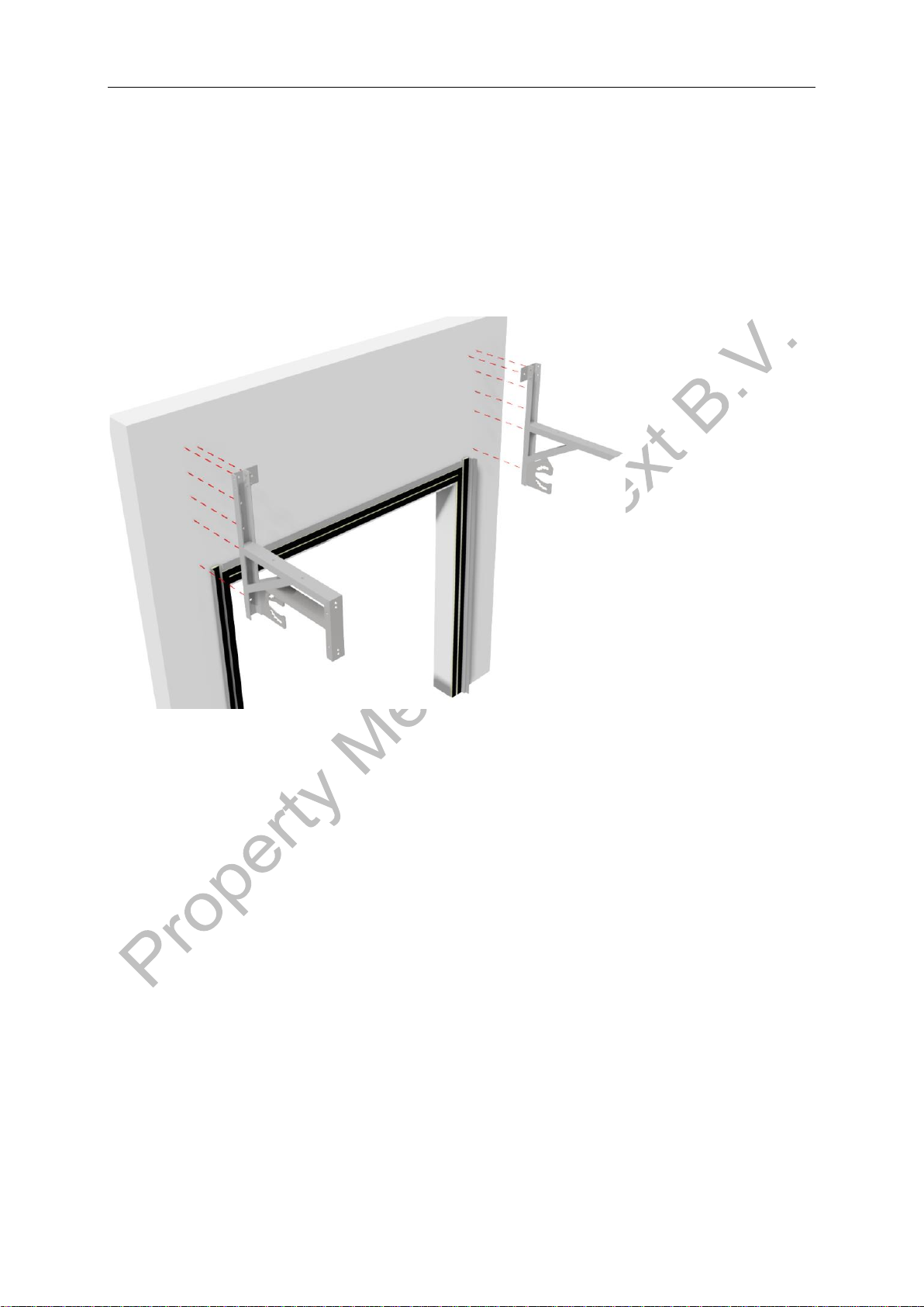
Step 1: Mounting side guides
Mount the side guides to the width according to Technical Drawing Metacon-Next. Check
the width. Check that the side guides are installed parallel and level.

Metacon-Next B.V. RGS EI(1) 30 - EI(2) 60 - EW 240 12-07-2022
User Manual art no: 89072 Rev: 1
12
Step 2: Mounting horizontal wall labyrint
Mount the horizontal wall labyrint at the correct height according to Technical
Drawing Metacon-Next. Spread the space between the horizontal wall labyrint and
the guides left and right so that it is equal.
Step 3: Use drilling template
Place the drilling template against and on the guide as shown in the drawing below.
Make sure it is level, mark the hole pattern and remove the drilling jig. Then drill the
holes. (Top inward part of the template is optional)
Metacon-Next B.V. RGS EI(1) 30 - EI(2) 60 - EW 240 12-07-2022
User Manual art no: 89072 Rev: 1
13
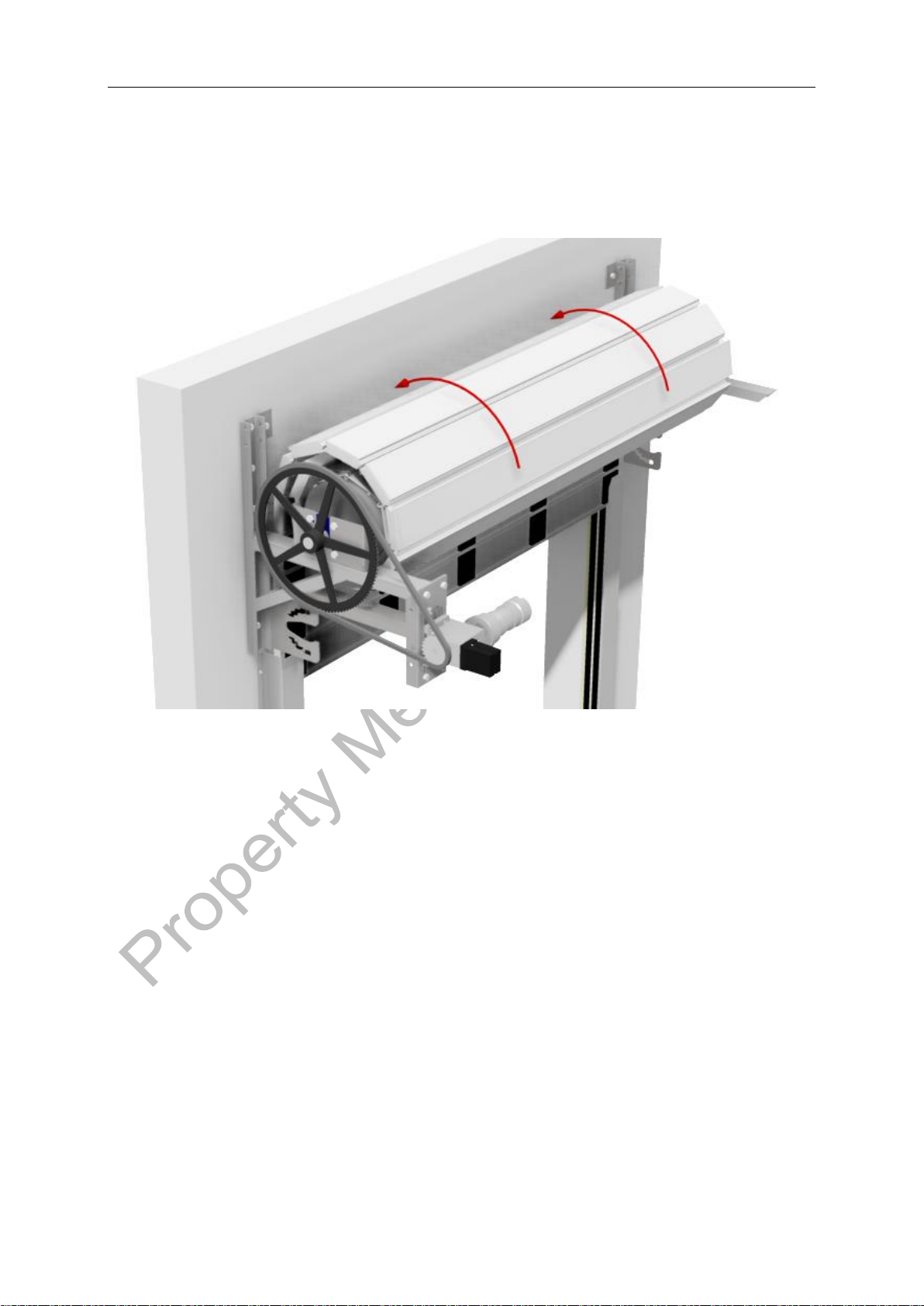
Step 3b: Mounting of brackets
Remove the tensioner (motor bracket) and L-profile in order to obtain sufficient mounting
space to install the rolled-up curtain.
If adjustment brackets for the bearings are provided, the marking arrow should
always point towards the wall. Mount the UNP brackets with the pressure roller
plates inwards. Make sure the brackets are level, parallel and perpendicular to the
wall. Check that the brackets connect with the guides and the wall.

Metacon-Next B.V. RGS EI(1) 30 - EI(2) 60 - EW 240 12-07-2022
User Manual art no: 89072 Rev: 1
14
Step 4a: Preparations for installation of curtain + barrel
Degrease and oil the shaft journals before mounting the bearings onto them.
Slide the roll-down protection over the shaft and key using the correct direction of
rotation.
ATTENTION: Check that the roll-down protection is not blocked. If this is the case, it must
be repaired! See Roll-down Protection Data Sheet for further instructions.
On the other side, place the bearing over the shaft.
Tighten one locking screw of the bearing by hand to prevent sliding.
Note: The figure below is for a situation with the drive on the left.
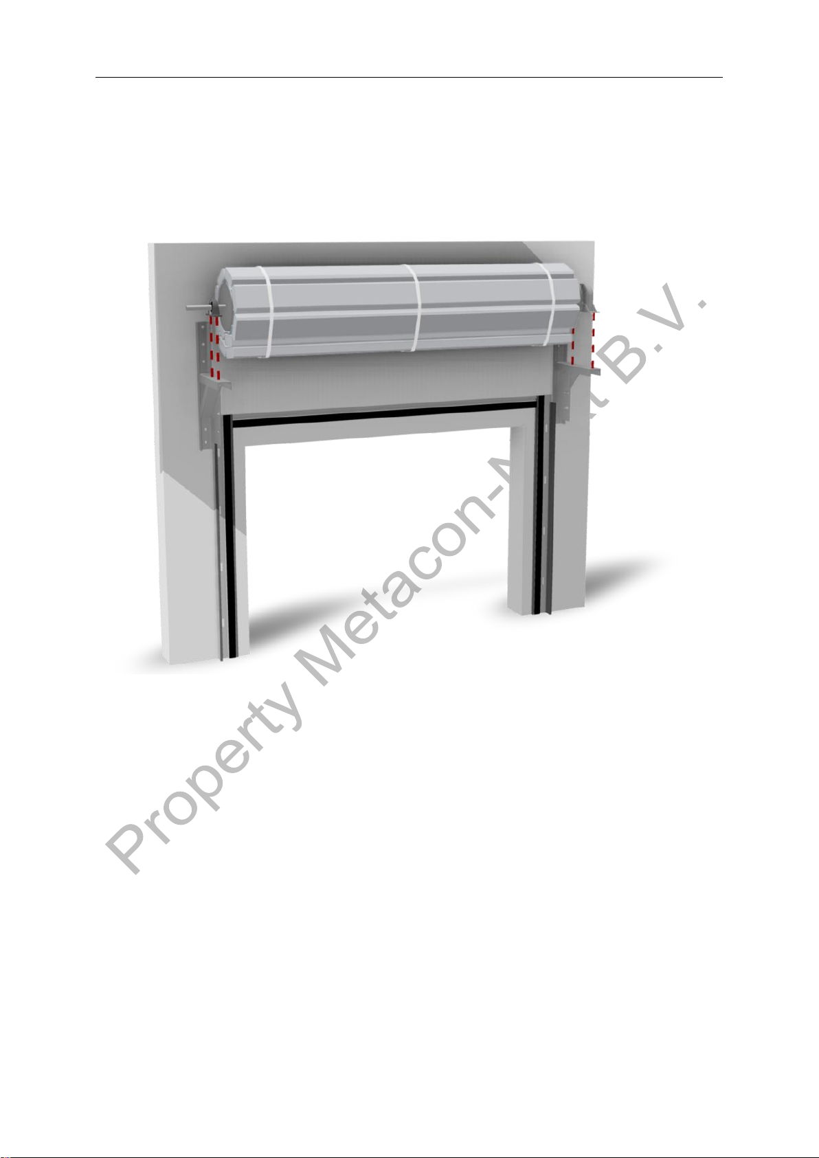
Step 4b: Mounting the curtain + barrel
Place the forks of the forklift at +/- 1/3rd of the width of the curtain (this may require
a 2nd forklift), paying attention to possible support points marked on the pallet. Raise
the whole thing using the right lifting equipment. Position the bearings above the
brackets and lower them in a controlled manner.
ATTENTION: Check that the roll-down protection is not blocked. If this is the case, it must
be repaired! See Roll-down Protection Data Sheet for further instructions.
Metacon-Next B.V. RGS EI(1) 30 - EI(2) 60 - EW 240 12-07-2022
User Manual art no: 89072 Rev: 1
15
Step 4c: Mounting the curtain + barrel
Check that the shaft is mounted parallel to the wall. Divide the space between the
barrel and the brackets left and right. Tighten the mounting bolts and the locking
screws of the bearings.

Metacon-Next B.V. RGS EI(1) 30 - EI(2) 60 - EW 240 12-07-2022
User Manual art no: 89072 Rev: 1
16
Step 5: Mount the sprocket wheel
On the motor side, insert the key into the shaft. Then slide the sprocket wheel onto
it with the front side facing away from the roller.
Metacon-Next B.V. RGS EI(1) 30 - EI(2) 60 - EW 240 12-07-2022
User Manual art no: 89072 Rev: 1
17
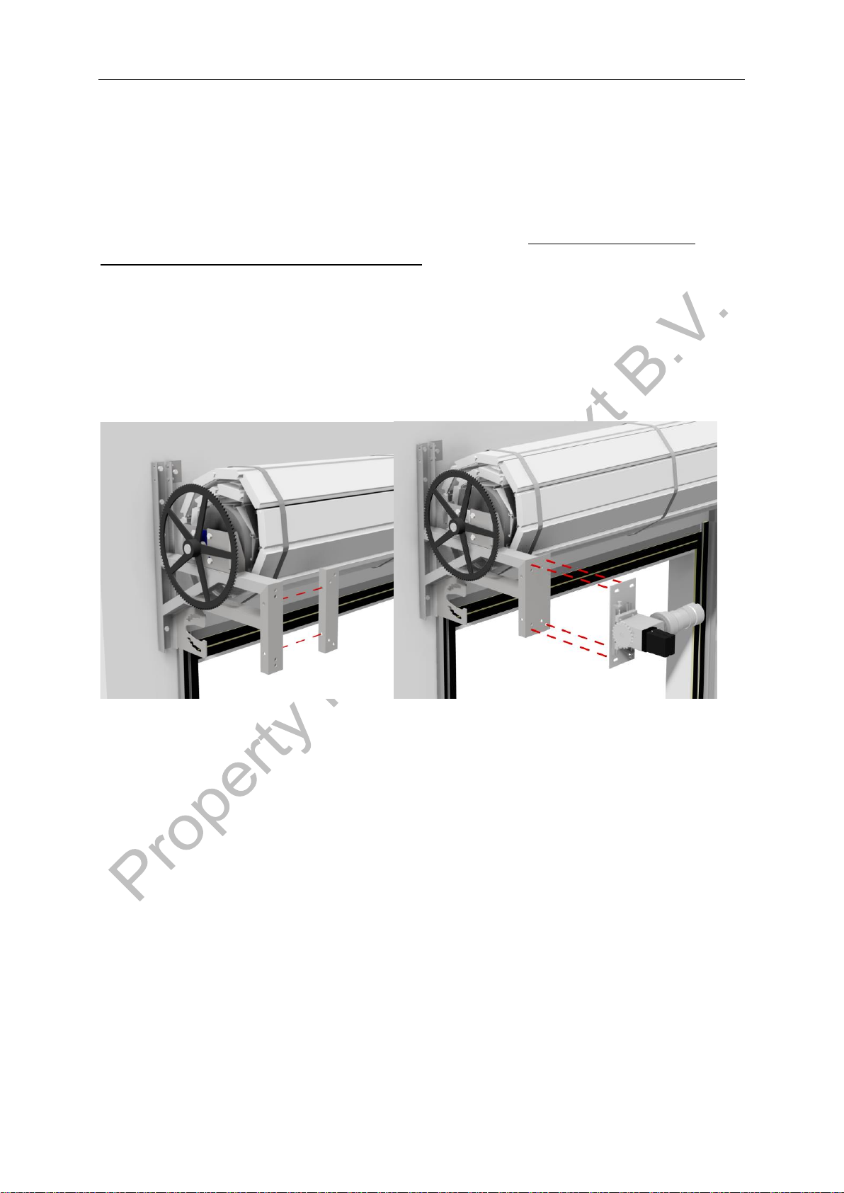
Step 6a: Mounting of motor and tensioner (motor bracket)
Check that the limit switch housing is in the correct position: it should not touch the chain.
Mount the control box and connect it to the power supply including the battery (if supplied)
and the roll-down protection.
Attention: any other components may only be connected in step 10 of this manual!
Check that the direction of rotation corresponds to the knobs in the control box at the
connection to which the door is to be adjusted.
Place the sprocket wheel onto the motor shaft with the front side facing the motor.
The motor can now be mounted onto the tensioner with the corner strip, with the supplied
fasteners in the middle position of the tensioner’s (motor bracket) adjustment range.
Mount it against/onto the bracket.
Align sprocket wheels both horizontally and vertically, and secure them with the
locking screws.

Metacon-Next B.V. RGS EI(1) 30 - EI(2) 60 - EW 240 12-07-2022
User Manual art no: 89072 Rev: 1
18
Step 6b: Installation and tensioning of the chain
Place the chain over the sprocket wheels and mark the required length, then remove the
chain.
Cut the chain to the right length and place it on the sprockets using the supplied shackles.
When tensioning the chain, make sure that it is not overtightened.
If the chain tension is insufficient, the roll-down protection can be activated due to the slack
in the chain.
After tensioning the chain, check that the sprocket wheels are still correctly aligned.

Metacon-Next B.V. RGS EI(1) 30 - EI(2) 60 - EW 240 12-07-2022
User Manual art no: 89072 Rev: 1
19
Step 7: Removing the film and lashing straps
At the end of this step, the film and the lashing straps around the curtain and the pallet may
be removed.
Attention: This may only be done if electrical power/a voltage is present on the installation
and all previous steps have been completed.
All fasteners must be correctly mounted and the chain properly tensioned.
Lower the pallet in a controlled manner (using the foam blocks) to ensure that the roll-down
protection cannot be blocked by the rotation of the shaft.
ATTENTION: Check again that the roll-down protection is not being blocked. If it is being
blocked, this must be corrected! See Roll-down Protection Data Sheet for further
instructions.
The curtain can now be released by removing the lashing straps.
Metacon-Next B.V. RGS EI(1) 30 - EI(2) 60 - EW 240 12-07-2022
User Manual art no: 89072 Rev: 1
20
Step 8: Positioning the curtain in the guides
Lower the bottom part of the curtain into the guides. Check that the curtain has
sufficient (approx. 5mm) clearance to the inside of the guide on the left and right.
This manual suits for next models
4
Table of contents
Other Metacon-Next Safety Equipment manuals


Popular Safety Equipment manuals by other brands


Honeywell
Honeywell ESSIAN 2 Instructions for use

SECUMAR
SECUMAR SECUMATIC 3001S Instructions for use

ECOSAFE
ECOSAFE S2004T instruction manual

Leuze electronic
Leuze electronic MSI 420.TMC-03 manual

babcockdavis
babcockdavis Safe-T-Lume BEM-DS1 Installation, operation and maintenance manual

DAVES MEDICAL
DAVES MEDICAL Xdcuff 102 user guide