Metacon-Next FS EI60 User manual

ASSEMBLY MANUAL
Fire screen FS EI60 / EW120
Classification can be guaranteed under the conditions that the mounting surface, mechanical load &
constructive load is comparable with the mounting surface during the performed fire test.
Manufacturer Metacon Next B.V.
Randweg 19
8304 AS Emmeloord
T 0527-610824
E info@metacon-next.com
W www.metacon-next.com

2
Assembly manual FS2 EI60/120 Version 11, jan.. 2021
1. Table of contents
1. Preface ............................................................................................................................................. 3
2 Introduction .................................................................................................................................... 4
3 Safety ............................................................................................................................................... 5
4 Product ............................................................................................................................................ 5
5 Commissioning/assembly ............................................................................................................... 7
6 Mounting fasteners………………....………………………………………………………………………………………………..8
7 List of available motors with mounting brackets and installation method. ................................. 11
8 Mounting of EI60 / EW120 firescreen .......................................................................................... 12
9 Mounting curtain guide ................................................................................................................ 18
10 Mounting guide............................................................................................................................. 19
11 Mounting on the wall of the fire screen with a clear width <4000mm ........................................ 21
12 Mounting on the wall with adjustable bracket……..………………………………………………………….………22
13 Outdoor mounting ……………………………………………………………………………………………………………………23
14 Installation of the fire screen with sill ………………………………………………………………………………..….….24
15 In corridor mounting………………………………………………………………………………………………………………….25
16 Adjusting the tubular motors and testing screen plus mounting guide …………………………………….…27
17 Connecting the installation …………………………………………………………………………………………………………29
Please note: important focuses
Version
Date
Author
Description
01
10-12-2019
RS
First edition
05
11-01-2021
RS
Second edition

3
Assembly manual FS2 EI60/120 Version 11, jan.. 2021
1. Preface
Metacon Next B.V. only supplies products to the “intermediate trade”. The products will be delivered via a
dealer network.
The dealer must apply the included CE marking by means of the supplied label.
Metacon Next B.V is not liable for any unsafe situations, accidents, damages and injury as a consequence of:
- Ignoring warnings or regulations as mentioned on the fire-retardant roller screen or in the operating
instructions;
- Insufficient maintenance;
- Changes to the fire-retardant roller screen by third parties. This includes the application of
replacement components and modifications to the operating program other than prescribed;
- The inexpert installation or assembly of the installation.
Reference documents:
- EN 16034; EN 13241-1; EN 12604; EN 1634-1;
- Completion document + declaration of conformity (on request);
- Blueprint/installation drawing;
- Order confirmation;
- Operating instructions of the suppliers of motors and controls for the setting and control of motors;
- Operating instructions of any included accessories.
The technicians and the user must follow the directions in the operating instructions. In case of any
questions, you can contact your dealer.
The assembly-user manual must be kept available on the premises.

4
Assembly manual FS2 EI60/120 Version 11, jan.. 2021
2. Introduction
The fire-retardant roller screen is an entry delay door and is not suitable for daily use.
This fire-retardant roller screen is intended only to separate linked space in case of fire or smoke
development, this in connection with the so-called fire penetration towards adjacent spaces. The fire-
retardant roller screen could be part of a fire-retardant system.
This could be a fire alarm system.
The fire-retardant roller screen will be operated only by a technician of the installation company. The user
himself does not need to operate the fire-retardant roller screen.
Technical specifications:
Below there is a list of the technical specifications of a fire-retardant roller screen..
Fire-retardant roller screen is manufactured from incombustible material:
FS EI60-EW120
Material assembly Sendzimir galvanized steel.
Locomotor system Consisting of: 2 guides to which 2 consoles have been assembled, in which
bearings and supports were applied containing the tube with the fire-
retardant roller screen rotating on top. A cross bar ensures that the canvas
runs smoothly into the guides, the entire assembly is finished by use of a
casing. The related components form a self-supporting structure.
Side guiding 120 mm wide and 80 mm deep.
Top roller construction Fitted with casing against flash-back.
Motor Standard failsafe tube motor 230 [V]
Controls All types that could be required by the fire brigade and/or government.
Fire resistant EI60 / EW120
Standards EN 16034; EN 1634-1:2014+A1:2018 (European standards)
Certificate Report number: 2434-CPR-0160
Options Emergency battery, smoke/temperature detector, signal transmitters, etc.
Assembly Executable in RAL color.
Dimensions Maximum dimension 10.000 x 8.000 mm (Br x Hg )
according EXAP EN 15269-11:2018+C1:2019

5
Assembly manual FS2 EI60/120 Version 11, jan.. 2021
3. Safety
When assembling the fire-retardant roller screen, the safety regels should always be observed, for instance,
personal protective equipment.
The directions in these operating instructions must be strictly followed.
The attachments to this document must be strictly observed during the installation of the electrical devices.
Any damage, injury and the like sustained as a consequence of non-compliance with these operating
instructions cannot be recovered from the manufacturer of the fire-retardant roller screen.
Follow the adjustment, maintenance and inspection operations. These activities may be performed only by
qualified personnel. Only the original components of the manufacturer may be used. Any deviation from this
will cause the responsibility as well as the warranty to expire.
3.1 Safety regulation
- The tube motor is thermally protected; motor protection thermally allows 8 movements 24 hours,
pay attention to this when tuning the motor.
- Smoke detectors, temperature detectors, fire alarm system.
3.2 Safety regulations
- In case of fire or smoke development being detected, the fire-retardant roller screen will always “go
down”, so the possible presence of persons or objects will not be taken into account.
- In case of maintenance/inspection on the fire-retardant roller screen, the installation must voltage-
free.
- The fire-retardant roller screen should not be part of an escape route.
3.3 Other risks
Regular use:
Entrapment could occur when the fire-retardant roller screen is “going down”.
The function of the fire-retardant roller screen does not take account of any persons or objects being present
while “going down”.
The risk that a person gets entrapped is unlikely, due to the weight and the pace of “going down”.
4. Product
The fire-retardant roller screen is a vertically closing canvas, intended as a closure of the openings in
partitioning walls. Under normal circumstances, the fire-retardant roller screen is rolled up and protected by
means of a metal casing. At the side of the wall opening, guide profiles ensure the sealing. A fire-retardant
roller screen consists of the following components, see table 1.

6
Assembly manual FS2 EI60/120 Version 11, jan.. 2021
4.1 Parts overvieuw.
Table 1: Parts overview.
Description
Number
1
Left bracket cover for the left bracket plate
1
2
Left bracket plate
1
3
Front/under cover
1
4
Left guide
1
5
Right guide
1
6
Middle cover bracket
1
7
Tube with tubular motor and fire-resistant curtain
1
8
Top and back cover
1
9
Right bracket cover for the Right bracket plate
1
10
Right bracket plate
1
11
Fire screen curtain (wall opening)
1
12
Counterweight in the bottom pocket of the curtain
1
13
Guide between the bracket plates
1
Different options are available for the fire-retardant roller screen:
1. Emergency battery
2. Smoke detector(s)
3. Temperature detector(s)
4. Key switch
5. Key switch with up-stop-down function
6. Mushroom switch
7. Flashing light RED/GREEN

7
Assembly manual FS2 EI60/120 Version 11, jan.. 2021
5. Commissioning/assembly.
Before starting to assembly of the fire-retardant roller screen, you must check the following:
- Check all components by use of the delivery note/order document;
- Check the dimensioning (see delivery note/order confirmation), i.e. structural width and
total width, structural height and total height.
5.1 Essential “tools” for assembly
Please find below a list that includes a number of tools:
- Drill hammer with different drills (depending on subsurface, e.g. stone or metal);
- Extension cable;
- Motor adjusting cable;
- Fastening materials for the assembly of the guides on the façade/wand;
- Means to neatly conceal or attach the cable of the motor and the peripheral equipment;
- Stepladder, platform or ladder;
- During the assembly of a wide or high fire-retardant roller screen, make use of hoisting or lifting
installations, in connection with the Health & Safety legislation;
- Standard tools;
- Possibly, this list is not exhaustive in your opinion. This overview however, is but a mere
indication of the type of tools that could be used..
5.2 Check on the operating area
Before you can start the assembly of the fire-retardant roller screen, you must first check the following:
- Check whether the electrical connections are present;
- Check whether the voltage corresponds with what is stated in the order confirmation;
- Check whether the (structural) width and the (structural) height correspond with the details in
the order confirmation;
- Check whether there are obstacles in the area where the fire-retardant roller screen will be
placed;
- Check whether there is sufficient room for the installation of the control;
- Check whether the walls are “absolutely” vertical.
Activities on the electrical equipment of the machine may only be performed by electro-technical expert
personnel and only in voltage-free conditions (disconnected main switch, interrupted power supply), in
accordance with the electrical regulations.
All activities regarding the industrial door, such as maintenance and repair activities, as well as checks, may
only be performed during interrupted operation.
Before activating/commissioning the industrial door, you must guarantee that no one can be endangered as
a consequence of operating the industrial door.
5.3 Assembly sequence
Once paragraph 5.2 has been completed, one can start the assembly of the fire-retardant roller screen.
The assembly is subdivided in the following steps:
8
Assembly manual FS2 EI60/120 Version 11, jan.. 2021
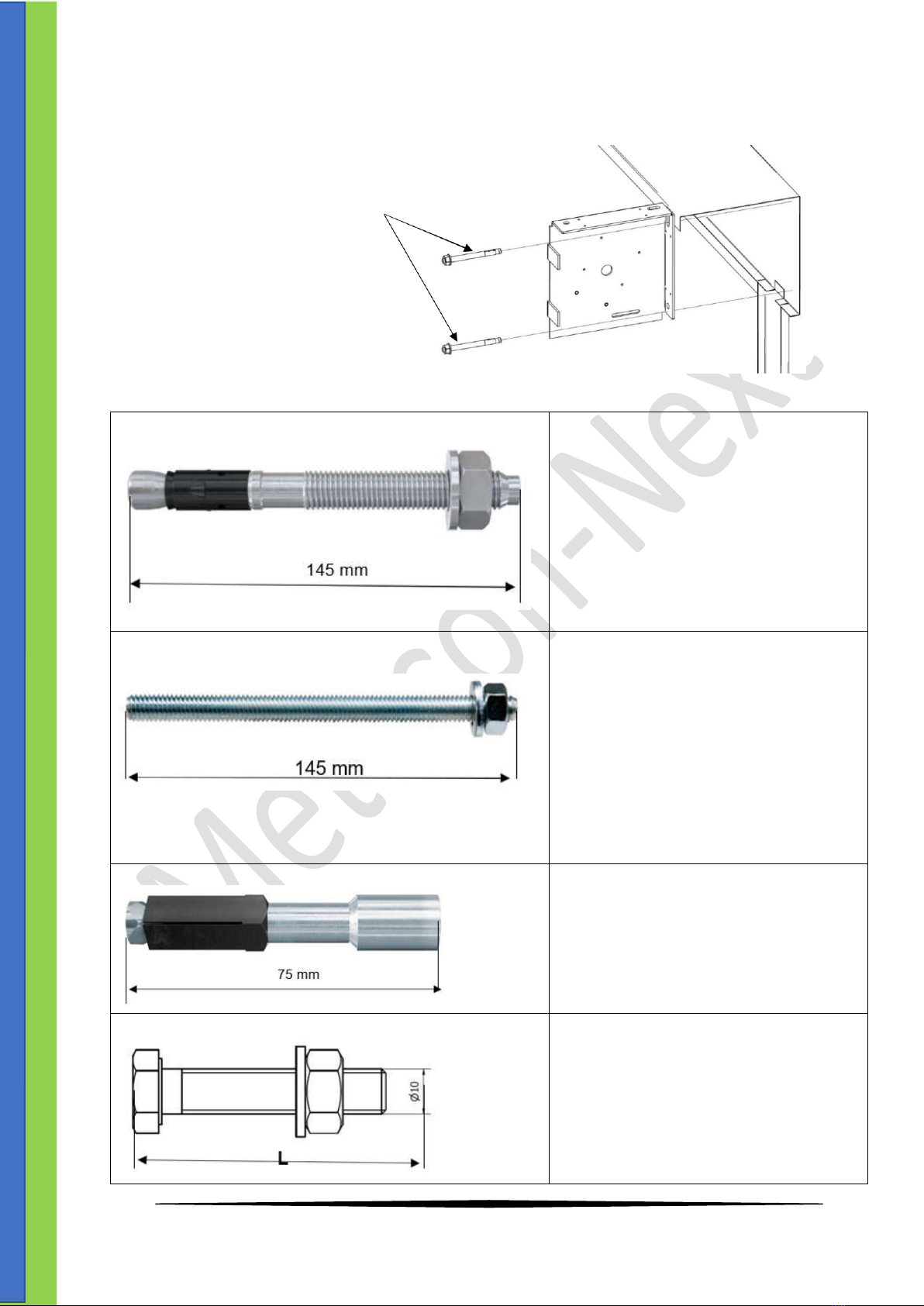
6. Mounting fasteners.
Fasteners required for mounting the supplied fire screen FS EI .
Fischer FAZ II 10/100 bolt anchor
(or equivalent)
6.1 List for mounting of the bracket plates
Fischer FAZ II 10/100 bolt anchor (or equivalent)
R-f or soild concrete
(standard)
Quantity: 4
Anchor drilled hole diameter = 10mm
Min.drilling depth = 100mm
Min. Substrate thickness = 120mm
Chemical anchor (threaded rod) with injection grout
Fischer FIS CS (or equivalent)
Solid masonry walls (concrete blocks,
silicate blocks, or solid bricks) and hollow
masonry walls (hollow blocks, Porotherm
blocks, U-type hollow bricks, and Max
hollow bricks)
Quantity: 4
Anchor drilled hole diameter = 18mm
Min. Drilling depth = 100mm
Min. Substrate thincness = 240mm
Anchor FPX-I (or equivalent)
Cellular concrete block walls (Ytong,
Solbet, Siporex, Suporex, etc.)
Quantity: 4
Anchor drilled hole diameter = 14mm
Min. Drilling depth = 95mm
Min. Substrate thincness = 240mm
Bolts M10
Steel substructure
Quantity: 4
M10 bolth ISO 4017 8.8
M10 nut ISO 4032 8.8
M10 washer ISO 7091
L= length varies whith the steel
substructure thickness

9
Assembly manual FS2 EI60/120 Version 11, jan.. 2021
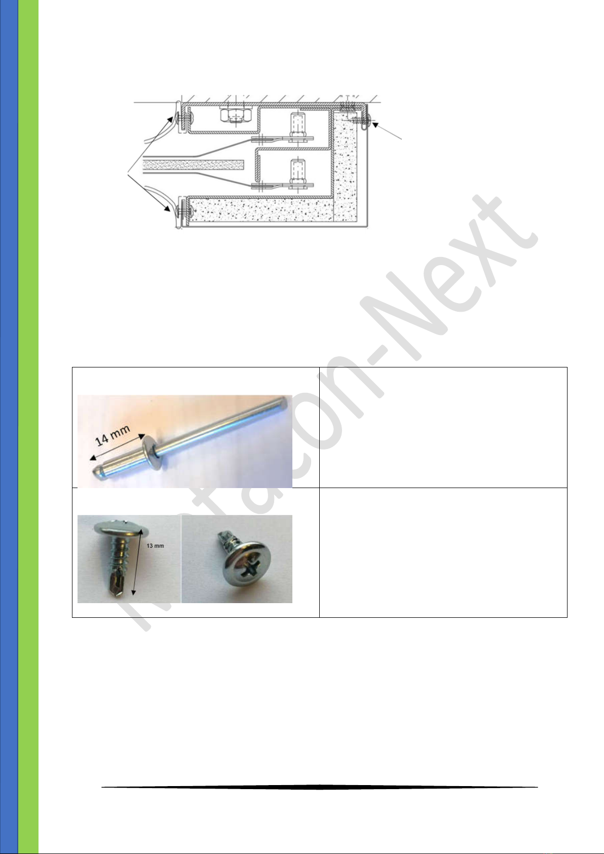
6.2 List of anchoring components for the guide rail wall-mounted installation.
The quantity depends on the height (Ho).
Fischer FAZ II 10/100 bolt anchor
(or equivalent)
Door frame anchor Ø8x92 (or equivalent)
6.3 Installation diagram of the guide rail channel bars.
Fischer FAZ II 10/100 bolt anchor (or equivalent)
R-f or solid concrete walls
Door frame anchor
Quantity: depends on the quantity
depends on the height, one every 500 mm
Fischer FIS CS chemical anchor (threaded rod) with
injection grout (or equivalent)
olid masonry walls (concrete blocks, silicate
blocks, or solid bricks) and hollow
masonry walls (hollow blocks, Porotherm
blocks, and U-type hollow bricks)
Fischer FPX-I anchor (or equivalent)
Cellular concrete block walls (Ytong, Solbet,
Siporex, Suporex, etc.)
Hilti S-MD Ø 6,3 screws (or equivalent)
Steel substructures
In case the wall construction is unspecified by the customer, REINFORCED CONCRETE WALL ANCHORS ARE
PROVIDED ONLY.
10
Assembly manual FS2 EI60/120 Version 11, jan.. 2021
6.4 Other fasteners.
Self drilling screw
Rivet
6.5 . Installation diagram of screws and rivets
Ø 4 x 14mm rivets
For fascia gaskets
Ø 4,2 x 13mm self drilling screw
For installation of the fascias and the Promat fire-
proof panels
11
Assembly manual FS2 EI60/120 Version 11, jan.. 2021
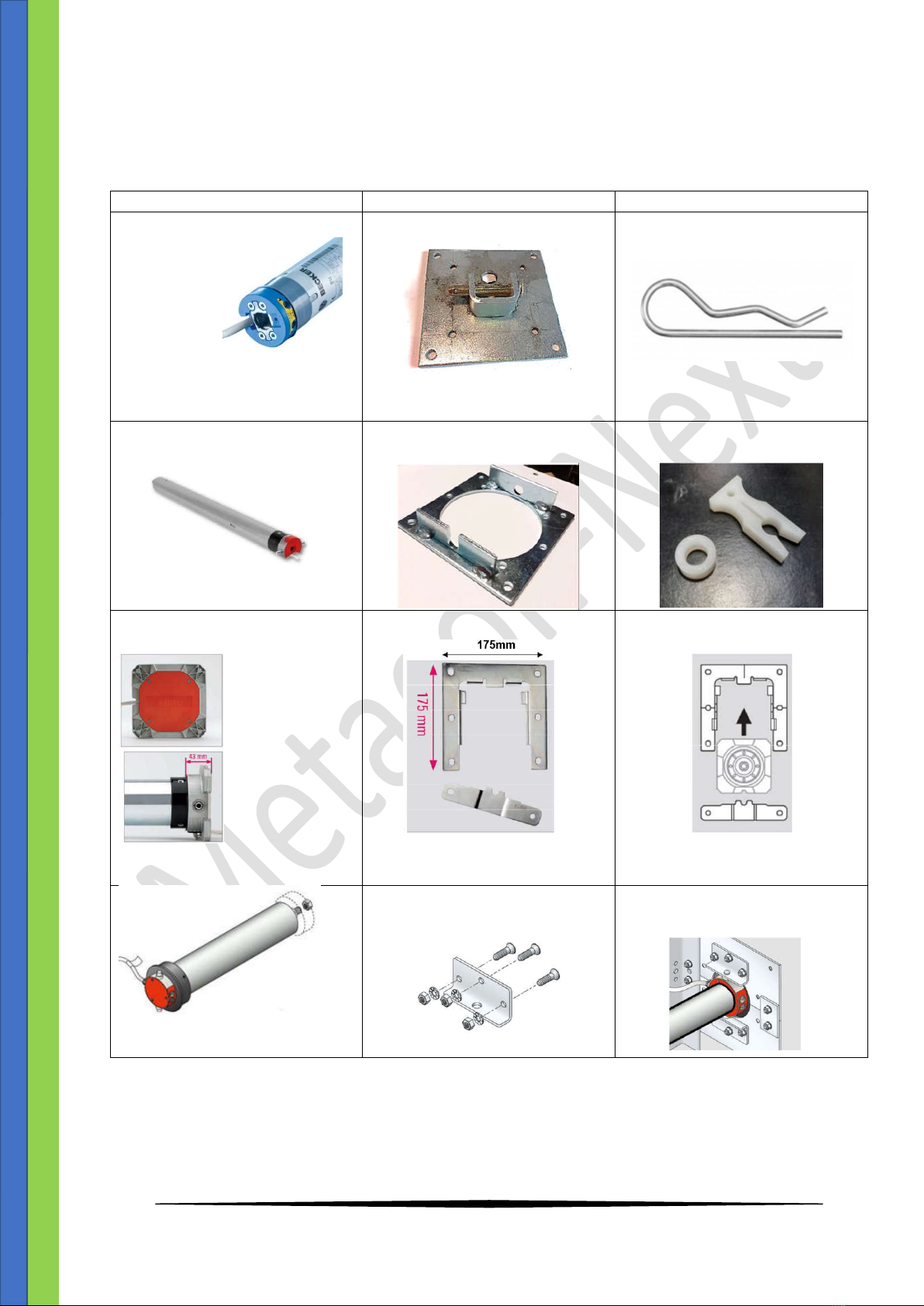
7. List of available motors and brackets with the installation method
Motor
Motor mount
Installation
Becker type;
XL 60
XL 120
Power supply 230V AC
Gravitair closing at interruption
of the 24V DC on the brake
Motor support Becker
Motor split pin for securing
Simu type;
Various type 6
Power supply 230V AC
No Gravitair closing possible
Motor support Simu mounting
with 4 piece M6 bolth
Motor secured by plastic spacer
(ring) and clip
Simu type;
Various type 8S
Power supply 230V AC
No Gravitair closing possible
Motor support wiht 4 piece
M10x30 bolth
Motor support consists of 2 angle
brackets
support mounting with 6 piece
M10 bolth
12
Assembly manual FS2 EI60/120 Version 11, jan.. 2021
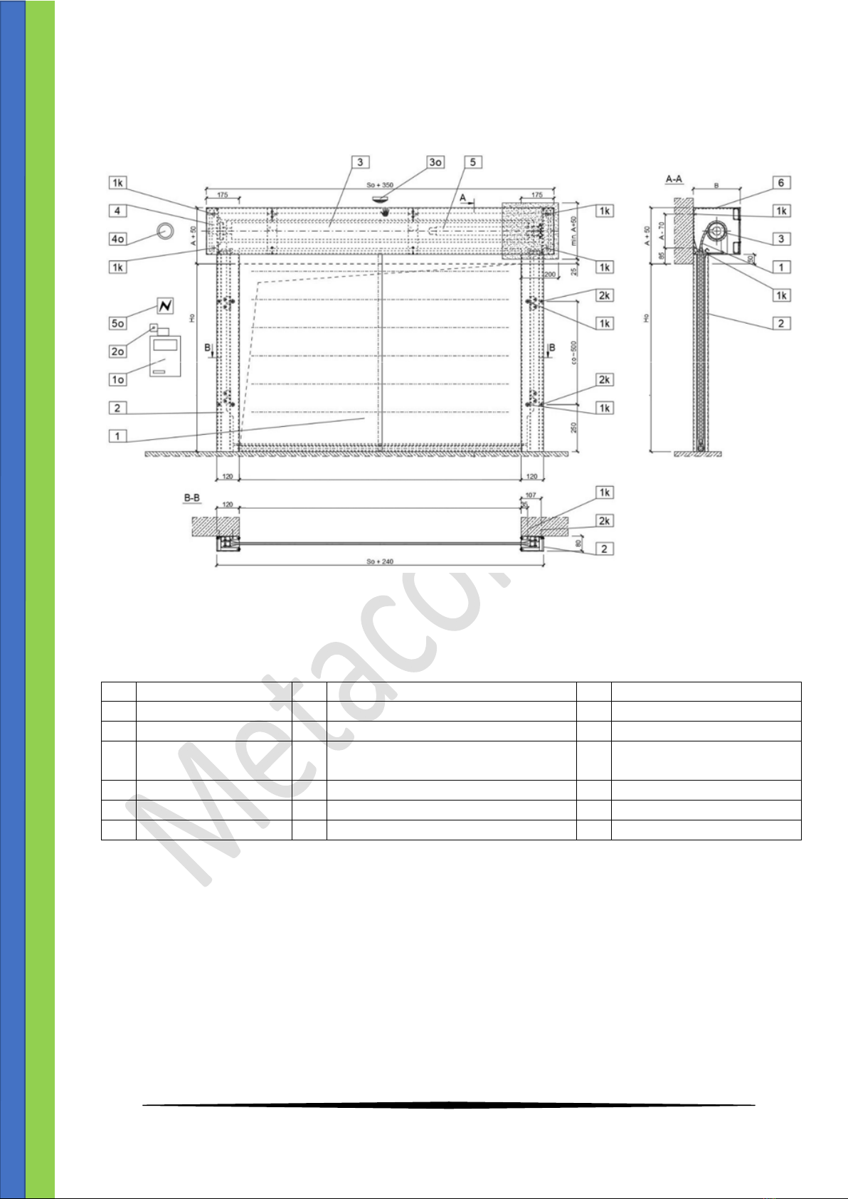
8. Installation from EI60/120 firescreen
Direct wall-mounted installation of firescreen door > 4000mm wide.
Image from direct wall-mounted
Names of the above image
Nr.
Standard part
Nr.
Optional parts
Nr.
Fasteners
1
Curtain
1o
Controlbox MO710AZFNBW.NDS
1k
Anchoring
2
Guide
2o
Key switch
2k
Guide anchoring
3
Aandrijfas
30
Smoke/ Temperature detector
(stand alone)
4
Bearing
4o
Sirene with flash
5
Tubular motor
5o
Power supply fort he controlbox
6
Cover
8.1 Start assembly
- Verify the dimensions of the wall opening and the plane to which the door shaft box will be
installed (level out to the same plane with washers if required)..
- Determine the wall opening centerline. Locate the positions of the guide rail channel bars at distance
of 0.5 x So from the wall opening centerline. Verify that the guide rail goes 50 mm above the bottom
plane of the wall opening header and it is true to the vertical (use a level or a beam plumb laser) .
- Trace out and drill Ø10 mm holes for the bolt anchors. Bolt down the channel bars of the guide rails
without tightening them all the way down to enable horizontal adjustment within the clearance of
the fastening slots.
Clear wall opening width SO/wall opening width S
Clear wall opening width SO/wall opening width S

13
Assembly manual FS2 EI60/120 Version 11, jan.. 2021
Image guide rail
- After mounting the base parts of the guides on the left and right the tubes 60x30mm between the
bracket plate with the M8x25 bolt.
- For EI screen door with bigger then 2500mm be here 3 square tubes are provided
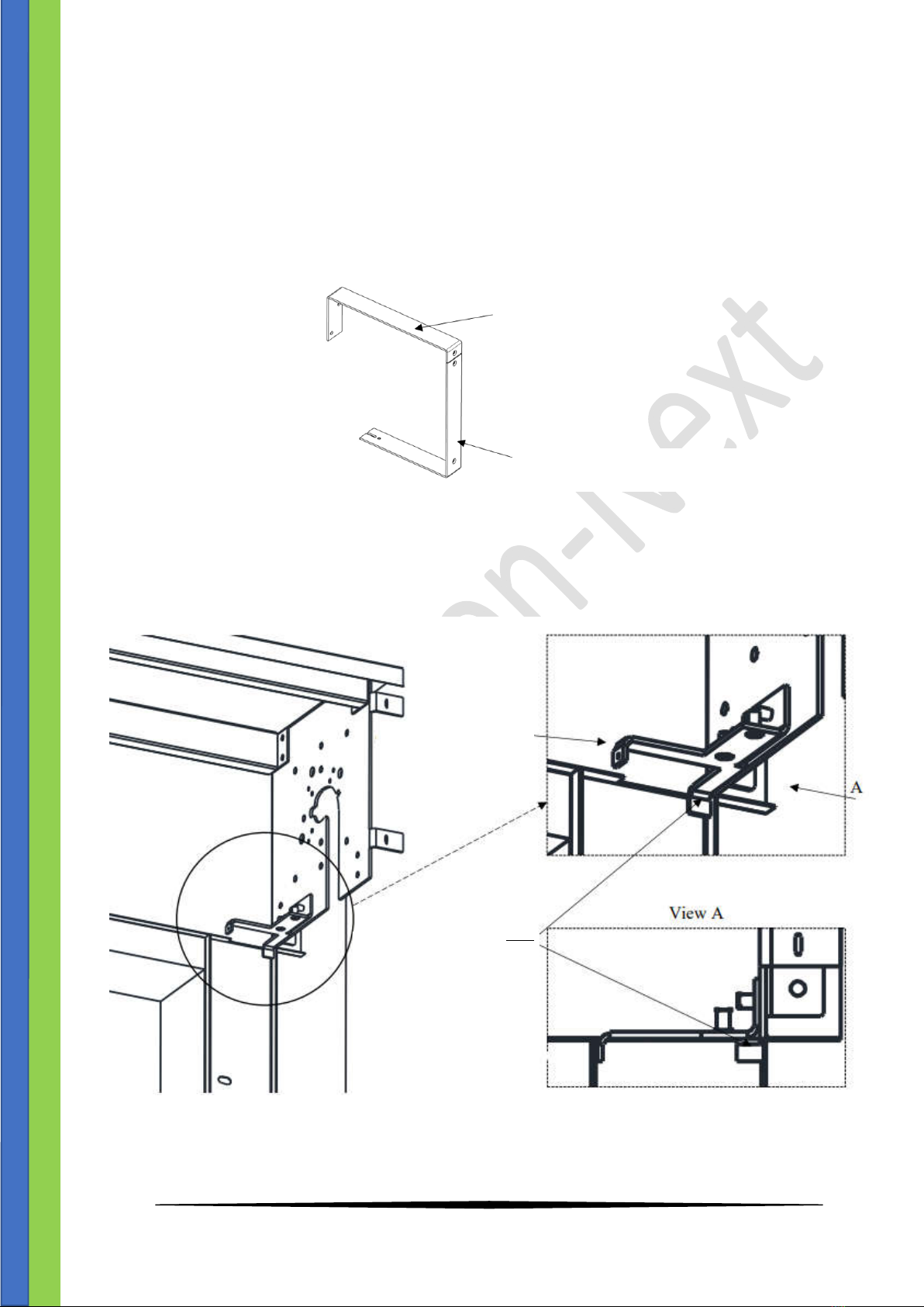
Image fastening of the square tubes with the brackets, angle brace, and top fascia cover
Header line
Wall opening side
Holes and slots fort he
bolth anchors
Door frame anchor holes
Top cover
Middle bracket part A
Bracket
Square tube
Retaining angle brace
14
Assembly manual FS2 EI60/120 Version 11, jan.. 2021
- B Bolt down the retaining angle braces to the brackets with the M6 countersunk bolts. The
angle braces are the reference for the correct orientation of the guide rail channel bars.
With the shaft box brackets and the channel bars installed, the angle braces can be released
temporarily to facilitate access to the winding shaft installation.
- Fasten the middle brackets (part A) and the top fascia cover with rivets to the bolted-down brackets
with the square tubes. If one middle bracket is planned, install it in the centre. If more middle
brackets are planned, install them spaced evenly.
Image middle cover bracket
- Fasten the cover box BA by drilling holes in line with the brackets..
Image guide on corner bracket
Retaining
angle brace
Alignment of the guide
rail channel bars with
the shaft box
components
the retaining angle bar
face touches the guide
rail channel bar ledge
Middle bracket part A
Middle bracket part B
15
Assembly manual FS2 EI60/120 Version 11, jan.. 2021
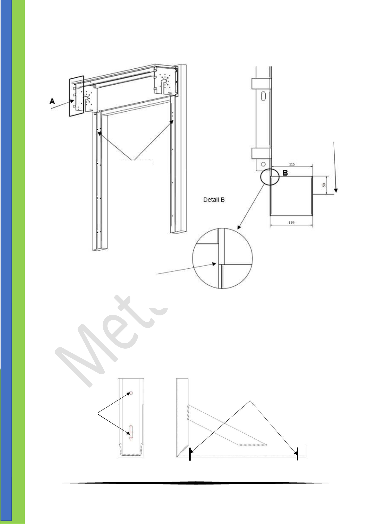
- Check the alignment of the bracket with the guide rail angle brace (detail B) and the level of the top
fascia cover.
- Drill Ø10x160 holes in alignment with the shaft brackets.
- Install the brackets, the top fascia, the middle bracket part A and the square tubes with the anchors.
- For door sizes So > 6000 mm, install the additional shaft box supports in the centre from the top (the
support pieces are custom designs specified for the actual installation conditions and requires no
additional fire-proofing). Install the retaining angle brace with the anchors to the wall and bolt down
with the threaded rods, complete with the shaft box, through the square tubes.
Image installation of the guide rail channel bar and the bracket
Image Middle angle brace
View A
Channel bar 50mm
above the header line
Guide rail
Bracket flush with the
guide rail channel bar
Use the same anchors
as for the installation
of the brackets
Installation locations of the threaded bars which retain
the shaft box to the retaining angle brace.
16
Assembly manual FS2 EI60/120 Version 11, jan.. 2021
- Remove the bearing from the bracket.
- Install the bearing on the non-driven end of the shaft.
- Place the shaft with the wound curtain and the motor in the motor mount bolted to the bracket. With
the motor in the mount, slide the other end of the shaft with the curtain, complete with the bearing,
onto the bracket and bolt the bearing to the bracket with 4 bolts.
.
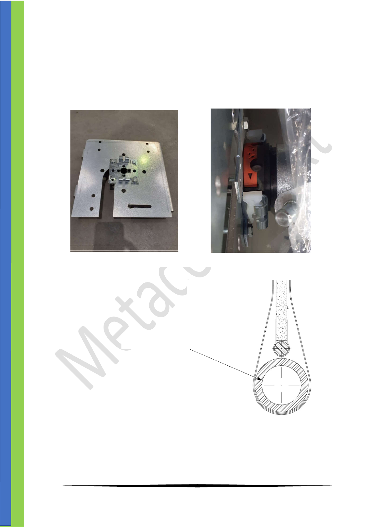
- Check the length of the counterweight
profile (it should be So+25 mm).
- Insert the counterweight profile into the
pocket of the curtain.
Before installing the shaft with the motor
After the installation
Image installation of the motor
Counterweight profile
Image counterweight profile in curtain

17
Assembly manual FS2 EI60/120 Version 11, jan.. 2021
- Connect the motor to the MO710 controlbox on wire 4 and 5
on the 24V DC and the wires 1,2 and 3 on the adjusting cable.
Send the screen down gently, if necessary accompany the first
time. Adjust the motor down and up with the two adjusting
screws on the motor. Pay attention to the direction of rotation
of the shaft. See also the manual of the engine supplier.
8.2 Installation of the curtain descent mechanical (angle bar).
CAUTION! This Section applies to curtain doors with gravity descent.
- With the shaft installed, run the drive motor in the curtain closing direction.
- With the curtain unwound down to the floor surface, mark out the curtain descent mechanical stop
(30x30 wide angle bar). Next, turn the shaft to rivet / secure the angle bar
(with 4x13 rivets or 4x25 self-drilling screws, depending on the curtain door size).
- When drilling with the tubular motor, make sure you do not drill too deep and damage the motor.
-
Image adjusting cable motor
Marked out angle
barinstallation location
Shaft shown turned
inposition for securing the
angle bar
Image Installation of the curtain descent mechanical (angle bar)
18
Assembly manual FS2 EI60/120 Version 11, jan.. 2021
- Install the third 60 mm x 30 mm square tube.
- Use the 4.2 x 19 mm countersunk self-drilling screws to secure the middle bracket part B to
the square tube.
9. Mounting curtain guide.
- Installation of the retaining profile between the bracket plates and adjust them against the canvas.
Image installation of the middle bracket
Middle bracket part A
Middle bract part B
60x30 mm square tube
4,2x19 mm self drilling screws
Image Installation of the retaining profile
Retaining profile

19
Assembly manual FS2 EI60/120 Version 11, jan.. 2021
10. Mounting guide.
- Wind the curtain onto the shaft inside of the shaft box.
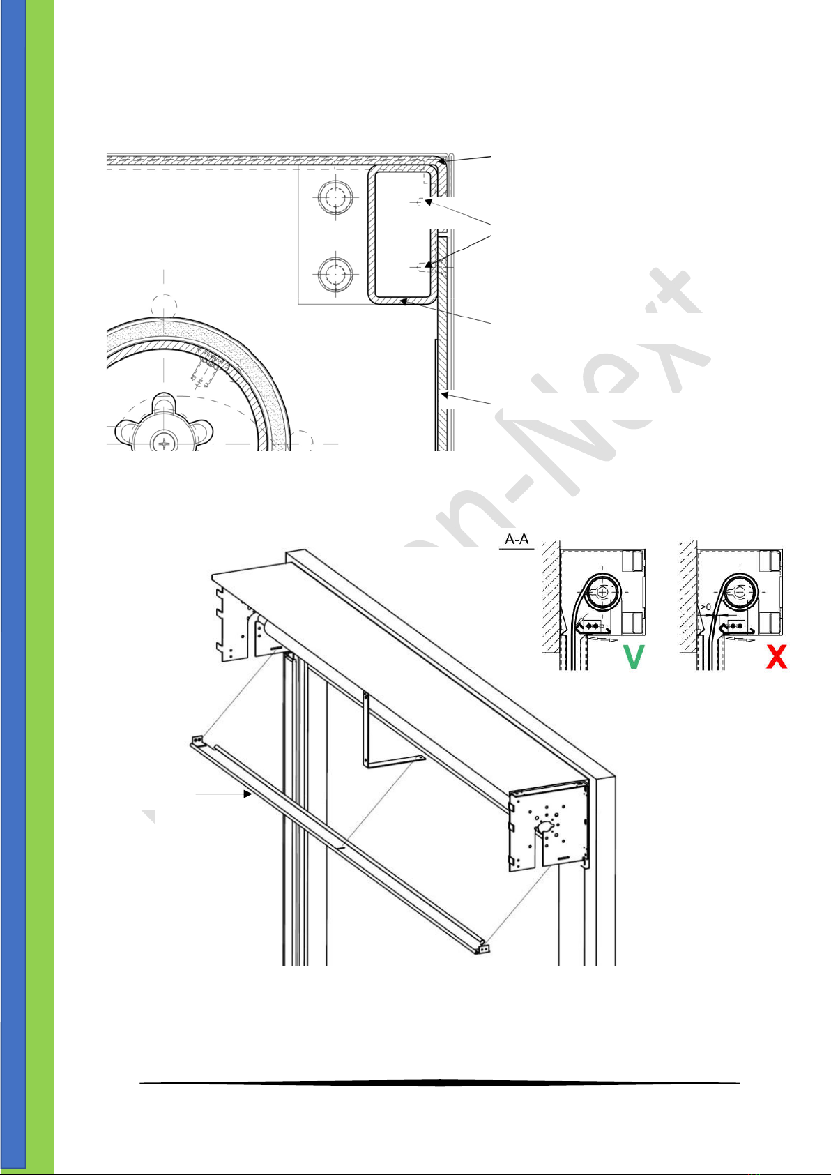
- Use the channel bar holes to drill Ø8 holes for the door frame anchors ( see image below).
Installation location of the
door frame anchor Ø 8mm
2 mm of play between the fascia and the guide rail internal parts.
Image installation of the guide rails
Image guide rail parts
1.
Fascia complete with
Promat fire-proof panels.
2. . Outer guide rail run-in
plate.
3. Wall-side guide rail run-in
plate.
4. Guide rail channel bar.

20
Assembly manual FS2 EI60/120 Version 11, jan.. 2021
- With the guide rail internal parts installed, install the Promat fire-proof panels and the outer fascia (1)
(Image guide rail parts) with the 4.2x13 mm self-drilling screws.
- - Now place the fire resistant cloth in the recesses of the guide rails so that the cloth guides are on the
sides of the guide in their separate guide openings, see also the image below.
- Instal the front and side covers.
Running shoe curtain
2 mm
curtain
Fascia gasket
Image Cross-sectional view of the guide rail engaged by the curtain
This manual suits for next models
1
Table of contents
Other Metacon-Next Safety Equipment manuals


Popular Safety Equipment manuals by other brands

CSE
CSE BIOMARINE PROIWT user manual

Seago
Seago LIFEBUOY owner's manual

HACA LEITERN
HACA LEITERN 0529.1904 Instructions for assembly and use

CMC
CMC PROSWIVEL instruction manual

CarlStahl
CarlStahl Textile Bridle Sling operating instructions

Classic Accessories
Classic Accessories Over Drive 5th Wheel Hitch Cover instructions


