Reer ARGOLUX AS Series User manual

TABLE OF CONTENTS
TABLE OF CONTENTSTABLE OF CONTENTS
TABLE OF CONTENTS
GENERAL OBSERVATIONS pag. 2
22
2
APPLICATIONS pag. 2
22
2
DESIGN AND OPERATION pag. 3
33
3
TEST SEQUENCE AND CONTROLS pag. 7
77
7
CONTACTS STATUS pag. 8
88
8
LED STATUS INDICATORS pag. 9
99
9
TECHNICAL FEATURES pag. 10
1010
10
DIMENSIONS pag. 12
1212
12
INSTALLATION pag. 15
1515
15
POSITIONING AND SAFETY DISTANCES pag. 17
1717
17
GROUPING OF SEVERAL SETS pag. 21
2121
21
REFLECTING SURFACES pag. 22
2222
22
DEFLECTION MIRRORS pag. 24
2424
24
ELECTRICAL CONNECTION pag. 25
2525
25
MOUNTING AND OPTICAL ALIGNMENT pag. 28
2828
28
INSPECTION AND MAINTENANCE pag. 29
2929
29
TROUBLE SHOOTING pag. 30
3030
30
ORDERING CODE, ACCESSORIES AND SPARE PARTS pag. 32
3232
32
WARRANTY pag. 34
3434
34
PHOTOELECTRIC
SAFETY
BARRIERS
ARGOLUX
AS SERIES
INSTALLATION AND
MAINTENANCE
MANUAL


GENERAL OBSERVATIONS
The ARGOLUX AS curtain is a multibeam optoelectronic protective device
designed to secure operators working on dangerous machines in an
industrial environment.
The ARGOLUX AS system is made up of an emitter, a receiver and a
separatecontrolunit.The3unitsarecombinedtoprovideatype2fail-safe
system as defined by the EN 61496-1 and prEN 61496-2 («Safety of
machinery - Electro-sensitive protective system»).
When an opaque object (such as the operator’s hand or arm) enters the
dangerous areas and therefore goes through the detection field between
the emitter and the receiver, the control unit de-energizes its output relays.
The result is the immediate stoppage of the dangerous movement if the
control unit is correctly connectedto the machine control circuitry.
To fulfil correctly its safety function, the safety system must be correctly
interfaced to the machine circuitry and correctly positioned regarding the
danger zone to reduce or cancel risk.
APPLICATIONS
APPLICATIONSAPPLICATIONS
APPLICATIONS
The ARGOLUX AS curtain may be used on industrial machines for which
the risk assessment allows the use of a type 2 electrosensitive protective
system.
The detection of anobject obscuring anybeamin the curtainde-energizes
theoutputcircuitofthecurtainandthemovingbodyofthemachinecomes
to rest.
2
22
2

The following are examples of machines where the ARGOLUX AS may be
used:
•Machinery for product handling such as conveyors, palletizing,
collating machines;
•Packaging and wrapping devices;
•Automated assembly lines;
•Automated warehousing.
To control access all around a machine, the ARGOLUX AS curtain can be
usedwithdeflectionmirrorstobuildaperimetricprotectionsurroundingthe
dangerous area.
For applications in the food and beverage industry consult the factory to
checkthe compliance with thematerials and chemical agents involved.
The safeguarding function of optoelectronic protective devices is not
efficient if:
The moving body of the machine cannot be electrically con
The moving body of the machine cannot be electrically conThe moving body of the machine cannot be electrically con
The moving body of the machine cannot be electrically con-
--
-
trolled and if its movement cannot be stopped at any time
trolled and if its movement cannot be stopped at any timetrolled and if its movement cannot be stopped at any time
trolled and if its movement cannot be stopped at any time
during the machine cycle.
during the machine cycle.during the machine cycle.
during the machine cycle.
Danger is related to falling objects or object ejection.
Danger is related to falling objects or object ejection.Danger is related to falling objects or object ejection.
Danger is related to falling objects or object ejection.
If necessary, in the case of technical safety questions, consult the safety
authorities of your country or the competent industry association.
DESIGN AND OPERATION
DESIGN AND OPERATIONDESIGN AND OPERATION
DESIGN AND OPERATION
Sensing function.
Sensing function.Sensing function.
Sensing function.
Theemitterismadeupofarowofinfraredlightemittingdiodesandlenses.
Each diode successively emits an infrared beam with a scanning frequency
of about 15kHz.
The receiver sensors catch the beams and an invisible protection field is
created between the emitter and the receiver units.
!
!
3
33
3

The synchronisation between the emitting diodes and the receiver sensors
isprovidedbyanextrabeamemittedbythereceiverunittowardstheemitter
unit.Thissynchronisationbeamdelimitsonesideofthedetectionzone(see
figure 1).
When an opaque object with a diameter greater or equal to the resolution
ofthesysteminterruptsoneorseveralbeams(figure2),thereceiveroutput
provides an alarm signal to command the control unit to de-energize the
output relays.
The resolution corresponds to the size of the smallest object
The resolution corresponds to the size of the smallest objectThe resolution corresponds to the size of the smallest object
The resolution corresponds to the size of the smallest object
that can be detected within the protection zone, obscuring at
that can be detected within the protection zone, obscuring atthat can be detected within the protection zone, obscuring at
that can be detected within the protection zone, obscuring at
least one beam (figure
least one beam (figureleast one beam (figure
least one beam (figure 2).
2).2).
2).
The resolution is always the same in the protection zone, whatever the
scanning range may be since it only depends on the lens diameter and the
lens pitch.
!
Fig. 1
Fig. 1Fig. 1
Fig. 1
The synchronisation beam is part of the detection zone.
The synchronisation beam is part of the detection zone.The synchronisation beam is part of the detection zone.
The synchronisation beam is part of the detection zone.
Fig. 2
Fig. 2Fig. 2
Fig. 2
An object with a diameter equal or greater than the resolution R
An object with a diameter equal or greater than the resolution RAn object with a diameter equal or greater than the resolution R
An object with a diameter equal or greater than the resolution R
interrupts at least one beam.
interrupts at least one beam.interrupts at least one beam.
interrupts at least one beam.
P = Lens pitch;
P = Lens pitch;P = Lens pitch;
P = Lens pitch;
D = Lens diameter;
D = Lens diameter;D = Lens diameter;
D = Lens diameter;
R = Resolution = P+D
R = Resolution = P+DR = Resolution = P+D
R = Resolution = P+D
4
44
4

The presence in the protection zone (figure
The presence in the protection zone (figureThe presence in the protection zone (figure
The presence in the protection zone (figure 3) of an object
3) of an object3) of an object
3) of an object
greater or equal to the resolution of the curtain de-energizes
greater or equal to the resolution of the curtain de-energizesgreater or equal to the resolution of the curtain de-energizes
greater or equal to the resolution of the curtain de-energizes
the output relays.
the output relays.the output relays.
the output relays.
Two different resolutions are available (ø35mm or ø55mm) and the
following table shows the values of the detection and protection heights.
Fig. 3
Fig. 3Fig. 3
Fig. 3
Position and dimensions of the detection zone and the protection zone.
Position and dimensions of the detection zone and the protection zone.Position and dimensions of the detection zone and the protection zone.
Position and dimensions of the detection zone and the protection zone.
!
MODELS
MODELSMODELS
MODELS DETECTION ZONE
DETECTION ZONEDETECTION ZONE
DETECTION ZONE
HEIGHT
HEIGHTHEIGHT
HEIGHT PROTECTION ZONE
PROTECTION ZONEPROTECTION ZONE
PROTECTION ZONE
HEIGHT
HEIGHTHEIGHT
HEIGHT C
CC
CR
RR
R
AS 203 185 230 65 35
AS 405 355 440 45 55
AS 403 400 65 35
AS 605 525 610 45 55
AS 603 570 65 35
AS 705 700 785 45 55
AS 703 745 65 35
AS 905 870 955 45 55
AS 903 915 65 35
AS 1105 1045 1130 45 55
AS 1103 1090 65 35
AS 1205 1215 1300 45 55
AS 1203 1260 65 35
AS 1405 1390 1475 45 55
AS 1403 1435 65 35
AS 1605 1560 1645 45 55
AS 1603 1605 65 35
Dimensions in mm
5
55
5

Argolux ASlight curtainis available alsoin theMULTIBEAM configuration.
Fromtheopticalpointofview,abeam’spitchof172mmisthecharacteristic
of these seven models.
Duetotheparticular configuration ofthebeams (figure
Duetotheparticular configuration ofthebeams (figureDuetotheparticular configuration ofthebeams (figure
Duetotheparticular configuration of thebeams(figure 4)the
4) the4) the
4) the
Argolux AS MULTIBEAM models shall be used only to detect
Argolux AS MULTIBEAM models shall be used only to detectArgolux AS MULTIBEAM models shall be used only to detect
Argolux AS MULTIBEAM models shall be used only to detect
intrusion of the whole body of a person and not parts of the
intrusion of the whole body of a person and not parts of theintrusion of the whole body of a person and not parts of the
intrusion of the whole body of a person and not parts of the
body (hands, legs, ...).
body (hands, legs, ...).body (hands, legs, ...).
body (hands, legs, ...).
See the following tablefor the MULTIBEAM optic characteristics.
!
Fig. 4
Fig. 4Fig. 4
Fig. 4
MULTIBEAM Models: beams configuration.
MULTIBEAM Models: beams configuration.MULTIBEAM Models: beams configuration.
MULTIBEAM Models: beams configuration.
Model
ModelModel
Model AS
ASAS
AS 418
418418
418 618
618618
618 718
718718
718 918
918918
918 1118
11181118
1118 1218
12181218
1218 1418
14181418
1418 1618
16181618
1618
Numberofbeams 345678910
Lens pitch mm 172
6
66
6

TEST SEQUENCE AND CONTROLS
TEST SEQUENCE AND CONTROLSTEST SEQUENCE AND CONTROLS
TEST SEQUENCE AND CONTROLS
Optical scanning circuitry.
Optical scanning circuitry.Optical scanning circuitry.
Optical scanning circuitry.
The scanning circuitry of ARGOLUX AS safety barrier is based upon a
self-checking principle which permanently controls its correct operation.
Particularly,thesystemcontrolsthemultiplexsignalontheemitterside,and
measures theIR light pulse period emitted foreach beam of the curtain.
The reversed operations are carried out on the receiver side where the
system controls the demultiplex signals and recognize the infrared light
pulse thanks to the measurement of the caught light period.
An accurate synchronisation enables this identification and avoids taking
into account possible infrared disturbances.
If an unwanted condition occurs during the IR light beam transmission (an
object is in the detection field or a failure appears), the receiver sends a
command signal to the control unit which de-energizes its relays and
remains in the alarm condition until the fault condition is removed.
Output circuitry.
Output circuitry.Output circuitry.
Output circuitry.
The control unit AU S3 controls the correct operation of the both emitter
and the receiver units thanks to its electrical connection with the receiver
ASR. The receiver provides thecontrol unitwith a signal through its unique
relay output. As mentioned in the EN 61496-1 norm, the test facility
provided with type 2 optoelectronic protective devices is partly designed to
checkthe correct operation ofthis relayoutput.
Other operations are checked during the test to ensure the integrity of the
system:
•The correct interlinking of the test sequence and the effective reset
of the system (test command);
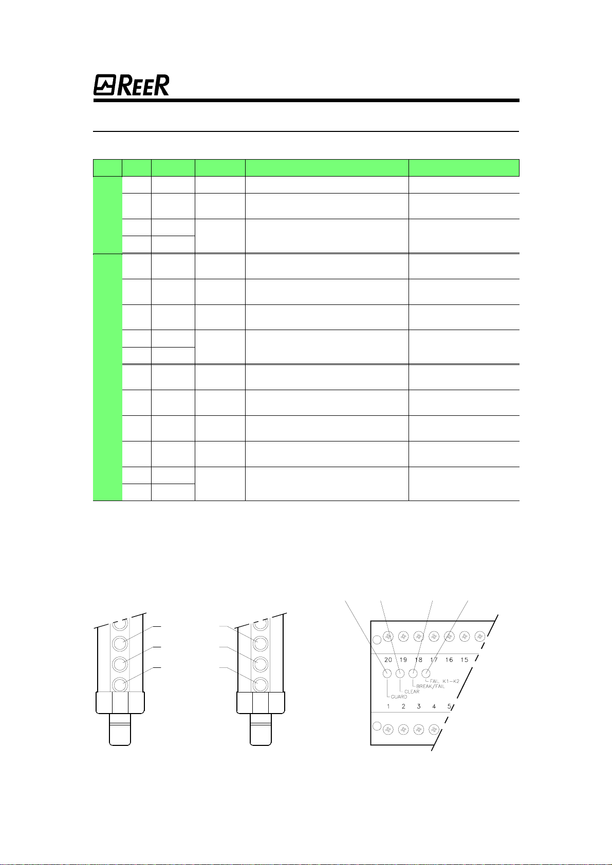
•The reaction time of the two inner relays A and B (safety relays with
guided contacts) and the reaction time of the two external relays
K1 and K2, if auxiliary contacts of K1 and K2 are connected to
terminals 5 and 6 (use only safety relays with guided contacts);
•The inner command of A and B relays. A possible failure of one
component of the output circuitry can only be detected during the
test phase, and therefore the control unit de-energizes its relays
only when the next test is applied. This is also true for external
relays K1 and K2 by means of the feedback control (see below).
Test input.
Test input.Test input.
Test input.
The ARGOLUX AS curtain is a type 2 opto-electronic protective device
designed according to the EN 61496-1 and prEN 61496-2 European
Norm.Its safeguardingfunction isbasedupon aperiodicperformancetest
initiated by the machine.
7
77
7

The control unit displays a test input whichmust be used to generate a test
sequence before each reset of the safety system or before a machine cycle
if necessary.
European regulations enforce the test performance before the effective
reset of the system, at power up and after any intrusion into the detection
field.
The test command is activated by closing a contact between terminals 15
and 16 during 10ms at least. The test is then performed during 100ms.
Ifafailureis detected,theresetofthesystemis impossibleandnomachine
cycle can be initiated. If no a failure is detected, the control unit energizes
its relays A and B, which is the condition to initiate a new machine cycle.
Itispossibletogenerateatestsequenceatanymomentbyclosingacontact
between terminals 15 and 16.
The first step consists in controlling the correct operation of the scanning
circuitry.
The system checks that the ASR receiver output relay goes to the OFF state
whenthedetectionfieldisbroken.Thisdetectioniselectronicallysimulated.
Then, the next step consists in controlling the AU S3 output relay . The ON
and OFF reactiontimes of both relays are measured and compared.
During the100ms testperiod, the outputs remainopen(contactsbetween
terminals 8-13and 9-12 remain open).
The test sequence can be generated at power up, after any
The test sequence can be generated at power up, after anyThe test sequence can be generated at power up, after any
The test sequence can be generated at power up, after any
intrusion into the detection field and at any other moment if
intrusion into the detection field and at any other moment ifintrusion into the detection field and at any other moment if
intrusion into the detection field and at any other moment if
the detection field is clear.
the detection field is clear.the detection field is clear.
the detection field is clear.
The test is only allowed when the detection field is clear.
The test is only allowed when the detection field is clear.The test is only allowed when the detection field is clear.
The test is only allowed when the detection field is clear.
CONTACTS STATUS
CONTACTS STATUSCONTACTS STATUS
CONTACTS STATUS (Ref.: connection diagram page 27)
!
!
Control unit status
GUARD CLEAR BREAK FAIL FAIL (FAIL K1-K2)
Output of the
the receiver ASR
Sensing field
not interrupted Sensing field
interrupted Sensing field
not interrupted Sensing field
interrupted
Output of
the control
unit AU S3
8-13
9-12
10-11
Relay
K1 K1-1
K1-2
Relay
K2 K2-1
K2-2
8
88
8

LED STATUS INDICATORS
LED STATUS INDICATORSLED STATUS INDICATORS
LED STATUS INDICATORS
EMITTER
Fig. 5
Fig. 5Fig. 5
Fig. 5
Led status indicators on emitter and receiver.
Led status indicators on emitter and receiver.Led status indicators on emitter and receiver.
Led status indicators on emitter and receiver. Fig. 6
Fig. 6Fig. 6
Fig. 6
Led status indicators on control unit.
Led status indicators on control unit.Led status indicators on control unit.
Led status indicators on control unit.
7RECEIVER 8 9 10
1
2
3
4
5
6
UNIT
UNITUNIT
UNIT LED N°
LED N°LED N°
LED N° COLOUR
COLOURCOLOUR
COLOUR STATE
STATESTATE
STATE INDICATIONS
INDICATIONSINDICATIONS
INDICATIONS AU S3 STATUS
AU S3 STATUSAU S3 STATUS
AU S3 STATUS
1 Green On Reception of the synchronisation beam GUARD - CLEAR - BREAK (*)
2Yellow On Misalignment of the
synchronisation beam BREAK (*)
2Yellow
Alternately
flickering Failure on the emitter unit BREAK (*)
3Red
4 Green On Protection field is clear,
output relay of AU S3 are energized GUARD (*)
5Yellow On Protection field is clear,
output relay of AU S3 are de-energized CLEAR (*)
6Red On Protection field is entered,
output relay of AU S3 are de-energized BREAK (*)
5Yellow
Alternately
flickering Failure on the receiver unit BREAK (*)
6Red
7 Green On Protection field is clear,
output relay of AU S3 are energized GUARD
8Yellow On Protection field is clear,
output relay of AU S3 are de-energized CLEAR
9Red On Protection field is entered,
output relay of AU S3 are de-energized BREAK
9RedFlickering Failure on the control unit
output relay of AU S3 are de-energized FAIL
9Red
Flickering Failure on the external relays K1 and K2
output relay of AU S3 are de-energized FAIL
(FAIL K1-K2)
10 Red
(*) With control unit AU S3 correctly operating.
RECEIVER
ASR
CONTROL UNIT
AU S3 EMITTER
ASE
9
99
9

TECHNICAL FEATURES
Emitter and receiver with a ø35mm resolution.
Emitter and receiver with a ø35mm resolution.Emitter and receiver with a ø35mm resolution.
Emitter and receiver with a ø35mm resolution.
Emitter and receiver with a ø55mm resolution.
Emitter and receiver with a ø55mm resolution.Emitter and receiver with a ø55mm resolution.
Emitter and receiver with a ø55mm resolution.
Model
ModelModel
Model AS
ASAS
AS 203
203203
203 403
403403
403 603
603603
603 703
703703
703 903
903903
903 1103
11031103
1103 1203
12031203
1203 1403
14031403
1403 1603
16031603
1603
Protection heights mm 230 400 570 745 915 1090 1260 1435 1605
Number of beams 9 17 25 33 41 49 57 65 73
Resolution mm 35
Lens pitch mm 21,5
Lens diameter mm 12
Scanning range m 0 ÷12
Ambient light immunity lx > 50.000
Response time ms 13 14 15 16 17
Power supply Vdc 24 ± 20%
Power consump-
tion
at 24Vdc
Emitter W4,2
Receiver 3,3 4,6 6 7,4 8,8 10,1 11,5 12,9 14,3
Operating temperature °C 0 ÷55 (without condensation and ice)
Sealing IP 65
Width mm 50
Dimensions Depth 70
Height 360 530 705 875 1050 1220 1395 1565 1735
Model
ModelModel
Model AS
ASAS
AS 405
405405
405 605
605605
605 705
705705
705 905
905905
905 1105
11051105
1105 1205
12051205
1205 1405
14051405
1405 1605
16051605
1605
Protection heights mm 440 610 785 955 1130 1300 1475 1645
Number of beams 9 13 17 21 25 29 33 37
Resolution mm 55
Lens pitch mm 43
Lens diameter mm 12
Scanning range m 0 ÷12
Ambient light immunity lx > 50.000
Response time ms 13 14 15
Power supply Vdc 24 ± 20%
Power consump-
tion
at 24Vdc
Emitter W4,2
Receiver 3,3 4 4,6 5,3 6 6,7 7,4 8,3
Operating temperature °C 0 ÷55 (without condensation and ice)
Sealing IP 65
Width mm 50
Dimensions Depth 70
Height 530 705 875 1050 1220 1395 1565 1735
10
1010
10

Emitter and receiver: MULTIBEAM models.
Emitter and receiver: MULTIBEAM models.Emitter and receiver: MULTIBEAM models.
Emitter and receiver: MULTIBEAM models.
Control unit AU S3.
Control unit AU S3.Control unit AU S3.
Control unit AU S3.
Power supply Vdc 24 ±20%
Power consumption W 5,5
Output relays (*) 2 N.O. contacts 2A 125Vac
1 N.C. contact 2A 125Vac
Response time ms ≤15
Min. closing time
of the test contact ms 10
Test duration ms 100
Electrical connections Terminal blocks
Cable lenght (**) m 100 max
Operating temperature °C 0 ÷ 55
Sealing
(housing) IP 40
Sealing
(terminal blocks) IP 2X
Mechanical mounting Quick mounting on Omega rail according to EN 50022-35
Dimensions mm 100 x 73 x 120
Weight g 500
(*) Refer to “Load features” in the Electrical connection chapter (page 26).
(**) We recommend shielded cable where the level of electrical disturbances is higher than the specified
IEC 801-4/level IV.
Model
ModelModel
Model AS
ASAS
AS 418
418418
418 618
618618
618 718
718718
718 918
918918
918 1118
11181118
1118 1218
12181218
1218 1418
14181418
1418 1618
16181618
1618
Numberofbeams 345678910
Lens pitch mm 172
Lens diameter mm 12
Scanning range m 0 ÷12
Ambient light immunity lx > 50.000
Response time ms 13 14 15
Power supply Vdc 24 ± 20%
Power consump-
tion
at 24Vdc
Emitter W4,2
Receiver 3 max.
Operating temperature °C 0 ÷55 (without condensation and ice)
Sealing IP 65
Width mm 50
Dimensions Depth 70
Height 530 705 875 1050 1220 1395 1565 1735
11
1111
11

DIMENSIONS (in mm)
Emitters ASE and receivers ASR.
Emitters ASE and receivers ASR.Emitters ASE and receivers ASR.
Emitters ASE and receivers ASR.
Model
ModelModel
Model
AS
ASAS
AS 203
203203
203 403
403403
403
405
405405
405
418
418418
418
603
603603
603
605
605605
605
618
618618
618
703
703703
703
705
705705
705
718
718718
718
903
903903
903
905
905905
905
918
918918
918
1103*
1103*1103*
1103*
1105*
1105*1105*
1105*
1118*
1118*1118*
1118*
1203*
1203*1203*
1203*
1205*
1205*1205*
1205*
1218*
1218*1218*
1218*
1403*
1403*1403*
1403*
1405*
1405*1405*
1405*
1418*
1418*1418*
1418*
1603*
1603*1603*
1603*
1605*
1605*1605*
1605*
1618*
1618*1618*
1618*
A 250 425 595 770 940 1115 1285 1455 1630
B 305 475 650 820 995 1165 1340 1510 1680
Mounting 2 LL brackets with 2 mounting pins 2 LH brackets with 4 mounting pins
(*) When the emitter and the receiver are exposed to hight vibrations, it is recommended to use the antivibration dampers
(see page 29).
12
1212
12

LL and LH brackets.
LL and LH brackets.LL and LH brackets.
LL and LH brackets.
Mounting pin and connectors.
Mounting pin and connectors.Mounting pin and connectors.
Mounting pin and connectors.
Control unit AU S3.
Control unit AU S3.Control unit AU S3.
Control unit AU S3.
13
1313
13

Deflection mirrors.
Deflection mirrors.Deflection mirrors.
Deflection mirrors.
Brackets for mirrors.
Brackets for mirrors.Brackets for mirrors.
Brackets for mirrors.
Model
ModelModel
Model H
HH
H
SP 200S 370
SP 400S 540
SP 600S 715
SP 700S 885
SP 900S 1060
SP 1100S 1230
SP 1200S 1400
SP 1400S 1575
SP 1600S 1750
14
1414
14

INSTALLATION
ReferringtotheEN61496-1Europeannorm,apossiblefailureofatype
2 optoelectronic protective device is detected when the next test is
applied.
Therefore, the following must be checked before installing the ARGOLUX
AS series barrier:
the risk assessment for the considered machine allows the
the risk assessment for the considered machine allows thethe risk assessment for the considered machine allows the
the risk assessment for the considered machine allows the
use of a type 2 optoelectronic protective device.
use of a type 2 optoelectronic protective device.use of a type 2 optoelectronic protective device.
use of a type 2 optoelectronic protective device.
Foratype2 protectivedevice,thetestsequencemustbegeneratedbefore
any new energising of the output relays. Output relays are energized if no
failure is detected during the test sequence.
Before installing the ARGOLUX AS series barrier, make sure that:
the machine or the working cycle is adapted to the mode of
the machine or the working cycle is adapted to the mode ofthe machine or the working cycle is adapted to the mode of
the machine or the working cycle is adapted to the mode of
operation of a type 2 protective device.
operation of a type 2 protective device.operation of a type 2 protective device.
operation of a type 2 protective device.
The working cycleof the machineor any dangerous movementmust be set
in motion using a specific command device such as a pushbutton.
Therefore:
the ARGOLUX AS safety barrier must be used as a protective
the ARGOLUX AS safety barrier must be used as a protectivethe ARGOLUX AS safety barrier must be used as a protective
the ARGOLUX AS safety barrier must be used as a protective
device thatoutputs stop signalsand not asa command device
device thatoutputs stop signalsand not asa command devicedevicethatoutputs stop signalsand notasa command device
device thatoutputs stop signalsand not asa command device
that outputs control signals.
that outputs control signals.that outputs control signals.
that outputs control signals.
When the test needs to be generated by the operator himself using a
pushbutton, the following applies:
•The pushbutton should be fixed outside the dangerous area;
•The pushbutton must be installed at a point that gives the operator
the best visibility of the dangerous zone.
Before installing the ARGOLUX AS safety barrier, the following must be
checked:
•The moving part of the machine can be electrically controlled;
•It is possible to stop immediately anydangerous movement of the
machine. Stopping time of the machine must be known;
•The machine cannot create dangerous situations related to the
falling or the ejection of objects. If this is the case, additional
mechanical guards must be installed;
•The minimum size of the detected object must be greater or equal
to the selected model resolution.
!
!
!
15
1515
15

Thedimensionsoftheopeningthatgivesaccesstothedangerousareaand
the calculated safetydistancehelp in the choice of the right model.
These characteristics must be compared to the scanning
These characteristics must be compared to the scanningThese characteristics must be compared to the scanning
These characteristics must be compared to the scanning
distance, the protection height and the different resolu
distance, the protection height and the different resoludistance, the protection height and the different resolu
distance, the protection height and the different resolu-
--
-
tions of the ARGOLUX AS system.
tions of the ARGOLUX AS system.tions of the ARGOLUX AS system.
tions of the ARGOLUX AS system.
The ARGOLUX AS light curtain should protected against moving equi-
pment, oil, dust, etc.
The control unit AU S3 should be installed in an enclosure at
The control unit AU S3 should be installed in an enclosure atThe control unit AU S3 should be installed in an enclosure at
The control unit AU S3 should be installed in an enclosure at
least IP54.
least IP54.least IP54.
least IP54.
Before installing the safety barrier, the following conditions should be
observed:
•Ambient temperature should be compatible with the specified
operating temperature.
•The emitterandthereceiver should be protected against excessive
light source intensity (greater than the specified ambient light
immunity).
•Fog, rain, smoke or dust may influence optoelectronic devices.
Therefore, we recommend to apply a correction value Fc to the
specified nominal scanning range in order to guarantee a correct
operation of the system:
Pu = Pm x Fc
Pu = Pm x FcPu = Pm x Fc
Pu = Pm x Fc
Pu: maximum scanning range in meters.
Pm: nominal scanning range in meters for a clear environment.
The following table shows the recommended correction values.
•If sudden temperature variations are foreseen, proper measures
should be taken to avoid condensation accumulation on lens.
Excessive accumulation could generated unexpected alarm.
ENVIRONMENT
ENVIRONMENTENVIRONMENT
ENVIRONMENT CORRECTION VALUE
CORRECTION VALUECORRECTION VALUE
CORRECTION VALUE
Fc
Fog 0,25
Vapour 0,50
Dust 0,50
Thick smoke 0,25
!
!
16
1616
16

POSITIONING AND SAFETY DISTANCES
POSITIONING AND SAFETY DISTANCESPOSITIONING AND SAFETY DISTANCES
POSITIONING AND SAFETY DISTANCES
The emitter and the receiver unit must be installed in such a way that any
possible access to the dangerzone leads to the occultation of at least one
beam of the ARGOLUX AS system. The detection zone defined by the
protection height and the scanning distance of the emitter and the receiver
mustpreventanypossibleaccessfromthetop,thebottomorthesides.The
useofadditionalguardsmightbenecessary(interlockedorfixedmechani-
cal guards oradditional safety lightcurtain).
Safety distances.
Safety distances.Safety distances.
Safety distances.
Thesafetydistancebetweentheprotectionfieldandthedangerzone(figure
7, page 18) should be large enough to ensure that if the protection field is
entered, the danger zone cannot be reached before the hazardous
movementhasendedorisinterrupted.ForthesafetydistanceS
SS
S,theEN999
(Safetyofmachinary-Thepositioningofprotectiveequipmentinrespectof
Access tothe dangerzonefrom
the bottom should not be pos-
sible without occulting the light
curtain.
Access to the danger zone
from the top should not be
possible without occulting the
light curtain.
Right-angle mounting: the hori-
zontalbarrierdetectstheopera-
tor body presence between the
danger zone and the vertical
detection field.
17
1717
17

approach speeds of parts of the human body) European normdefines the
following formula:
S = K(t
S = K(tS = K(t
S = K(t1+ t
+ t+ t
+ t2 ) + C
) + C) + C
) + C
with:
S
SS
S:minimumsafetydistancebetweenthedetectionfieldandthedangerzone
(in mm).
K
KK
K: approach speed of the operator (in mm/s).
t
ttt1
11
1: response time of the barrier (in s), i.e.response time of the control unit
AU S3 plus response time of the ARGOLUX AS light curtain. The following
table shows for eachmodel the value t
ttt1
11
1.
t
ttt2
22
2: stopping time of the machine (in s).
C
CC
C: guarding space (in mm).
If possible access to danger zone is still foreseen, the Argolux
If possible access to danger zone is still foreseen, the ArgoluxIf possible access to danger zone is still foreseen,the Argolux
If possible access to danger zone is still foreseen, the Argolux
AS safety barrier must be completed with additional mecha
AS safety barrier must be completed with additional mechaAS safety barrier must be completed with additional mecha
AS safety barrier must be completed with additional mecha-
--
-
nical guards.
nical guards.nical guards.
nical guards.
Versions with a 35 mm resolution.
Versions with a 35 mm resolution.Versions with a 35 mm resolution.
Versions with a 35 mm resolution.
According to the EN 999 norm, the 35mm resolution is suitable
According to the EN 999 norm, the 35mm resolution is suitableAccording to the EN 999 norm,the 35mm resolution is suitable
According to the EN 999 norm, the 35mm resolution is suitable
for hand detection, when the barrier is not used for the
for hand detection, when the barrier is not used for thefor hand detection, when the barrier is not used for the
for hand detection, when the barrier is not used for the
initiation of the machine.
initiation of the machine.initiation of the machine.
initiation of the machine.
Fig. 7
Fig. 7Fig. 7
Fig. 7
Minimum safety distance should be observed.
Minimum safety distance should be observed.Minimum safety distance should be observed.
Minimum safety distance should be observed.
!
Model
ModelModel
Model AS 203
AS 203AS 203
AS 203 AS 403
AS 403AS 403
AS 403 AS 603
AS 603AS 603
AS 603 AS 703
AS 703AS 703
AS 703 AS 903
AS 903AS 903
AS 903 AS 1103
AS 1103AS 1103
AS 1103AS 1203
AS 1203AS 1203
AS 1203AS 1403
AS 1403AS 1403
AS 1403AS 1603
AS 1603AS 1603
AS 1603
Total response time t1(s) 0,028 0,029 0,030 0,031 0,032
Model
ModelModel
Model AS 405
AS 405AS 405
AS 405
AS 418
AS 418AS 418
AS 418 AS 605
AS 605AS 605
AS 605
AS 618
AS 618AS 618
AS 618 AS 705
AS 705AS 705
AS 705
AS 718
AS 718AS 718
AS 718 AS 905
AS 905AS 905
AS 905
AS 918
AS 918AS 918
AS 918 AS 1105
AS 1105AS 1105
AS 1105
AS 1118
AS 1118AS 1118
AS 1118 AS 1205
AS 1205AS 1205
AS 1205
AS 1218
AS 1218AS 1218
AS 1218 AS 1405
AS 1405AS 1405
AS 1405
AS 1418
AS 1418AS 1418
AS 1418 AS 1605
AS 1605AS 1605
AS 1605
AS 1618
AS 1618AS 1618
AS 1618
Total response time t1(s) 0,028 0,029 0,030
!
18
1818
18

Vertical mounting (fig.
Vertical mounting (fig.Vertical mounting (fig.
Vertical mounting (fig. 8).
8).8).
8).
TheminimumsafetydistanceSallowedfromthedangerzonetothevertical
detection plane should be no less than that calculated using the following
formula:
S = 2000(t
S = 2000(tS = 2000(t
S = 2000(t1+ t
+ t+ t
+ t2
22
2) + 168
) + 168) + 168
) + 168
This formula applies for all safety distances of Sgreater than 100mm and
up to and including 500mm. If Sis found to begreater than 500mm using
theabove-mentionedformula,thenthedistancemaybereducedusingthe
following formula with a minimum distance of 500mm:
S = 1600(t
S = 1600(tS = 1600(t
S = 1600(t1+ t
+ t+ t
+ t2
22
2) + 168
) + 168) + 168
) + 168
Whenaccess to the danger zone can be gained over the top or the bottom
of the barrier or laterally, additional safeguarding devices should be
provided to prevent access. They should complywith requirements of both
EN 294 and prEN 811 European norms.
Horizontal mounting (fig.
Horizontal mounting (fig.Horizontal mounting (fig.
Horizontal mounting (fig. 9).
9).9).
9).
If the direction of approach is parallel to the plane of detection, e.g. if the
barrier is horizontally mounted, the minimum safety distance Sfrom the
dangerzonetotheouterbeamdependsontheheightHofthecurtainabove
the ground. This safety distance Sshould be calculatedusing the following
formula:
S = 1600(t
S = 1600(tS = 1600(t
S = 1600(t1
11
1+ t
+ t+ t
+ t2
22
2) + 1200 – 0.4H
) + 1200 – 0.4H) + 1200 – 0.4H
) + 1200 – 0.4H
TheheightHshouldbeamaximumof1000mmfromtheground.However,
if the installation height His greater than 300mm, there is a risk of
inadvertent undetected access beneath the curtain, and additional safety
measures are required.
Versions with a 55mm resolution.
Versions with a 55mm resolution.Versions with a 55mm resolution.
Versions with a 55mm resolution.
Devices with a 55mm resolution are considered by theEN 999
Devices with a 55mm resolution are considered by theEN 999Deviceswith a 55mm resolution are considered by theEN 999
Devices with a 55mm resolution are considered by theEN 999
standard to be sets of multiple indipendent beams.They will
standard to be sets of multiple indipendent beams.They willstandard to be sets of multiple indipendent beams. They will
standard to be sets of multiple indipendent beams.They will
no detect intrusion of the hands, and therefore shall only be
no detect intrusion of the hands, and therefore shall only beno detect intrusion of the hands, and therefore shall only be
no detect intrusion of the hands, and therefore shall only be
used where the risk assessment indicated that detection of
used where the risk assessment indicated that detection ofused where the risk assessment indicated that detection of
used where the risk assessment indicated that detection of
the hands is inappropriate. The ARGOLUX AS with 55mm
the hands is inappropriate. The ARGOLUX AS with 55mmthe hands is inappropriate. The ARGOLUX AS with 55mm
the hands is inappropriate. The ARGOLUX AS with 55mm
resolution is designed to detect arms, legs or the whole body
resolution is designed to detect arms, legs or the whole bodyresolution is designed to detect arms, legs or the whole body
resolution is designed to detect arms, legs or the whole body
of the operator.
of the operator.of the operator.
of the operator.
Vertical mounting (fig.
Vertical mounting (fig.Vertical mounting (fig.
Vertical mounting (fig. 8).
8).8).
8).
TheminimumsafetydistanceSallowedfromthedangerzonetothevertical
detection plane should be calculated using the following formula:
S = 1600(t
S = 1600(tS = 1600(t
S = 1600(t1
11
1+ t
+ t+ t
+ t2
22
2) + 850
) + 850) + 850
) + 850
!
19
1919
19
This manual suits for next models
17
Table of contents
Other Reer Safety Equipment manuals

Reer
Reer 29030 User manual

Reer
Reer SAFEGATE S User manual

Reer
Reer VISION VX Quick start guide

Reer
Reer MOSAIC MI8O4C User manual

Reer
Reer EOS2 X User manual

Reer
Reer SAFEGATE M SG BOX RST User manual

Reer
Reer 7878 User manual

Reer
Reer AD SR2 Quick start guide

Reer
Reer FMC-SG Series User manual

Reer
Reer MOSAIC M1S COM Master Module User manual

Reer
Reer SAFEGATE User manual

Reer
Reer JANUS TRX Quick start guide

Reer
Reer VISION VX 152 Quick start guide

Reer
Reer EOS4 Series User manual

Reer
Reer MOSAIC MV0 User manual

Reer
Reer MOSAIC MO2 User manual

Reer
Reer 46101 User manual

Reer
Reer EOS2 A User manual

Reer
Reer Mosaic MCT1 User manual

Reer
Reer Puristic User manual