Metalworks CAT 210 User manual

CAT210 - NLFRENES - v2.0 - 16072013 ®
HANDLEIDING - MODE D’EMPLOI - MANUAL
CAT 210
(754751210)
Zandstraalcabine
Cabine de sablage
Sandblast cabinet
Cabina chorreadora
P. 02 Gelieve te lezen en voor later gebruik bewaren
P. 06 Veuillez lire et conserver pour usage ultérieur
P. 10 Please read and keep for future reference
P. 14 Leer y guardar para posteriores consultas
FR
EN
NL
ES

CAT210 - NLFRENES - v2.0 - 16072013
2
NL
®
1 Veiligheid
Opgepast: Iedere zandstraalcabine veroorzaakt een krachtige stroom van schurende deeltjes. Om lichamelijke en
materiële schade te voorkomen, lees deze handleiding aandachtig voor de assemblage, gebruik en onderhoud van uw
zandstraalcabine.
Het niet naleven van deze instructies kan tot letsels van de bediener of schade aan de inrichting leiden.
• Uw zandstraalcabine werd ENKEL EN ALLEEN voor het reinigen, polijsten en de afwerking met droge
schuurmaterialenzoalsglazenofplasticstraalkorrelsontworpen.Hetresultaatkanvangroftotjnvariëren,
afhankelijkvandegroottevandekorrels.Voorjnewerkstukken,beginmeteenminimaleluchtdruk,omovermatige
schuring te voorkomen.
• Uw straalsysteem is uitgerust met een 3-polige geaarde stekker voor bescherming tegen schokken. Bij de aansluiting
van uw apparaat, volg alle geldende veiligheidsvoorschriften na. De zandstraalcabine moet aan een geschikt
stopcontact met aarding aangesloten worden. Indien er geen 3-polige stekker bestaat, laat er een door een
gekwaliceerdeelektricieninstalleren.Eengeaardeadapterkangebruiktworden.Zorgervoor,datdegroenedraad
van de adapter correct geaard wordt.
• Straalkorrels zijn erg glijdend en moeten onmiddellijk verwijderd worden, om letsels van de bediener te voorkomen.
2 Assemblage
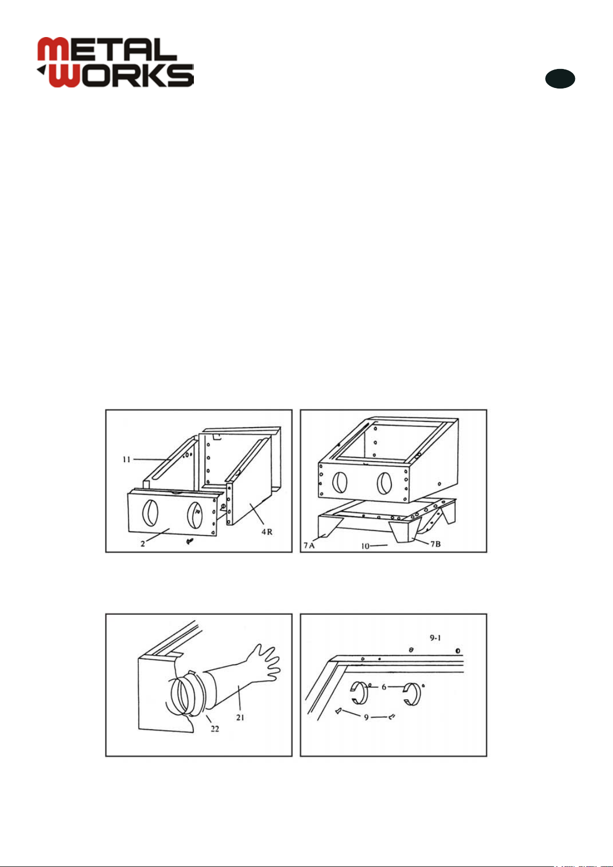
1. Assembleer het voorpaneel (1), het
achterpaneel (3), het rechterpaneel (4R) en
het linkerpaneel (4L) en bevestig deze met
alle schroeven.
2. Duw de basis van de 4 voeten (7A en 7B),
en plaats vervolgens het scherm (23) in de
behuizing.
3. Beveilig het handschoen (21) door middel
van de klem (22) aan het voorpaneel, zoals
afgebeeld.
4. Bevestig de lampklem (6) zoals afgebeeld.
CAT210 - NLFRENES - v2.0 - 16072013
3
NL
®
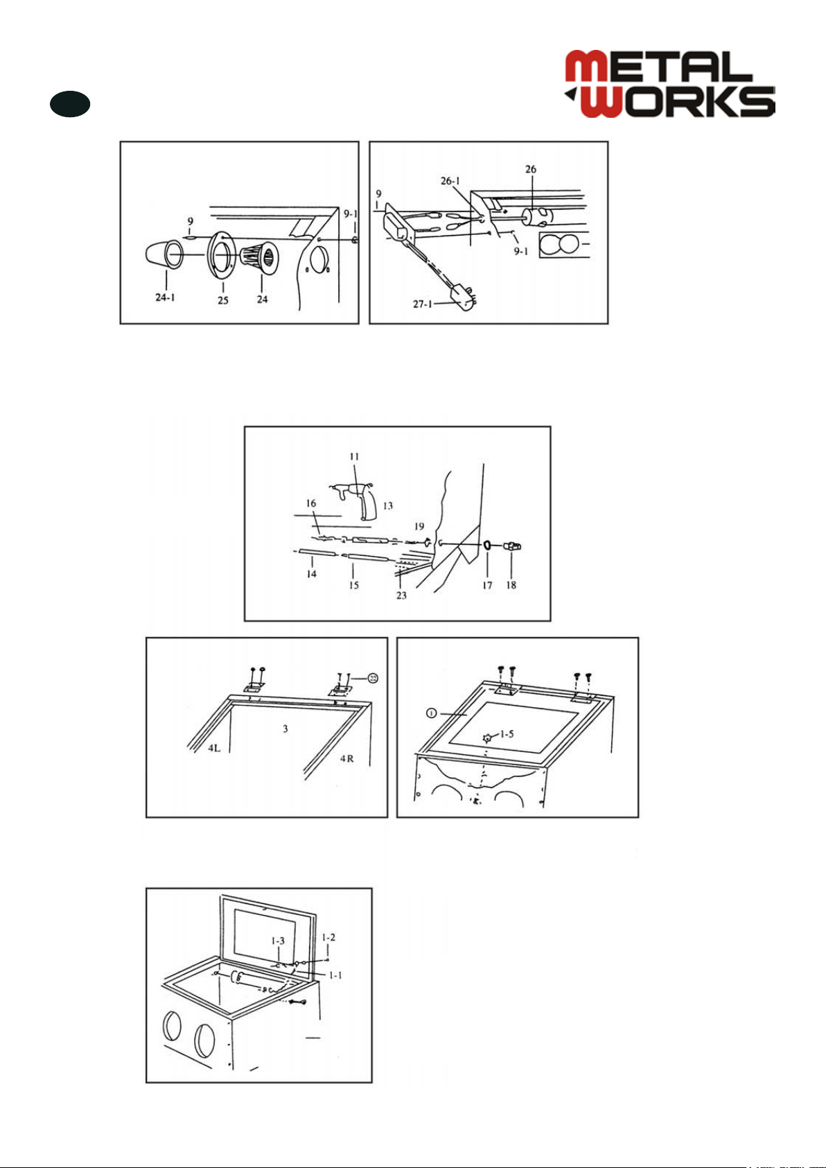
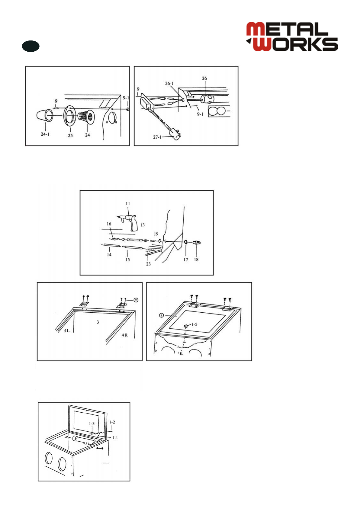
5.Assembleerdelterzoalsafgebeeld. 6.Duwdeuorescentielamp(26)inhaarklem(6),neemdanhet
netsnoer uit het gat door 4L. Gebruik de moer (26-1) op de kabel om
te beveiligen. Sluit dan met het circuit in de aansluitkast (27) aan en
bevestig op het linkerpaneel (4L).
7. Assembleer
het pistool.
8. Na de montage van de cabine,
assembleer de transparante deksel (01),
blokkeer het bewegende deel van het
achterpaneel (03).
9. Plaats de transparante deksel onder
het bewegende deel. Om het handvat te
bevestigen, plaats het stuk (22) in het gat op
het bewegende deel, en druk stevig om aan
de deksel te bevestigen.
10. Open de deksel en bevestig beide
uiteinden van de ketting door middel van
de schroeven en moeren, zoals afgebeeld.
De ketting voorkomt dat de deksel naar
achteren valt, wat deze kan beschadigen.

CAT210 - NLFRENES - v2.0 - 16072013
4
NL
®
3 Voorbereiding
• Plaatshetstraalsysteembijeen115V/60Hz(240V/50Hz)ACstopcontact.Zorgervoor,datdeaansluitinggeschikt
isvooreen3-poligestekker,zodathetapparaatgeaardwordt.Zorgerookvoor,datdestroomvoedinggeschiktis
voorhetgebruikvanditstraalsysteem.Raadpleegeengekwaliceerdeelektricienalsunietoverhetjuistestopcontact
beschikt, en voor alle vragen over de elektrische aansluiting (zie “Veiligheid”).
• Sluit de luchttoevoer van een compressor, die 5 cfm bij 80 psi (5,51 bar) kan handhaven, aan de inlaat op de
rechterkant van de cabine aan. Wegens de veel verschillende luchttoevoersystemen, wordt de koppeling voor de
luchtinlaat niet meegeleverd. Gebruik een koppeling die met uw luchttoevoersysteem past.
De druk mag nooit 100 psi (5,51 bar) overschrijden bij het gebruik van uw zandstraalcabine.
• Controleerdeaansluitingvandeluchttoevoerenvandeslangaandeachterkantvanhetpistool.Zorgerookvoor,
dat de toevoerslang voor de straalkorrels stevig op de spuitmond onderaan het pistool vastzit.
• Plaats niet meer dan 5 kilo schuurmateriaal in het midden van de straalcabine. Een te grote hoeveelheid kan een
vertroebeling van de cabine veroorzaken, straalkorrels kunnen door het afvoergat wegvloeien, of de zandstraling kan
traageninefciëntzijn.
• Met de luchttoevoer aangesloten, alle aansluitingen en verbindingen goed bevestigd, zonder lekkage, bent u klaar
op uw zandstraalcabine te testen.
4 Gebruik
• Zethetwerkstukindecabine.Sluitenvergrendeldedekselvoordatumetdezandstralingbegint.
Zwareletselsvandehuidenogenkunnenveroorzaaktwordendoordezandstraal.
• Zetuwhandenindehandschoenen,neemhetpistoolendrukopdetrekker.Dezandstralingmoetopstarten.Indien
er geen straal is kan het nodig zijn, de spuitmond van het pistool voor een ogenblik te bedekken om de slang te
ontstoppen.
• Nu kunt u met het zandstralen van het werkstuk beginnen. Verplaats de zandstraal voortdurend op het werkstuk, met
een regelmatige en cirkelvormige beweging. De straal mag niet te sterk en geconcentreerd zijn om een overmatige
schuring te voorkomen.
5 Onderhoud
Opgepast: Ontkoppel de lucht- en stroomtoevoer voor ieder onderhoud!
Ieder straalsysteem is gevoelig aan verstopping en slijtage door het gebruik van schuurmaterialen. Om problemen te
voorkomen, controleer regelmatig de volgende punten:
Verstoppingen
Het blaasmondstuk kan door vochtig schuurmateriaal verstopt zijn. Probeer het vochtige schuurmateriaal door middel van
een boor in uw hand te verwijderen.
Indien de toevoerslang voor de straalkorrels verstopt verschijnt, bedek het uiteinde van het pistool om de lucht terug door
de slang te dwingen. Tijdens deze operatie kan stof wegvliegen, dus zorg ervoor, dat de deksel goed gesloten is!
Slijtage
Slijtage wordt meestal opgemerkt wanneer een overmatige hoeveelheid stof in de cabine verschijnt. Stof zal in de
volgende gevallen optreden:
Het straalmateriaal is versleten. Als het niet meer korrelig of sferisch verschijnt, of als er veel brokstukjes van bewerkte
werkstukken met het straalmateriaal gemengd is, vervang het straalmateriaal. Dit wordt meestal opgemerkt wanneer het
straalmateriaal dat uit het pistool komt als een mist in plaats van een straal eruit ziet.
De luchtuitlaat is verstopt of de luchtstroom is geblokkeerd. De reiniging van de luchtuitlaat zou de hoeveelheid stof in de
cabineverminderen.Ditdeelvanhetpistoolkanversletenzijn.Ditiszichtbaarwanneerdestraaltebreedeninefciënt
is. Vervang gewoon de spuitmond.
Vervanging van het transparante pvc paneel
Onderaan de transparante deksel is er een 0,5 mm vervangbaar transparant pvc paneel.
Als u vaststelt, dat dit paneel ondoorzichtig wordt, vervang het om een slechte zicht tijdens het werk te voorkomen.
CAT210 - NLFRENES - v2.0 - 16072013
5
NL
®
6 Storingen
Storingen Oorzaken Oplossingen
Te veel stof in de cabine Luchtuitlaat verstopt of geblokkeerde
luchtstroom.
Schuurmateriaal versleten.
Te veel schuurmateriaal in de cabine.
Losse aansluitingen of verbindingen.
Ontstop de uitlaat en houd deze ver
van wanden.
Vervang het schuurmateriaal.
Verwijder het teveel aan materiaal.
Draai de aansluitingen en
verbindingen vast.
Onregelmatige zandstraling Te veel schuurmateriaal in de cabine.
Vochtigheid in de cabine. Verwijder het teveel aan materiaal.
Controleer de aanwezigheid van
vocht in de luchtslangen.
Ongepastesnelheidofinefciënte
zandstraling Schuurmateriaal versleten.
Druk te laag. Vervang het schuurmateriaal.
Verhoog de ingangsdruk en controleer
dat de regelklep volledig open is.
Statische elektriciteit Droge weeromstandigheden. Laat het werkstuk op de rooster.
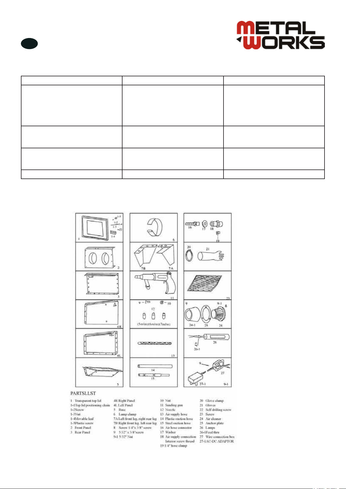
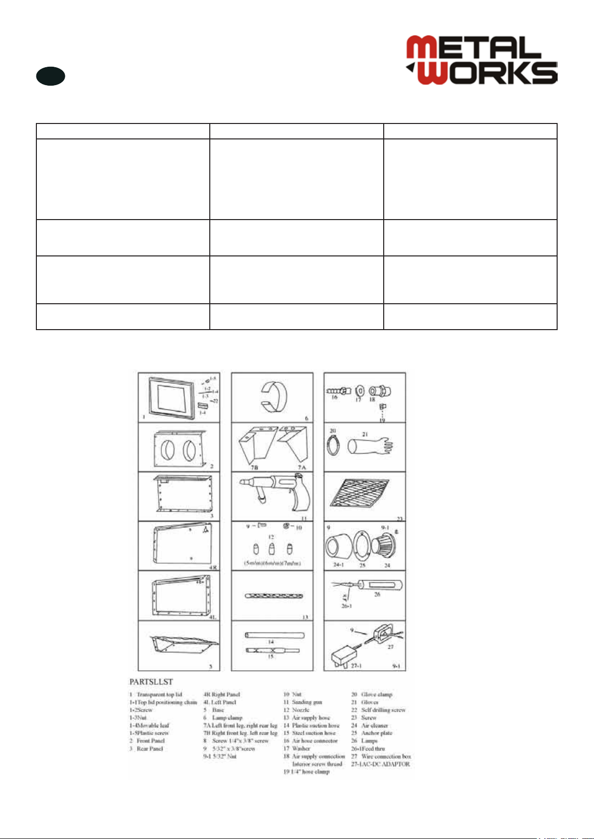
7 Onderdelen

6
®
FR
CAT210 - NLFRENES - v2.0 - 16072013
1 Sécurité
Important: Toute cabine de sablage occasionne des projections importantes de particules abrasives. Pour éviter les
dommages matériels ou corporels, lisez attentivement ce mode d’emploi avant l’assemblage, l’utilisation et l’entretien de
cette cabine de sablage.
Le non-respect des instructions de ce mode d’emploi peut provoquer des blessures de l’opérateur ou endommager le
système de sablage.
• VotrecabinedesablageestconçueUNIQUEMENTpourlenettoyage,lepolissageetlanitionavecdel’abrasif
seccommedesgranulésdeverreoudeplastique.Lerésultatpeutvarierdegrossieràn,enfonctiondelataille
desgranulés.Pourlespiècesdélicates,commencezavecunepressiond’airminimale,and’éviteruneabrasion
excessive.
• Votrecabinedesablageestéquipéed’unecheà3brochesavecconnexionàlaterre,pouréviterleschocs
électriques. Lors du branchement de votre équipement, respectez toutes règles de sécurité en vigueur. La cabine de
sablage doit être branchée à une prise adéquate avec prise de terre. Si une telle prise n’est pas disponible, faites-en
installeruneparunélectricienqualié.Unadaptateurpeutêtreutilisé.Assurez-vousquelelvertdel’adaptateurest
bien connecté à la terre.
• Les matériaux abrasifs sont très glissants et doivent être nettoyés immédiatement pour éviter tout risque de blessure de
l’opérateur.
2 Assemblage
1. Assemblez le panneau avant (2), le
panneau arrière (3), le panneau droit (4R) et
legauche(4L)etxezavectouteslevis.
2. Emboîtez la base des 4 pieds (7A et 7B),
puis placez l’écran (23) dans la cabine.
3. Fixez le gant (21) au moyen de l’attache
(22) au panneau avant, comme illustré. 4. Fixez l’attache de la lampe (6) comme
illustré.

7
®
FR
CAT210 - NLFRENES - v2.0 - 16072013
5.Assemblezleltrecommeillustré. 6.Poussezlalampeuorescente(26)danssonattache(6),puis
sortez le câble électrique par le trou dans le panneau 4L. Utilisez
l’écrou (26-1) inclus sur le câble pour sécuriser, puis connectez
aveclecircuitdansleboîtierélectrique(27)etxezaupanneaude
gauche (4L).
7. Assemblez le
pistolet.
8. Après l’assemblage de la cabine,
assemblez le couvercle transparent (01).
Bloquez la partie mobile du panneau arrière
(03).
9. Placez le couvercle transparent sous la
partie mobile pendant qu’elle est bloquée.
Pourxerlapoignée,placezlapièce(22)
dans le trou sur la partie mobile, et appuyez
fortementpourlaxersurlecouvercle.
10.Ouvrezlecouvercleetxezlesdeux
extrémités de la chaîne au moyen des vis et
écrous, comme illustré. La chaîne empêche
le couvercle de tomber en arrière (ce qui
peut l’endommager).

8
®
FR
CAT210 - NLFRENES - v2.0 - 16072013
3 Préparation
1. Placez l’équipement de sablage près d’une alimentation électrique 115V/60Hz (240V/50Hz) AC. Assurez-vous que
lacheconvient,pourquel’équipementsoitcorrectementbranchéàlaterre.Vériezégalementquel’alimentation
électriqueestsufsantepourvotrecabinedesablage.Adressez-vousàunélectricienqualiésivotreinstallationde
convient pas, ou pour toute question concernant le branchement électrique (voir «Sécurité»).
2. Fixez le tuyau d’alimentation en air d’un compresseur capable de maintenir 5 cfm à 80 psi (5,51 bar) à l’entrée
située du côté droit de la cabine. En raison de la grande variété de systèmes d’alimentation en air, la connexion
pour l’entrée d’air n’est pas fournie. Utilisez une connexion compatible avec votre système d’alimentation en air.
N’utilisez pas votre équipement de sablage avec une pression supérieure à 100 psi (5,51 bar).
3. Vériezleraccordduconduitd’alimentationenairetlaxationdutuyauàl’arrièredupistolet.Assurez-vous
égalementqueletuyaud’alimentationenmatérieldesablageestsolidementxésurl’embout,àlapartieinférieure
du pistolet.
4. Ne mettez pas plus de 5 kilos d’abrasif au centre de la cabine. Une quantité excessive peut provoquer une
opacicationdelacabine,unepartiedumatériaupeuts’échapperparletroud’évacuation,oulesablagepeutêtre
lentetinefcace.
5. Unefoisl’alimentationenairconnectéeettouslesraccordsetjointsbienxéssansrisquedefuite,vousêtesprêtà
tester votre système de sablage.
4 Utilisation
1. Placez la pièce dans la cabine. Fermez et verrouillez bien le couvercle avant de commencer le sablage.
De graves blessures de la peau et des yeux peuvent résulter d’une exposition au jet de matériau de sablage.
2. Après avoir mis vos mains dans les gants, prenez le pistolet et pressez la gâchette. La projection du matériau de
sablage doit commencer. Si rien ne se passe, vous devez peut-être dégager le tuyau en bouchant l’embout du pistolet
pendant quelques instants.
3. À présent, vous pouvez commencer à sabler la pièce. Déplacez le jet de sablage continuellement sur la pièce, en
un mouvement régulier et circulaire. Le jet ne peut pas être trop puissant ou concentré, pour éviter une abrasion trop
importante.
5 Entretien
Important: Débranchez l’alimentation en air et en électricité avant tout entretien !
Tout système de sablage est sujet aux bouchages et à l’usure, à cause de l’utilisation de matériaux abrasifs. Pour éviter
cesproblèmes,procédezrégulièrementauxvéricationssuivantes:
Bouchons
L’embout de sablage peut facilement être bouché par un matériau humide. Essayez d’enlever le matériau humide au
moyen d’un foret que vous tenez à la main.
Si le tuyau d’arrivée de l’abrasif semble bouché, couvrez l’extrémité du pistolet pour forcer l’air à retourner dans ce
tuyau. De la poussière peut s’échapper lors de cette opération, veillez donc à bien fermer le couvercle !
Usure
L’usure se remarque habituellement lorsqu’une quantité excessive de poussière apparaît dans la cabine. De la poussière
se forme dans les cas suivants:
Le matériau de sablage est usé. S’il a perdu son apparence granuleuse ou sphérique, ou s’il y a beaucoup de débris
de pièces sablées qui se mélange au matériau, remplacez-le. En général, ceci se remarque lorsque l’abrasif qui sort de
l’embout a l’aspect d’un brouillard et non d’un jet.
Lasortied’airestbouchéeouleuxd’airestbloqué.Lenettoyagedelasortied’airdevraitréduirelaquantitéde
poussièredanslacabine.Cettepartiedupistoletpeutêtreusée.Ceciestévidentlorsquelejetesttroplargeetinefcace.
Remplacez simplement l’embout.
Remplacement du panneau pvc transparent
Dans le bas du couvercle transparent, il y a un panneau en pvc transparent de 0,5 mm qui peut être remplacé. Si vous
constatez que ce panneau devient opaque, remplacez-le pour éviter d’affecter la visibilité pendant le travail.

9
®
FR
CAT210 - NLFRENES - v2.0 - 16072013
6 Dysfonctionnements
Problèmes Causes Solutions
Excès de poussière dans la cabine Sortied’airbouchéeouuxd’air
bloqué.
Le matériau abrasif est usé.
Trop de matériau abrasif dans la
cabine.
Raccords ou joints desserrés.
Dégagez la sortie d’air et tenez-la
éloignée de toute parois.
Remplacez le matériau.
Enlevez l’excès de matériau.
Resserrez les raccords et les joints.
Sablage irrégulier Excès de matériau abrasif dans la
cabine.
Présence d’humidité dans la cabine.
Enlevez l’excès de matériau.
Vériezlaprésenceéventuelle
d’humidité dans les tuyaux d’air.
Vitesse inadaptée ou sablage
inefcace Le matériau abrasif est usé.
Pression trop basse. Remplacez le matériau.
Augmentez la pression d’entrée
et assurez-vous que la vanne de
commande est complètement ouverte.
Électricité statique Temps sec. Laissez la pièce en cours de sablage
sur la grille.
7 Pièces détachées

10
®
EN
CAT210 - NLFRENES - v2.0 - 16072013
1 Safety
Notice:Anyblastcabinetwillproduceapowerfulowofabrasiveparticles.Toavoidpersonalinjuryandproperty
damage, study this manual thoroughly before assembling, operating or servicing this blast cabinet.
Failure to follow these instructions could result in operator injury as well as damage the blasting system.
• Yourblastcabinetisdesignedforcleaning,polishingandnishingwithdryabrasiveONLY,suchasglassbeador
plasticgranuleabrasives.Thenishescanvaryfromcoarsetoneaccordingtothesizingoftheglassbead.On
delicate parts, start out with minimal air pressure to avoid unnecessary peeling or undesired, excessive abrasion.
• Do notice your blasting system is equipped with a 3-prong grounded plug for protection against shock. When
connecting your unit obey all applicable electrical and safety codes. The blasting system should be plugged
into an adequately grounded 3-prong receptacle. If only a 2-pong receptacle is available, have it replaced with
theapplicablenationalandlocalcodesorordinances.Onlyaqualiedelectricianshouldperformthiswork.A
grounded adaptor can be used. Make sure the green lead of the adaptor is properly attached to a suitable electric
ground.
• Abrasive media is very slippery and should be cleaned up immediately to avoid possible operator injury.
2 Assembling the blast cabinet
1. Connect front panel (2), rear panel (3),
right panel (4R), left panel (4L) and screw up
all of the screws.
2. Connect the base of the four legs (7A and
7B), then put screen (23) in the cabinet.
3. Secure the glove (21) with glove clamp
(22) onto the front panel as illustrated. 4. Connect the lamp clamp (6) as illustrated.

11
®
EN
CAT210 - NLFRENES - v2.0 - 16072013
5.Assemblethelter. 6.Pushtheuorescentlamp(26)intolampclamp(6),thenputthe
electric cord outside the hole through 4L. Use screw nut (26-1) which
is enclosed on the cord to secure, then combine with the circuit inside
the wire connection box (27) and up tight at left panel (4L).
7. Assemble the
blast gun.
8. After you complete the assembly of
the blast cabinet, you shall assemble the
transparent top lid (01), lock up the movable
leaf above the rear panel (03).
9. Upon locking up the movable leaf, put
the transparent top lid under the movable
leaf.Tolockupthehandle,rstputtheitem
(22) though the holes on the movable leaf,
press hard to lock onto the top lid.
10. Open up the top lid and connect the
positioning chain. Please connect the two
ends of the chain with the screw and screw
nut as illustrated. This will prevent the top
lid from falling off (this can damage the top
lid).

12
®
EN
CAT210 - NLFRENES - v2.0 - 16072013
3 Preparation
1. Place the blast system near 115V/60Hz (240V/50Hz) AC electrical outlet. Make sure the receptacle will accept the
3-prong plug, so that the unit will be properly grounded. Also make sure to check the power source is adequate for
use with this blast system. An electrician should be consulted if the proper outlet is not available or if the user in any
way questions the condition of the electrical circuit (see “Safety”).
2. Attach the air supply line from a compressor capable of maintaining 5 cfm at 80 psi (5,51 bar) to the inlet
connection found on the right side of the cabinet. Because the variation in air supply systems, the air inlet coupling is
notprovided.Usetheparticularttingthatiscompatiblewithyourairsupplysystem.
Do not operate the blasting system at over 100 psi (6,89 bar).
3. Checktheairsupplylinettingsandhoseattachmentstotherearofthegun.Alsomakesurethemediasupplyhose
is attached tightly on the nipple on the underside of the gun.
4. Place not more than 10 pounds (5 kg) of abrasive media into the center of the cabinet. Excessive amounts will create
clouded cabinet conditions, blow by of media through the exhaust, or sluggish and ineffective blasting performance.
5. Withtheairsupplyconnected,allttingsandjointsnotleakingandtheunitispluggedin,youarereadytotestthe
blasting system.
4 Use
1. Place the part in the cabinet. Always close and latch the lid after placing the part in the cabinet prior to blasting.
Severe injury to the skin and eyes may result from exposure to the blast stream.
2. Afterputtingyourhandsintothegloves,graspthegunanddepressthetrigger.Thisshouldbegintheblastingow.If
noowisseen,youmayneedtoclearthetubebycoveringthegunnozzlemomentarily.
3. Nowyoumaybeginnishingthepart.Youshouldmovetheblaststreamcontinuouslyoverthepartinanevenand
circularmotion.Theowshouldnotbetoohardorconcentratedtoavoidundesirablepeeling.
5 Maintenance
Note: Disconnect power and air before any maintenance!
All blasting system is prone to plugging or wear because of the abrasive material used and the applications. The
following items should be checked for wear as indicated:
Plugged conditions
The blast nozzle may become plugged from moist media. Try dislodging the media with a drill bit held in your hand. You
need to get rid of the moist media.
Iftheabrasivepick-uphoseappearsplugged,covertheguntipandforcetheairbackthroughthishose.Dustmayyup
when you do this so make sure the lid is down!
Wear conditions
This is usually noted when an excessive amount of dust appears in the cabinet. Dust will occur if:
1. The abrasive blasting media is worn out. If it has lost its granular or spherical appearance or has a lot of debris
from the parts being blasted and mixed in, replace it. This is usually noticed when the abrasive media that exists the
nozzle looks like a smoke cloud coming instead of a stream.
2. Theairoutletventispluggedorairowoutisblocked.Cleaningthisventshouldhelpreducedustinthecabinet.
This gun parts may wear out. This is usually evident when the blast pattern is too wide and ineffective, simply replace
nozzleororice.
To replace the transparent pvc board
At the bottom of parts n° 1 transparent top lid, there is a 0.5 mm replaceable transparent pvc board. When at work, if
the transparent pvc board is getting unclear, it may be replaced with a new one to avoid affecting the sight during work.

13
®
EN
CAT210 - NLFRENES - v2.0 - 16072013
6 Troubleshooting
Problem Cause Remedy
Excessive dust in the cabinet Exhaustventpluggedorairowis
blocked.
Abrasive media worn.
Too much abrasive media inside
cabinet.
Looseairlineorttingconnections.
Clean rear vent and keep vent away
from any wall.
Replace abrasive media.
Remove excess media.
Tightenttingandmakesureairlines
are secure.
Uneven blasting actions Too much abrasive media inside
cabinet.
Moisture present inside the cabinet.
Remove excess media.
Check air line to make sure there is no
moisture in it.
Inadequatespeedorinefciencyof
blast Abrasive media worn.
Pressure too low. Replace abrasive media.
Increase inlet pressure and make sure
control valve is fully opened.
Static electricity Dry weather conditions. Leave the item being cleaned on the
grating.
7 Parts list
14
®
ES
CAT210 - NLFRENES - v2.0 - 16072013
1 Seguridad
Nota:Cualquiercabinachorreadoraproduciráunujopotentedepartículasabrasivas.Paraevitarlesionespersonales
y daños materiales, estudie este manual detenidamente antes de montar, usar o manipular esta cabina.
• Por favor, lea las instrucciones antes de usar este sistema de limpieza!
El incumplimiento de estas instrucciones puede causar daños personales o invalidar el sistema de limpieza.
• Su cabina de limpieza está diseñada para la limpieza, pulido y acabado SOLAMENTE con abrasivo seco, gránulo
abrasivo. Los acabados pueden dar un resultado muy preciso en las partes dependiendo del tamaño del grano de
cristal,comenzarconunamínimapresióndeaireparaevitarunmartilleoinnecesarioounaabrasiónnodeseada.
Elsistemadelimpiezaestáequipadoconunenchufede3clavijasparaproteccióncontrachoqueseléctricos.Al
conectar la unidad siga todas las instrucciones eléctricas y aplique las instrucciones de seguridad, incluyendo el
CódigoEléctricoNacional(NEC)yelOcupationalylaLeydeSeguridadySalud(OSHA).Elsistemadelimpieza
debeserenchufadoenunatomadecorrientecon3clavijasconconexiónatierraadecuada.Sisólounade2
clavijasestádisponible,sustituyaloscódigosyordenanzaslocalesynacionalesaplicables.Sólounelectricista
cualicadodeberealizarestetrabajo.Unadaptadordeconexiónatierrasepuedeutilizar.Asegúresedequeel
cableverdedeladaptadorestácorrectamenteconectadoaunatomaeléctricaadecuadaNota:ElCódigoEléctrico
deCanadáprohíbeelusodeadaptadoresde3clavijas.
• Los medios abrasivos son muy resbaladizos y deben limpiarse de inmediato para evitar posibles lesiones al
operador.
2 Montaje
1. Conecte el panel frontal (2) Panel posterior
(3) a la derecha del panel izquierdo del
panel (4) y el tornillo de seguridad de todos
los tornillos.
2. Conecte la base a las cuatro patas (7A
y 7B) y luego poner la pantalla (23) en el
gabinete.
3. Asegure el guante (21) con la abrazadera
del guante (22) en el panel frontal como la
ilustración.
4. Conecte la pinza de la lámpara (6) como
se muestra.
15
®
ES
CAT210 - NLFRENES - v2.0 - 16072013
5.Instaleelltro. 6.Empujelalámparaurescent(26)haciaadelanteenla
abrazadera de la lámpara (6) el poner el cable eléctrico fuera del
agujero en 4L tuerca uso (26-1), que se adjunta en el cable para
asegurar,acontinuación,secombinanconelcircuitointeriorde
laconexióndelcablecaja(27)yacalycantoenelpaneldela
izquierda (4L).
7. Montar
la pistola
chorreadora
8. Después de completar el montaje
de SBC, entonces se dotarán de los
transparentes a la tapa (01), favor de
encerraralahojamóvilporencimadel
panel trasero (03)
9.Trasencerraralahojamóvilpusolatapa
superior transparente debajo de la hoja
móvil.parabloquearlaprimeraBandlea
continuación,ponermaterial(22)através
delosoriciosdelaprensadelahojamóvil
difícildebloquearalatapasuperior.
10. Abrir la tapa superior y conectar la cadena
posicionamiento por favor conect los dos extremos
de la cadena con th tornillo y la tuerca de tornillo
como se ilustra este Con evitar que la tapa superior se
caiga y tiene un suiking Forer whrn que se abre (si la
sorprendente es demasiado grande puede causar el
daño de la tapa superior).

16
®
ES
CAT210 - NLFRENES - v2.0 - 16072013
3 Preparación
1. Colocarsistemadechorreocerca115V/60Hz(240V/50Hz)tomaeléctricadeCAAsegúresedequeelrecipiente
acepta el enchufe de 3 clavijas, por lo que la unidad debe estar correctamente conectado a tierra. También,
asegúresedecomprobarquelafuentedealimentacióneslaadecuadaparasuusoconestesistemadelimpieza,un
electricista debe ser consultado si no está disponible la toma de corriente adecuada o el usuario tiene en cualquier
pregunta sobre el circuito eléctrico (vea la nota en el manual)
2. Fijarlalíneadesuministrodeairedeuncompresorcapazdemantener5cfma80psialaconexióndeentrada
queseencuentraenelladoderechodelarmario.Debidoalavariaciónenlossistemasdesuministrodeaire,nose
proporciona el acoplamiento de entrada de aire. Utilice el accesorio especial que sea compatible con su sistema de
suministro de aire.
No haga funcionar el sistema de limpieza a más de 100 psi.
3. Comprobarlasconexionesdelalíneadesuministrodeaireyaccesoriosdemangueraenlapartetraseradela
pistola.Tambiénasegúresedequelamangueradesuministrodepapelsejarmementeenlaparteinferiordela
pistola.
4. No colocar más de 10 litros de medios abrasivos en el centro de la caja. Si se excede en las cantidades, obstruirá y
ralentizará la limpieza o golpeará los sistemas hasta producir escapes.
5. Conectado con el suministro de aire, todos los accesorios y las estructuras sin fugas y la unidad enchufada; ya está
listo para poner a prueba el sistema de limpieza. Ahora siga estos pasos para la puesta en marcha.
4 Utilizar
• Colocar la pieza en la cabina. Cerra siempre con el pestillo la tapa antes de iniciar el sistema de limpieza. No
hacerlo puede provocar lesiones graves en la piel y en los ojos.
• Después de poner las manos en los guantes, agarre la pistola y apriete el gatillo. Este debe iniciar a desprender el
ujodechorro.Sinohayujo,puedequelaarenahayaobstruidolaboquillamomentáneamente.
• Ahora usted puede comenzar a terminar la pieza. Debe mover la pieza. Desprenda corriente con un movimiento
uniforme y circular de manera continua. El caudal no debe ser demasiado duro o concentrado para evitar martilleo
indeseable.
5 Mantenimiento
Nota:Desconectelaenergíayelaireantesdeiniciarelmantenimiento!
Todoslossistemasdelimpiezasonpropensosalaobstruccióndebidoaldesgastedelmaterialabrasivoutilizadoyde
las aplicaciones. Los siguientes puntos deben ser comprobados para evitar el desgaste como se indica:
Condiciones de conexión
Si el tubo de recogida abrasivo aparece conectado, cubra la punta de la pistola y fuerce el aire de nuevo a través de
este tubo. El polvo puede volar cuando hace esto para asegurarse de que la tapa está hacia abajo.
Condiciones de desgaste
Esto generalmente se nota cuando una cantidad excesiva de polvo aparece en la cabina. El polvo se producirá si:
1. Se desgastan los medios de chorreo abrasivo. Si ha perdido su aspecto granular o esférico o los tiene mezclados
conunmontónderestosdelaspiezas,reemplaceelmaterialdelimpueza.Estogeneralmentesenotacuandolos
materiales abrasivos que salen de la boquilla se parecen a una nube de humo en lugar de una corriente.
2. Lasalidadeaireestáatascadaoelujodeaireestábloqueado.Limpielaventilaciónparareducirelpolvoenla
cabina.Estaspiezassepuedenllevaracabo.Estosueleserevidentecuandoelpatróndechorreoesdemasiado
amplioeinecaz,simplementereemplacelaboquillauoricio.
Para reemplazar la placa de PVC transparente
En la parte inferior de las partes de n. 1 tapa transparente superior, hay una placa reemplazable PVC transparente de
0,5 mm, cuando acaba el trabajo, si la placa de PVC transparente se está clara, puede ser reemplazada por una nueva
para evitar afectar a la vista durante el trabajo.
17
®
ES
CAT210 - NLFRENES - v2.0 - 16072013
6 Solución ed problemas
Problema Causa Solución
Exceso de polvo en la caja Laconexióndeventilacióndeescapeoel
ujodeaireestábloqueado
Medios abrasivos usados
Demasiado abrasivos dentro de la cabina
Lalíneadeairesueltosoconexionesde
los accesorios
Abertura trasera limpia y tener rienda
suelta a cualquier pared
Sustitucióndeloselementosabrasivos
Eliminar el exceso de elementos
Ajusteapropiadoyasegúresequela
conexióndeaireessegura
Acciones chorro irregulares Demasiado abrasivos dentro de la cabina
La humedad en el interior de la cabina Retire el exceso de elementos
Extraer humedad
Velocidadinadecuadaoenineciencia
de chorro Medios abrasivos usados
Presióndemasiadobaja
Sustitucióndeloselementosabrasivos
Aumentarlapresióndeentradayhacer
que la válvula de control esté totalmente
abierta
Electricidad estática Condiciones atmosféricas secas Deje el elemento que se está
limpiado en la rejilla
7 Recambios

CAT210 - NLFRENES - v2.0 - 16072013
18
®
Fabrikant/Invoerder
Fabricant/Importateur
Manufacturer/Retailer
Fabricante/Importador
Verklaart hierbij dat het volgende product :
Déclare que le produit suivant :
Hereby declares that the following product :
Declara que los siguientes productos:
Product
Produit
Product
Producto
Zandstraalcabine
Cabine de sablage
Sandblast cabinet
Cabina chorreadora
Order nr. :
Geldende CE-richtlijnen
Normes CE en vigueur
Relevant EU directives
Normativas de la CE
2006/42/EC
Overeenstemt met de bestemming van de hierboven aangeduide richtlijnen - met inbegrip van deze
betreffende het tijdstip van de verklaring der geldende veranderingen.
Répond aux normes générales caractérisées plus haut, y compris celles dont la date correspond aux
modicationsenvigueur.
Meets the provisions of the aforementioned directive, including, any amendments valid at the time of this
statement.
CumplelasdisposicionesdedichaDirectiva,incluyendolasmodicacionesvigentesenelmomentode
estadeclaración.
Moeskroen, Mouscron, 16/07/2013
Bart Vynckier
VYNCKIER TOOLS NV
Aslak S.L.
Salvador Gil i Vernet, 5
Pol. Ind. Can Torres i Can Llobet
ES-08192 Sant Quirze del Vallès - Barcelona
Vynckier Tools nv.
Avenue Patrick Wagnon, 7
ZAEMdeHaureu
B-7700 Mouscron - Moeskroen
EG conformiteitsverklaring
Déclaration de conformité CE
EC declaration of conformity
Declaración de conformidad según la CE
CAT 210 (754751210)
FR
EN
NL
ES
This manual suits for next models
1
Table of contents
Languages:
Other Metalworks Power Tools manuals


Popular Power Tools manuals by other brands

Evolution
Evolution Rage 7 Original instructions

Parkside
Parkside PAGG 4 A1 Translation of the original instructions

Skil
Skil 3280 Series Original instructions

BorMann
BorMann BPH1000 user manual

Gardena
Gardena ComfortCut 30 operating instructions

Chicago Electric
Chicago Electric 47937 Assembly and operating instructions


