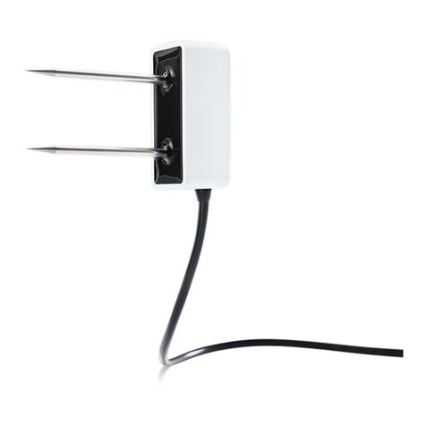
METER TEROS 12 User manual

TEROS 12

i
TABLE OF CONTENTS
1. Introduction..............................................................................................1
2. Operation ...................................................................................................2
2.1 Installation.................................................................................................2
2.2 Connecting.................................................................................................7
2.2.1 Connect to METER Data Logger.........................................................7
2.2.2 Connect to a Non-METER Logger ......................................................8
2.3 Communication..........................................................................................9
3. System....................................................................................................... 10
3.1 Specifications ..........................................................................................10
3.2 Components.............................................................................................13
3.3 Theory ......................................................................................................14
3.3.1 Volumetric Water Content ...............................................................14
3.3.2 Temperature....................................................................................15
3.3.3 Electrical Conductivity ....................................................................15
3.3.4 Converting Bulk EC to Pore EC.........................................................15
3.3.5 Pore Water Versus Saturation Extract EC ........................................16
4. Service....................................................................................................... 18
4.1 Calibrations..............................................................................................18
4.1.1 Mineral Soils...................................................................................18
4.1.2 Soilless Media.................................................................................18
4.1.3 Apparent Dielectric Permittivity......................................................19
4.2 Cleaning ...................................................................................................19
4.3 Troubleshooting........................................................................................19
18225-01
4.26.2018

ii
TEROS 12
4.4 Customer Support....................................................................................20
4.5 Terms and Conditions...............................................................................21
References .................................................................................................... 22
Index ................................................................................................................. 23

iii

1
TEROS 12
1. INTRODUCTION
Thank you for choosing the TEROS 12 Soil Moisture and Electrical Conductivity (EC) and
Temperature sensor.
The TEROS 12 sensor is designed to be installed in mineral soils, many types of growing
media, and other porous materials. This manual guides the customer through the sensor
features and describes how to use the sensor successfully.
TEROS 12 APPLICATIONS
• Volumetric water content (VWC) measurement
• Soil/substrate water balance
• Irrigation management
• Soil EC measurement
• Soil/substrate temperature measurement
• Solute/fertilizer movement
Prior to use, verify the TEROS 12 arrived in good condition. METER recommends testing the
sensors with the data logging device and software before going to the field.

2
OPERATION
2. OPERATION
Please read all instructions before operating the TEROS 12 to ensure it performs to its full
potential.
SAFETY PRECAUTIONS
METER sensors are built to the highest standards. Misuse, improper protection, or improper
installation may damage the sensor and possibly void the manufacturer’s warranty. Before
integrating the TEROS 12 into a system, follow the recommended installation instructions
and have the proper protections in place to safeguard sensors from damage. If installing
sensors in a lightning-prone area with a grounded data logger, see the application note
Lightning surge and grounding practices.
2.1 INSTALLATION
Follow the steps listed in Table 1 to set up the TEROS 12 and start collecting data. For more
detailed installation information consult the TEROS Sensors Best Practices Installation Guide.
Table 1 Installation
Tools Needed
Auger or Shovel
Secure Mounting Location for Data Logger and Cable
Optional Tool
Borehole Installation Tool
jack
cradle
carriage
shaft
actuator
lever
flashlight
TEROS
sensor

3
TEROS 12
Table 1 Installation (continued)
Preparation
Determine Best Installation Method
There are several methods for installing soil moisture sensors. These methods
are described in Table 2.
Avoid Putting any Metal in Between the Sensor and the Ferrite Core
Any metal located between the sensor and the ferrite core can interfere with
the TEROS 12 VWC measurement.
Check Sensor Functionality
Plug the sensor into the data logger (Section2.2) to make sure the sensor is
operating as expected.
Conduct System Check
Verify all sensors read within expected ranges. To validate both sensor
function and logger functionality, take a sensor measurement in air and
water. The TEROS 12 will read ~0.70 m3/m3in water and a slightly negative
value in air.
Installation
There are several methods for installing soil moisture sensors (Table 2). Keys to
a good installation and collecting good soil moisture data are described below.
Create Hole
Avoid interferring objects. If the TEROS 12 is installed near large metal objects
they can affect the sensor function and distort readings. Avoid large objects
like roots or rocks that could potentially bend the needles.
Auger or trench a hole to the desired sensor installation depth and direction
according to the installation method desired.
Insert Sensor
ATTENTION! Minimize air gaps around the sensor. Air gaps around the sensor
needles will result in low readings of soil moisture.
1. Load the TEROS 12 using the Borehole Installation Tool (BIT).
NOTE: The BIT provides a significant amount of mechanical advantage. See
Table2 for instruction on installing the TEROS 12 without the BIT.
2. Lower the tool into the hole or trench with the back of the tool supported
by the far wall.
3. Pull the tool lever to activate the jack and insert the sensor into the sidewall.
WARNING: When installing sensors in rocky soils, use care to avoide bending sensor needles.
The soil closest to the sensor has the strongest inuence on readings. It is ideal
to install the sensor in the native soil to get accurate soil moisture readings.

4
OPERATION
Table 1 Installation (continued)
Installation
(continued)
Sensor orientation. When the TEROS 12 sensor is installed, it may be
positioned in any direction (needles aligned horizontally or vertically). However,
installing the sensors with the needles in a horizontal position (as shown
below) will provide the least restriction to water ow through soil because the
water will ow through the soil directly to the needles.
Sensor body vertical and needles horizontal
Because of the shape of the sensor electromagnetic eld, installing the
sensor with the body oriented vertically will integrate more soil depth into
the soil moisture measurement. Installing the sensor with the body oriented
horizontally (on its side) will provide measurements at a more discreet depth.
See Measurement volume of METER volumetric water content sensors for
more information on sensor measurement volume.
Backll the Hole
Return soil to the hole, packing the soil back to its native bulk density.
Do not hit the ferrite core as this could potentially pull the sensor out of the soil.
Connect to Logger
Connect the 3.5-mm stereo plug connector into a stereo port on METER
data logger.
METER data loggers will automatically recognize TEROS sensors.
Use ZENTRA Utility software (Section2.2) to congure desired measurement
intervals and verify proper sensor identication by the logger.
Click SCAN in ZENTRA Utility to verify the TEROS 12 is active and providing
reasonable readings based on soild conditions.
Verify that these readings are reasonable based on soil conditions.
To connect to a non-METER data logger, refer to the TEROS 12 Integrator Guide.

5
TEROS 12
Table 1 Installation (continued)
Installation
(continued)
Secure and Protect Cables
Secure and protect cables with PVC casing or exible conduit to protect
against damage from rodents or driving over sensor cables.
Secure Excess Cable
To prevent loose cabling from being inadvertently snagged or tripped over,
gather and secure excess cable to the mounting mast in one or more places.
Tie excess vertical cable to the data logger mast to ensure cable weight does
not cause sensor to unplug.
Relieve Cable Strain
To relieve strain on the connections, leave the cables a little loose between the
logger and the closest secured point on the mast. This will allow for thermal
expansion and contraction of the cable without potentially pulling the stereo
connection out of the logger.
ERROR
OK
TEST
(–)
(+)
(–)
(+)
(–)
(+)
(+)
(–)
(+)
(–)
P1 P2 P3 P4 P5 P6
Securing excess cable
Table 2 contains brief descriptions for typical installation methods. Each has its own
advantages and disadvantages. For more information about which installation method
is best for specific applications, please see the TEROS 12 Installation Guide or contact
Customer Support.

6
OPERATION
Table 2 Installation methods
Borehole
This method uses the Borehole
Installation Tool (Table 1) that
allows a prole of soil moisture
sensors to be installed at
different depths within a single
augered borehole. A 10-cm (4-in)
borehole is augered vertically at
the measurement location. The
Borehole Installation Tool is then
used to install the sensors in the
sidewall of the borehole.
NOTE: The borehole method
requiresspecialized installation
toolavailable from METER ifinstalling
at depths greater than50cm.
Advantage
Minimizes soil
disturbance at
measurement
site.
Disadvantage
Requires a
specialized
installation
tool that can
be rented from
METER.
Trench
The trench installation method is
best for shallow installations (less
than 40 cm). This requires digging
a trench with a shovel, excavator,
etc.The trench needs to be dug to
the depth of the deepest installed
sensor. For deep installations, this
may require a large trench. The
sensor is then installed carefully
by hand into the undisturbed soil
of the trench sidewall. The trench
is then carefully backlled to
preserve the bulk density of the
soil and to avoid dislodging the
installed sensor by accidentally
snagging the ferrite core.
Advantage
Does not
require
specialized
equipment.
Disadvantage
Large soil
disturbance at
measurement
site.
Potentially
large
excavation
effort.

7
TEROS 12
2.2 CONNECTING
The TEROS12 works most efficiently with METER ZENTRA, EM60, or Em50 data loggers. The
TEROS12 can also be used with other data loggers, such as those from Campbell Scientific,
Inc. For extensive directions on how to integrate the sensors into third-party loggers, refer to
the TEROS 12 Integrator Guide.
TEROS12 sensors require an excitation voltage in the range of 4 to 15VDC and operate at a
4VDC level for data communication. TEROS 12 can be integrated using SDI-12 protocol. See
the TEROS 12 Integrator Guide for details on interfacing with data acquisition systems.
TEROS12 sensors that are ordered for use with ZENTRA, EM60, or Em50 data loggers come with
a 3.5-mm stereo plug connector (Figure1) to facilitate easy connection with METER loggers.
Ground
Data
Power
Figure1 Stereo plug connector
The TEROS12 sensor comes standard with a 5-m cable. It may be purchased with custom
cable lengths for an additional fee (on a per-meter basis). This option eliminates the need
for splicing the cable (a possible failure point). However, the maximum recommended length
is75 m.
2.2.1 CONNECT TO METER DATA LOGGER
The TEROS 12 sensor works seamlessly with METER ZENTRA, EM60, or Em50 data loggers.
Logger configuration may be done using either ZENTRA Utility (desktop and mobile
application) or ZENTRA Cloud (web-based application for cell-enabled ZENTRA data loggers).
1. Plug the 3.5-mm stereo plug connector into one of the sensor ports on the logger.
2. Using the appropriate software application, congure the chosen logger port for
TEROS12.
3. Set the measurement interval.
ZENTRA, EM60, or Em50 data loggers measure the TEROS 12 every minute and return the
minute-average data across the chosen measurement interval. TEROS 12 data can be
downloaded from these loggers using either ZENTRA Utility (desktop and mobile application)
or ZENTRA Cloud (web-based application for cell-enabled data loggers).

8
OPERATION
2.2.2 CONNECT TO A NON-METER LOGGER
The TEROS 12 can be used with non-METER (third-party) data loggers. Refer to the third-
party logger manual for details on logger communications, power, and ground ports.
The TEROS 12 Integrator Guide provides detailed instructions on connecting sensors to
non-METER loggers.
TEROS 12 sensors can be ordered with stripped and tinned (pigtail) connecting wires for use
with screw terminals. Connect the TEROS 12 wires to the data logger illustrated in Figure2,
with the supply wire (brown) connected to the excitation, the digital out wire (orange) to a
digital input, and the bare ground wire to ground.
Ground (bare)
Data (orange)
Power (brown)
Figure2 Pigtail wiring
Switched
4–15 VDC
Digital
In
Data Logger
G
Data
(orange)
Ground
(bare)
Power
(brown)
Figure3 Wiring diagram
NOTE: The acceptable range of excitation voltages is from 4 to 15 VDC.To read TEROS 12 sensors with Campbell
Scientific, Inc. data loggers, power the sensors from a switched 12 V port or a 12 V port if using a multiplexer.

9
TEROS 12
If the TEROS 12 cable has a standard 3.5-mm stereo plug connector and will be connected to
a non-METER data logger, please use one of the following two options.
Option 1
1. Clip off the 3.5-mm stereo plug connector on the sensor cable.
2. Strip and tin the wires.
3. Wire it directly into the data logger.
This option has the advantage of creating a direct connection with no chance of the sensor
becoming unplugged. However, it then cannot be easily used in the future with a METER
readout unit or data logger.
Option 2
Obtain an adapter cable from METER.
The adapter cable has a connector for the stereo plug connector sensor jack on one end and
three wires (or pigtail adapter) on the other end for connection to a data logger. The stripped
and tinned adapter cable wires have the same termination as seen in Figure3; the brown
wire is excitation, the orange is output, and the bare wire is ground.
NOTE: Secure the 3.5-mm stereo plug connector to the pigtail adapter connections to ensure the sensor does not
become disconnected during use.
2.3 COMMUNICATION
The TEROS 12 sensor communicates using two different methods:
DDI serial string
SDI-12 communication protocol
To obtain detailed instructions, read the TEROS 12 Integrator Guide.

10
SYSTEM
3. SYSTEM
This section reviews the components and functionality of the TEROS 12 sensor.
3.1 SPECIFICATIONS
MEASUREMENT SPECIFICATIONS
Volumetric Water Content (VWC)
Range
Mineral soil calibration 0.00–0.70 m3/m3
Soilless media
calibration
0.0–1.0 m3/m3
Apparent dielectric
permittivity (εa)
1 (air) to 80 (water)
NOTE: The VWC range is dependent on the media the sensor is calibrated to. A custom calibration will
accommodate the necessary ranges for most substrates.
Resolution 0.001 m3/m3
Accuracy
Generic
calibration
±0.03 m3/m3typical in mineral soils that have solution
EC <8 dS/m
Medium specific
calibration
±0.01–0.02 m3/m3in any porous medium
Apparent dielectric
permittivity (εa)
1–40 (soil range) , ±1 εa (unitless)
40–80, 15% of measurement
Dielectric Measurement Frequency
70 MHz
Temperature
Range −40 to 60 °C
Resolution 0.1 °C
Accuracy ±1 °C
Bulk Electrical Conductivity (ECb)
Range 0–10 dS/m (bulk)
Resolution 0.001 dS/m
Accuracy ±5% of measurement

11
TEROS 12
Output
DDI serial or SDI-12 communications protocol
Data Logger Compatibility
Any data acquisition system capable of 4.0- to 15-VDC power
and serial or SDI-12 communication
PHYSICAL SPECIFICATIONS
Dimensions
Length 9.4 cm (3.70 in)
Width 2.4 cm (0.95 in)
Height 7.5 cm (2.95 in)
Needle Length
5.5 cm (2.17 in)
Cable Length
5 m (standard)
75 m (maximum custom cable length)
NOTE: Contact Customer Support if a nonstandard cable length is needed.
Connector Types
3.5-mm stereo plug connector or stripped and tinnedwires
ELECTRICAL AND TIMING CHARACTERISTICS
Supply Voltage (VCC to GND)
Minimum 4.0 VDC
Typical NA
Maximum 15.0 VDC
Digital Input Voltage (logic high)
Minimum 2.8 V
Typical 3.6 V
Maximum 3.9 V

12
SYSTEM
Digital Input Voltage (logic low)
Minimum –0.3 V
Typical 0.0 V
Maximum 0.8 V
Power Line Slew Rate
Minimum 1.0 V/ms
Typical NA
Maximum NA
Current Drain (during 25-ms measurement)
Minimum 3.0 mA
Typical 3.6 mA
Maximum 16.0 mA
Current Drain (while asleep)
Minimum NA
Typical 0.03 mA
Maximum NA
Operating Temperature Range
Minimum –40 °C
Typical NA
Maximum 60 °C
NOTE: Sensors may be used at higher temperatures under certain conditions; contact Customer Support
for assistance.
Power-Up Time (DDI serial)
Minimum 80 ms
Typical NA
Maximum 100 ms
Power-Up Time (SDI-12)
Minimum NA
Typical 245 ms
Maximum NA

13
TEROS 12
Measurement Duration
Minimum 25 ms
Typical NA
Maximum 50 ms
COMPLIANCE
Manufactured under ISO 9001:2015
EM ISO/IEC 17050:2010 (CE Mark)
2014/30/EU and 2011/65/EU
EN61326-1:2013 and EN55022/CISPR 22
3.2 COMPONENTS
The TEROS 12 sensor measures soil moisture, temperature, and EC of soil using stainless
steel needles (Figure4). TEROS 12 sensors measure soil moisture between Needle 1 and
Needle 2 and EC between Needle 2 and Needle 3. Temperature is measured with an
embedded thermistor in Needle 2. These sensors have a low power requirement, which
makes them ideal for permanent burial in the soil and continuous reading with a data logger
or periodic reading with a handheld reader.
Ferrite
core
Needle 1
Thermistor
Needle 2
Needle 3
VWC
EC
Figure4 TEROS 12 sensor

14
SYSTEM
A ferrite core positioned on the TEROS 12 sensor cable 7.6 cm (3 in) away from the sensor
head is utilized to isolate the sensor from any interferences in the system. This mitigates any
potential noise from the system on the measured sensor data. It is important to not attach
anything to the section of cable between the sensor head and the ferrite core as this may
influence the measurements.
The TEROS 12 VWC measurement sensitivity is contained within a 1,010 mL volume roughly
depicted in Figure5. Please see the application note Measurement volume of METER
volumetric water content sensors (https://www.metergroup.com/environment/articles/
measurement-volume-meter-volumetric-water-content-sensors) for testing protocol and
more thorough analysis.
3 cm
3 cm
3 cm
1 cm
1 cm
7.5 cm
9.3 cm
3 cm
Figure5 VWC volume of inuence
NOTE: The TEROS 12 provides instantaneous or near-instantaneous measurements; however, because of the
sensitivity of the measurement of the sensor head, the TEROS 12 is not well suited for spot measurements of VWC.
3.3 THEORY
The following sections explain the theory of VWC, temperature, and EC measured by
TEROS12.
3.3.1 VOLUMETRIC WATER CONTENT
TEROS 12 sensors use an electromagnetic field to measure the dielectric permittivity of the
surrounding medium. The sensor supplies a 70-MHz oscillating wave to the sensor needles,
which charge according to the dielectric of the material. The charge time is proportional to
substrate dielectric and substrate VWC. The TEROS 12 microprocessor measures the charge
time and outputs a raw value based on the substrate dielectric permittivity. The raw value is
then converted to VWC by a calibration equation specific to the substrate (Section 4.1).

15
TEROS 12
3.3.2 TEMPERATURE
The TEROS 12 uses a thermistor in the center needle to take temperature readings. This is
more important for measurements near the surface where temperature changes are faster.
The TEROS 12 sensor output temperature is in degrees Celsius unless otherwise stated in
the data logger program, such as in preferences in the ZENTRA software.
NOTE: Even though the sensor head is white, in direct sunlight, the temperature measurement may read high. Use
caution when installing the sensor with the sensor head in the sun.
3.3.3 ELECTRICAL CONDUCTIVITY
EC is the ability of a substance to conduct electricity and can be used to infer the amount
of ions that are present in solution. EC is measured by applying an alternating electrical
current to two electrodes and measuring the resistance between them. Bulk EC is
derived by multiplying the inverse of the resistance (conductance) by the cell constant
(the ratio of the distance between the electrodes to their area). TEROS 12 sensor bulk
EC measurements are normalized to EC at 25 °C. The bulk EC measurement is factory
calibrated to be accurate within ±3% of measurement from 0 to 20 dS/m. This range is
adequate for most soil and growth substrate applications.
EC measurements above 10 dS/m are sensitive to contamination of the electrodes by skin
oils, etc. Be sure to read Section 4.2 about sensor cleaning if measuring the EC of salty soils.
3.3.4 CONVERTING BULK EC TO PORE EC
For many applications, it is advantageous to know the EC of the solution contained in the
soil pores (p
), which is a good indicator of the solute concentration in the soil. Traditionally,
p
is obtained by extracting pore water from the soil and measuring p
directly, a time-
consuming and labor-intensive process. The TEROS 12 sensor measures the EC of the bulk
soil surrounding the sensors (b
). A considerable amount of research has been conducted to
determine the relationship between b
and p
. Hilhorst (2000) took advantage of the linear
relationship between the soil bulk dielectric permittivity (b
) and b
to accurately convert b
to p
if the b
is known. The TEROS 12 sensor measures b
and bnearly simultaneously in the
same soil volume. Therefore, the TEROS12 is well-suited to this method.
The pore water conductivity (p ) is determined from Equation 1(see Hilhorst 2000 for derivation):

16
SYSTEM
Equation 1
σp=
ε
p
σ
p
ε
b
−ε
αb=0
where
pis the pore water EC (dS/m),
pis the real portion of the dielectric permittivity of the soil pore water (unitless),
bis the bulk EC (dS/m) measured directly by the TEROS 12,
bis the real portion of the dielectric permittivity of the bulk soil (unitless), and
b = 0 is the real portion of the dielectric permittivity of the soil when bulk ECis0 (unitless).
Dielectric permittivity of the soil pore water (b
) is calculated from soil temperature using
Equation 2:
Equation 2
εp=80.3−0.37×Tsoil −20
( )
where Tsoil is the soil temperature (°C) measured by the TEROS 12.
Finally, b = 0 is an offset term loosely representing the dielectric permittivity of the dry
soil. Hilhorst (2000) recommended that b = 0 = 4.1 be used as a generic offset. Hilhorst
(2000) offers a simple and easy method for determining b = 0 for individual soil types, which
improves the accuracy of the calculation of pin most cases.
METER testing indicates that the method for calculating p(Equation 1) results in good
accuracy (±20%) in moist soils and other growth media. In dry soils, where VWC is less
than about 0.10 m3/m3, the denominator of Equation 1becomes very small, leading
to large potential errors. METER recommends that pnot be calculated in soils with
VWC<0.10 m3/m3using this method.
3.3.5 PORE WATER VERSUS SATURATION EXTRACT EC
As noted in Section3.3.4, pore water EC can be calculated from bulk EC using the sensor-
measured dielectric permittivity of the medium. However, pore water EC is not the same as
saturation extract EC.
Pore water EC is the EC of the water in the pore space of the soil. This could be measured
directly if the soil was squeezed under high pressure to force water out of the soil matrix and
that water was collected and tested for EC.
Table of contents
Other METER Accessories manuals

METER
METER HYDROS 21 GEN 1 User manual
METER
METER TEROS 54 User manual

METER
METER TEROS 21 User manual
METER
METER TEROS 11 User manual

METER
METER TEROS 11 Assembly Instructions
METER
METER TEROS VERIFICATION CLIP User manual

METER
METER TEROS 21 Assembly Instructions

METER
METER AROYA User manual

METER
METER ATMOS 14 User manual
METER
METER ATMOS 14 User manual


