manuals.online logo
Brands
  1. Home
  2. •
  3. Brands
  4. •
  5. METER
  6. •
  7. Accessories
  8. •
  9. METER TEROS 54 User manual

METER TEROS 54 User manual

TEMPLATE USE INSTRUCTIONS
1. MODIFY COVER PAGE (bottom half of page 1)
a. Delete current image
b. Select Rectangle Frame (frame with X through it)
c. Place product image file
1. Select FILE > PLACE
2. Locate product image file
3. Select product image file to place it in Rectangle Frame.
NOTE: Product Image is created by Marketing
(Manu in Germany or Kristi in Pullman)
d. Update Product Name and Product Category
2. MODIFY EMAIL and PHONE # on BACK PAGE, if necessary (top half, page 2)
3. Edit Page 2, including updating the firmware and software numbers in the
ATTENTION box. Work with Product Owner to get correct information for all
sections.
4. EXPORT to PDF
a. Select FILE > EXPORT
b. Select METER QS PRINT
c. In PDF file, Rotate page 1 (cover & back pg) so the Cover page is on the
top half of the page, upside down and the back page is on the bottom
half of the page, right side up
Turn Template guides on/off in Layers window.
TEMPLATE SIZE and TRIM Information
Document size is 8.00” wide x 5.25” tall when folded.
Document size unfolded is 8.00” wide x 10.5” tall.
Most current template file located at https://drive.google.com/drive/u/1/
folders/1E_GxRGeCpiOxpYvXSqP4a4VwvgxES5v8 (date code is
10.8.2019 in file name).
When cutting, the Print shop should do the following:
1 Cut the left side (when looking at the document, side Logo is on) 8.25
inches from the RIGHT side.
2 Cut the right side (when looking at the document) 8 inches from the
LEFT side.
3 Score the sheet in the middle so Gray side and Front Page are equal in
size and no gray or blue shows where it shouldn’t.
4 With the document folded at score line, cut the bottom with gray side
face up, 5.25 inches from the folded edge.
SUPPORT
Have a question or problem? Our support team can help.
We manufacture, test, calibrate, and repair every instrument in house. Our scientists and
technicians use the instruments every day in our product testing lab. No matter what your
question is, we have someone who can help you answer it.
NORTH AMERICA
Email: support.environment@metergroup.com
Phone: +1.509.332.5600
EUROPE
Email: support.europe@metergroup.com
Phone: +49 89 12 66 52 0
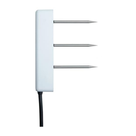
®TEROS 54
SOIL WATER CONTENT PROFILE
3. Check Sensor and
ProtectCables
Plug the probe into the data
logger and use the SCAN function
in the software to do a quick
check of sensor operation.
Secure and protect cables with
PVC casing or flexible conduit and
backfill the trench or hole.
1. Prepare Hole
Conduct a system check before
going to the field.
Auger a verticle hole with the
auger. Auger to the desired depth
(maximum of 70 cm) in steps to
avoid soil compaction.
Insert the TEROS 54 probe into
the borehole firmly, but carefully.
Installation
TEROS 54 QUICK START
Preparation
Confirm TEROS 54 components are intact. For installation,
dedicated accessories and ools are required and available from
METER. PVC casing or flexible conduit (to protect cables) and a
levelare also needed.
Determine the desired installation location and choose the best
installation method.
CAUTION
The slide hammer is quite loud when being used and also has the chance of pinching
fingers.Please wear proper ear protection to prevent hearing damage and wear gloves to
protect hands from injury when using the slide hammer for TEROS 54 probe installation.
METER recommends conducting a system check with a logger prior
to installation.
Read the full TEROS 54 User Manual at metergroup.com/teros54-
support. All products have a 30-day satisfaction guarantee.
2. Insert Probe
Insert the tip of the TEROS 54 into
the center of the borehole.
Push the probe into the borehole
only if the soil allows it to slide
in easily. If it doesn’t go in when
pushed, use the slide hammer
Place the slide hammer on top of
the probe head, raise the weight,
and drop the weight until the head
is level with the soil.
4. Plug Sensor In and
Configure Logger
Use data logger software to
apply appropriate settings to the
sensors plugged into each data
logger port.
ATTENTION
For best results, use the latest versions of METER software
and firmware for the computer or mobile device, products,
and sensors. Please use the software Help menu to
find updates. Consult the sensor user manual for more
troubleshooting tips.
Go to metergroup.com/environment/downloads/ to find the
current software or firmware version for the data logger
being used.
18513-00
3.2023
Raise up
Drop down
slide hammer
drop weight
(slideable)
probe head
Port1Port2Port 3Port4 Port5Port6
TEST
OK
ERROR
(-)
(-)(-) (-)
(-)(+)(-)(+)(+)
(+)(+)(+)
Auger
maximum digging
depth = 70 cm
What is soil moisture?
Soil moisture is a key variable in controlling the exchange
of water and heat energy between the land surface and the
atmosphere through evaporation and plant transpiration.
Learn more at metergroup.com
TEMPLATE USE INSTRUCTIONS
1. MODIFY COVER PAGE (bottom half of page 1)
a. Delete current image
b. Select Rectangle Frame (frame with X through it)
c. Place product image file
1. Select FILE > PLACE
2. Locate product image file
3. Select product image file to place it in Rectangle Frame.
NOTE: Product Image is created by Marketing
(Manu in Germany or Kristi in Pullman)
d. Update Product Name and Product Category
2. MODIFY EMAIL and PHONE # on BACK PAGE, if necessary (top half, page 2)
3. Edit Page 2, including updating the firmware and software numbers in the
ATTENTION box. Work with Product Owner to get correct information for all
sections.
4. EXPORT to PDF
a. Select FILE > EXPORT
b. Select METER QS PRINT
c. In PDF file, Rotate page 1 (cover & back pg) so the Cover page is on the
top half of the page, upside down and the back page is on the bottom
half of the page, right side up
Turn Template guides on/off in Layers window.
TEMPLATE SIZE and TRIM Information
Document size is 8.00” wide x 5.25” tall when folded.
Document size unfolded is 8.00” wide x 10.5” tall.
Most current template file located at https://drive.google.com/drive/u/1/
folders/1E_GxRGeCpiOxpYvXSqP4a4VwvgxES5v8 (date code is
10.8.2019 in file name).
When cutting, the Print shop should do the following:
1 Cut the left side (when looking at the document, side Logo is on) 8.25
inches from the RIGHT side.
2 Cut the right side (when looking at the document) 8 inches from the
LEFT side.
3 Score the sheet in the middle so Gray side and Front Page are equal in
size and no gray or blue shows where it shouldn’t.
4 With the document folded at score line, cut the bottom with gray side
face up, 5.25 inches from the folded edge.
SUPPORT
Have a question or problem? Our support team can help.
We manufacture, test, calibrate, and repair every instrument in house. Our scientists and
technicians use the instruments every day in our product testing lab. No matter what your
question is, we have someone who can help you answer it.
NORTH AMERICA
Email: support.environment@metergroup.com
Phone: +1.509.332.5600
EUROPE
Email: support.europe@metergroup.com
Phone: +49 89 12 66 52 0
®TEROS 54
SOIL WATER CONTENT PROFILE

Other manuals for TEROS 54

1

Other METER Accessories manuals

METER ATMOS 14 User manual

METER

METER ATMOS 14 User manual

METER TEROS 12 User manual

METER

METER TEROS 12 User manual

METER HYDROS 21 GEN 1 User manual

METER

METER HYDROS 21 GEN 1 User manual

METER TEROS 21 User manual

METER

METER TEROS 21 User manual

METER ATMOS 14 User manual

METER

METER ATMOS 14 User manual

METER ATMOS 14 User manual

METER

METER ATMOS 14 User manual

METER TEROS 11 User manual

METER

METER TEROS 11 User manual

METER TEROS VERIFICATION CLIP User manual

METER

METER TEROS VERIFICATION CLIP User manual

METER TEROS 10 User manual

METER

METER TEROS 10 User manual

METER TEROS 10 User manual

METER

METER TEROS 10 User manual

METER TEROS 21 Assembly Instructions

METER

METER TEROS 21 Assembly Instructions

METER AROYA  User manual

METER

METER AROYA User manual

METER TEROS 11 Assembly Instructions

METER

METER TEROS 11 Assembly Instructions

METER PHYTOS 31 User manual

METER

METER PHYTOS 31 User manual

Popular Accessories manuals by other brands

Diffraction Boltwood Cloud Sensor III user manual

Diffraction

Diffraction Boltwood Cloud Sensor III user manual

Niles CM6 Series Bracket Specifications

Niles

Niles CM6 Series Bracket Specifications

Silvercrest SPBW 3000 A1 operating instructions

Silvercrest

Silvercrest SPBW 3000 A1 operating instructions

MTS Sensors Temposonics R Series datasheet

MTS Sensors

MTS Sensors Temposonics R Series datasheet

Duevi Photon System Installation guides

Duevi

Duevi Photon System Installation guides

TeraBee TeraRanger Evo user manual

TeraBee

TeraBee TeraRanger Evo user manual

Mara SCC-84B065E user manual

Mara

Mara SCC-84B065E user manual

Videk VISIONSENSOR 2030 user manual

Videk

Videk VISIONSENSOR 2030 user manual

turck uprox + BI4U-EM12WD-AP6X-H1141/3GD manual

turck

turck uprox + BI4U-EM12WD-AP6X-H1141/3GD manual

National Instruments NI-IMAQ user manual

National Instruments

National Instruments NI-IMAQ user manual

GCS ZA1501IN-5 Installation & operation manual

GCS

GCS ZA1501IN-5 Installation & operation manual

Tekbox TBSHTP01 manual

Tekbox

Tekbox TBSHTP01 manual

Daktronics FB-2025 DISPLAY MANUAL

Daktronics

Daktronics FB-2025 DISPLAY MANUAL

PCB Piezotronics PCB-(M)353B17 Installation and operating manual

PCB Piezotronics

PCB Piezotronics PCB-(M)353B17 Installation and operating manual

BEMKO SES60WH instructions

BEMKO

BEMKO SES60WH instructions

Intenso S10000-C user manual

Intenso

Intenso S10000-C user manual

Universal Electronics NevoConnect NC-50 quick start guide

Universal Electronics

Universal Electronics NevoConnect NC-50 quick start guide

Z-Wave ZWN-BPC installation instructions

Z-Wave

Z-Wave ZWN-BPC installation instructions

manuals.online logo
manuals.online logoBrands
  • About & Mission
  • Contact us
  • Privacy Policy
  • Terms and Conditions

Copyright 2025 Manuals.Online. All Rights Reserved.