7
PHYTOS 31
Three columns of data are output in a Microsoft®Excel®spreadsheet for each
PHYTOS31 port.
• Column 1: The number of minutes that the PHYTOS 31 output was over 450 raw counts in
the preceding wake interval. For example, if a 30-min wake interval is selected, then the
number can range from 0 (the sensor was never wet during the 30-min period) to 30 (the
sensor was always wet during that 30-min period). The sum of the numbers in this column
yields the cumulative wetness duration (in minutes) during the time period of interest.
• Column 2: The number of minutes that the PHYTOS 31 output was over 460 raw counts
in the preceding wake interval. The data in this column follow the same format as
those in column 1, only with a slightly higher wetness threshold. Field tests for the
PHYTOS31 indicate extreme dust buildup or bird droppings can cause the dry output of the
sensor to climb above the 450 raw count threshold. If this occurs, values in column 1 will
be higher than values in column two. The data in column 2 can be used until the sensor can
becleaned.
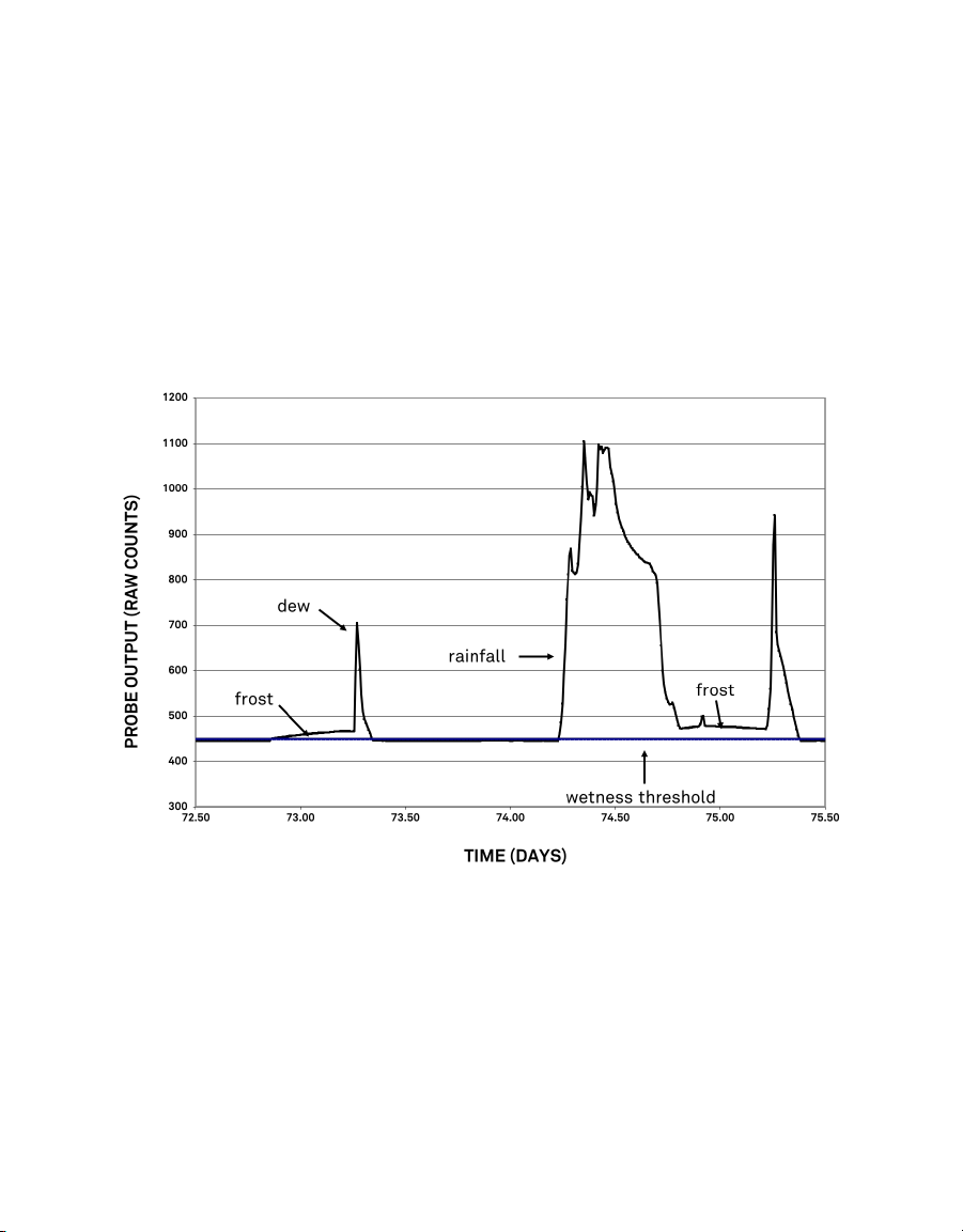
• Column 3: The final reading in raw counts of the PHYTOS 31 during the wake interval.
For example, if a 30-min wake interval has been chosen, the number in column 3 is the
output in raw counts from the PHYTOS 31 during the last minute of that 30-min period.
This data column can be used in the event of an extremely dirty PHYTOS 31, which may
force the dry output higher than 460 raw counts. In this case, the user can identify a new
wetness threshold from the time series data and calculate wetness duration from the
new threshold until the sensor can be cleaned (Section2.3.2). The data in this column
only gives a wetness reading every wake interval (typically 30 min or more), instead of the
1-min wetness resolution available in column 1 and 2. This column can also be used for
understanding the phase of the water, as shown in Figure5, as well as the amount of water
(as discussed in Predicting the amount of water on the surface of the PHYTOS 31 dielectric
leaf wetness sensor).
Em50 data loggers provide an unprocessed Excel file format with three columns of data for
each PHYTOS 31 port.
• Column 1: The cumulative number of minutes that the PHYTOS 31 output has been over
450 raw counts since the Em50 data were last erased or the accumulator has rolled over.
The accumulator has a maximum of 2,048 min (1.42 days) of wetness. If the cumulative
wetness duration exceeds this window (which likely happens often), then the accumulator
resets to 0 and begins accumulating again.
• Column 2: The cumulative number of minutes that the PHYTOS 31 output has been over
460 raw counts since the Em50 data were last erased or the accumulator has rolled over.
The accumulator rolls over to 0 after 2,048 min of wetness.
• Column 3: The final reading in raw counts of the PHYTOS 31 during the wake interval.
2.3.2 UNDERSTANDING DATA FROM OTHER DATA LOGGERS
With non-METER data loggers, the user needs to establish a wetness threshold for their
system. The dry output of the PHYTOS 31 varies with excitation voltage (note that the
acceptable excitation voltage range is 2.5 to 5.0 V). The PHYTOS 31 dry output is easily