manuals.online logo
Brands
  1. Home
  2. •
  3. Brands
  4. •
  5. Bosch
  6. •
  7. Security Sensor
  8. •
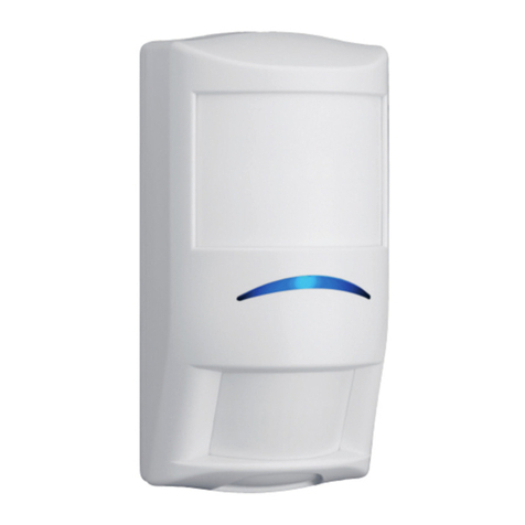
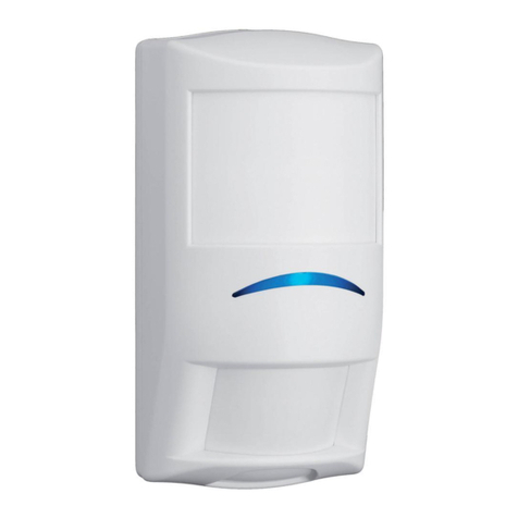
  9. Bosch DS840 User manual

Bosch DS840 User manual

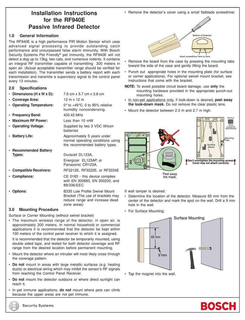
Installation Instructions
DS825, DS825T, DS840, DS840T
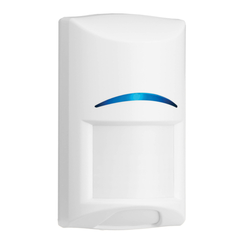
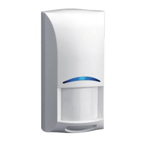
TriTechPIR/Microwave Intrusion Detectors
1.0 General Information
The DS825 Series and DS840 Series are microprocessor-based
TriTech Passive Infrared/MicrowaveIntrusionDetectorsthatprovide
immunity to false alarms caused by pets [a dog up to 100 lbs.
(45 kg) or up to 10 cats, and other small animals such as birds
and rodents]. Patented Passive Infrared and Microwave signal
processing provides excellent catch performance with freedom
from false alarms.
2.0 Specifications
•Input Power: 6 to 15 VDC, 15 mA DC nominal (up to
35 mA DC during walk testing).
•Standby Power: No internal standby battery. Connect to
DCpowersourcescapable ofsupplying
standby power. For each hour of
standbytime needed, 15 mAh are
required. For UL Listed Requirements,
four hours (60 mAh) are required.
•Alarm Relay: Silent operating Normally Closed reed
relay. Contacts rated 3 W, 125 mA,
28 VDC maximum for DC resistive
loads; and protected by a 4.7 Ω,1/2 W
resistor in the common “C” leg of the
relay. Do not use with capacitive or
inductive loads.
•Temperature: -40°F to +120°F (-40°C to +49°C). For
UL Certificated Installations, the
temperature range is +32°F to +120°F
(0°C to +49°C).
•Microwave Frequency:
DS825(T)/DS840(T): 10.525 GHz (UL Listed)
DS825TA/DS840TA: 10.687 GHz (Exportonly, not ULListed)
DS825TB/DS840TB: 9.9 GHz (Export only, not UL Listed)
•Coverage:
DS825 Series: 25 ft. x 25 ft. (8 m x 8 m)
DS840 Series: 40 ft. x 40 ft. (12 m x 12 m)
•Internal Pointability: +1° to –18° Vertical.
•Optional Tamper: The DS825T, DS825TA, DS825TB,
DS840T, DS840TA, and DS840TB
havea Normally Closed(with cover on)
tamper switch. Contacts rated at
28 VDC, 125 mA max. Connect the
tamper circuit to a 24-hour protection
circuit.
•Options: B335Low Profile SwivelMount Bracket
and B338 Ceiling Mount Bracket. (The
use of brackets may reduce range and
increase dead zone areas.)
• Reading Bosch Security Systems, Inc. Product Date Codes
For Product Date Code information, refer to the Bosch Security
Systems, Inc. Web site at: http://www.boschsecurity.com/datecodes/
•Compliance: This device complies with Part 15 of the FCC
Rules and with RSS-210 of Industry and Science Canada.
Operation is subject to the following two conditions:
(1) this device may not cause harmful
interference, and (2) this device must accept any
interference received, including interference that may cause
undesirable operation.
Changesor modifications not expressly approvedby Bosch Security
Systems can void the user's authority to operate the equipment.
3.0 Mounting
3.1 Mounting Considerations
•Neverinstallthe detectorin anenvironmentthat causesa constant
alarm in one technology; it should never be left to operate with
the tri-color LED in a constant green, yellow, or red condition. A
detector with one technology in constant alarm, will cause an
alarm output whenever the other technology alarms. Good
installationsstart with the LED OFF when thereisno targetmotion.
The best installations will have background noise voltages below
recommended limits.
• Point the unit away from outside traffic (e.g. roads, alleys, and
parking lots).
NOTE: Microwave energy will pass through glass and most
common non-metallic construction walls.
• Avoid direct or indirect sunlight.
• Pointtheunit awayfrom glassexposed totheoutdoors andobjects
that may change temperature rapidly.
NOTE: The PIR detector will react to objects rapidly changing
temperature within its field-of-view.
• Eliminate interference from nearby outside sources.
• Avoid installations where rotating machines (e.g. ceiling fans) are
normally in operation within the coverage pattern.
• Select a location likely to intercept an intruder moving across
the coverage pattern.
• The surface should be solid and vibration-free.
• Mounting height range is 6 to 8 ft. (1.8 to 2.4 m). The
recommended height is 7.5 ft. (2.3 m). Mounting height for Pet
Applications is 6.5 ft. (2 meters).
3.2 Mounting the Detector
• Remove the cover by inserting a thin flathead screwdriver into
the locking tab hole at the bottom front of the detector, pressing
in, and pulling the cover up and forward.
NOTE: Mount the unit with the terminal block up.
• Remove the circuit board from the base by pulling outward slightly
on one of the Circuit Board Locking Tabs (see Figure A).
Terminal
Block
LED
LED Jumper Microwave
Adjustment
Tamper
Terminals
Mirror
Assembly
Cable Knockout
Circuit Board
Locking Tab
(One on
Each Side)
Corner
Mounting
Holes (2)
Surface
Mounting
Holes (4)
Bracket Mounting
Hole Mirror
Tracks (2)
Circuit Board
Retainer Tabs (2)
Rear enclosure and mounting holes
Wiring
Knockouts
Figure A - Location of Features
• Remove the mirror.
Page 2 © 2011 Bosch Security Systems, Inc. DS825-825T-840-840T Installation Instructions
• Break away the Cable Knockout wire entrance.
• Open two holes for surface or corner mounting (See Figure A).
• Mark the location for the mounting screws.
- Use the enclosure as a template.
- Pre-start the mounting screws.
• Route wiring as necessary. Route to the rear of the base and
through the wire entrance. Make sure all wiring is unpowered
before routing.
• Securely attach the base to the mounting surface.
• Return the circuit board to the base.
• Install the mirror.
4.0 Wiring
Apply power ONLY after all connections have been
made and inspected. Do NOT coil excess wiring
inside the detector.
• Terminals (–) & (+): Power limits are 6 to 15
VDC. Use no smaller than #22 AWG (0.8 mm)
wire pair between the detector and the power
source.
• Terminals C & NC: Alarm relay (reed) contacts.
Do not use with capacitive or inductive loads.
• Tamper contacts: "T" Models only.
Plug the wire entrance hole with the foam plug
providedafter all wiring connectionshave been made.
6.0 LED Operation
The detector uses a tricolor LED to indicate the various alarm and
supervision trouble conditions that may exist. See the following chart:
Steady red
Steady yellow
Steady green
Flashing red
Flashing red (4 pulse sequence)
Unit alarm
Microwave activation (walk test)
PIR activation (walk test)
Warmup period after power-up
Microwave or PIR failure -
Replace Unit
LED Cause
If the detector experiences a Microwave or PIR self-test failure, it is in
need of replacement.
During walk testing, the LED will light for the first technology
(microwave or PIR) and then light red to indicate a detector alarm.
The LED will not indicate activation of the second technology by
lighting its color.
7.0 Feature Selection
•LED On/Off Pins: Placing the
jumper across the LED selection
pins allows operation of the
tricolor LED. If the tricolor LED
indication is not desired after
setup and walk tests are
completed,movethejumperfrom
across the LED selection pins.
Moving the jumper to the OFF
position does not prevent the
tricolor LED from indicating a
supervision trouble condition.
8.0 Setup and Walk Tests
• Select the vertical starting angle from the chart.
Height and desired Range
listed in feet (meters)
Mounting
Height DS825 DS840
-6°
-10°
-12°
-4°
-8°
-8°
25 (7.5) 40 (12)
6.5 (2.0)
7.5 (2.3)
8.5 (2.6)
Required Settings for Pet Applications
Broad Coverage Mirror
• The angle adjust markings are on the mirror. Slide the mirror
forward or back until the angle hash marks are in-line with the
markers on each side of the frame.
NOTE: See Section 11.0 for Pet Applications.
• Place the LED Jumper in the ON position.
•Wait at least two minutes, after applying power, to start walk
tests.
NOTE: During the warm-up period, the tricolor LED will flash red until
the unit has stabilized (approximately one to two minutes) and
has seen no movement for two seconds. When the LED stops
flashing, the detector is ready to be tested. With no motion in
the protection area, the LED should be OFF. If the LED is on,
recheck the protection area for
disturbances affecting the microwave
(yellow) or PIR (green) technologies.
Establishing PIR Pattern Coverage
• Turn the Microwave range adjust to minimum
and replace the cover.
• Walktestacross thepattern atitsfarthestedge,
then several times closer to the detector. Start
walking from outside of the intended protection area, and observe
the tricolor LED. The edge of the pattern is determined by the first
green, PIR activation of the LED (or the first red activation if the
yellow microwave LED activates first).
• Walktest from theopposite direction to determine both boundaries.
NOTE: The center of the pattern should be pointed toward the
center of the intended protection area.
• While standing 10 to 20 ft. (3 to 6 m) from the detector, slowly bring
your arm up and into the pattern to mark the lower boundary on
PIR alarm. Repeat from above for the upper boundary.
NOTE: The center of the pattern should not be tilted upward.
Ifthedesiredcoveragecannotbeachieved,try angling thecoverage
pattern up or down to assure the pattern is not aimed too high or
low.
Establishing Microwave Coverage
Wait one minute after removing/replacing the cover
so the microwave portion of the detector can settle.
Wait at least ten seconds between the following walk
testing procedures.
• The tricolor LED should be OFF before walk testing.
• Walk test across the pattern at the intended coverage’s farthest
end. Start walking from outside the intended protection area and
observe the tricolor LED. The edge of the microwave pattern is
determined by the first yellow, microwave activation of the LED (or
the first red activation if the green PIR LED activates first).
• If adequate range can not be reached, increase the Microwave
Range Adjust slightly. Continue walk testing (waiting one minute
after removing/replacing the cover) and adjusting the range until
the farthest edge of desired coverage has been accurately placed.
Minimum
MW Adjustment
+NC C
Alarm
Connect to a 24-hour
Protection Circuit
Cover
Off
Edge of
Circuit Board
LED
Pins
Program Plug
in the
OFF Position
LED
LED ON/OFF JUMPER PLACEMENTS
Edge of
Circuit Board
LED
Pins
Program Plug
in the
ON Position
LED
DS825-825T-840-840T Installation Instructions © 2011 Bosch Security Systems, Inc. Page 3
Do not adjust the microwave range higher than
required. Doing so will enable the detector to catch
movement outside of the intended coverage pattern.
• Walk test the unit from all directions to determine all the pattern
boundaries.
Establishing Detector Coverage
• The tricolor LED should be OFF before walk testing.
• Walk test the unit from all directions to determine the detection
boundaries. A detector alarm is signaled by the first red activation
of the tricolor LED after an initial green or yellow activation.
9.0 Supervision Features
The supervision features function as follows:
•PIR/Microwave: The complete circuit operation of these
subsystems is checked approximately every six hours. If the PIR or
microwavesubsystem fails, the tricolor LED willflash red four times
per cycle and the unit should be replaced.
•Default: The detector will default to PIR technology protection if
the microwave subsystem fails.
10.0 Other Information
Maintenance: At least once a year, the range and coverage should
be verified. To ensure continual daily operation, the end user should
be instructed to walk through the far end of the coverage pattern.
This ensures an alarm output prior to arming the system.
Pattern Masking: The PIR coverage pattern may be masked using
masking tape or electrical tape on the inside of the mirror.
Many adhesives will either destroy the mirror surface
or leave enough residue behind to reduce coverage
performance. Be sure to clean the mirror surface with
a mild window cleaning solution after masking
removal.
NOTE: Masking only eliminates the PIR portion of the coverage
and has no affect on the microwave pattern.
11.0 Special Instructions for Installations
Containing Pets
The DS825, DS825T, DS840 and DS840T detectors will provide
reasonableprotection from nuisancealarms caused bythe following
sources:
• One dog up to 100 pounds (45 kg) • Up to 10 cats
• Multiple small rodents, such as rats • Random flying birds
To take full advantage of the detector's Signature Recognition
Technology, the following guidelines should be followed:
• Do not remove the Pet Filter from the mirror.
NOTE: The Pet Filter is not a mirror mask. Use only the supplied
filter for pet applications.
• Mount the detector 6.5 ft. (2 m) high and adjust the Mirror angle
as shown in the chart in Section 8.0.
• Mount where the animals can not come within 6 ft. (1.8 m) of the
detector by climbing on furniture or other objects.
• Adjust the microwave range for the minimum acceptable
coverage for the room in which the detector is installed.
NOTE: Pet avoidance is only available when using the lens
provided with the detector. This pet nuisance protection
has not been verified by Underwriters Laboratories, Inc.
JKLMN
O
P
Q+2 0
-8
-16
+2
0
-8
-16
ABCDEFGHI
Mirror Segment to
Pattern Reference
Do not remove the
Pet Filter for pet
applications.
For non-pet
applications, the
Pet Filter must be
removed.
Pet Filter
2/11
DS825-825T-840-840T Installation Instructions
P/N: F01U034969-11 Page 4
12.0 Coverage Patterns
The protected coverage area is where the microwave and PIR patterns overlap. Microwave
PIR
0Meters
0Feet 40
12
0
F
e
e
t
20
20
Top
DS840 Coverage
6
6
M
e
t
e
r
s
0
H
I
F
G
E
C
D
A
B
012
40
Meter
0
10
F
e
e
t
Side View
0Feet
M
e
t
e
r
s
0
3
Mirror adjusted to -4°
2
6.5
L
K
J
M
N
P
Q
O
08
Side View
Mirror adjusted to -6° 25
Meter
0
10
F
e
e
t0Feet
M
e
t
e
r
s
0
3
6.5 2
25
0Meters
0Feet
8
0
F
e
e
t
15
Top
DS825 Coverage
4
4
M
e
t
e
r
s
0
15
D
F
I
H
E
G
C
A
B
J
K
L
M
N
O
P
Q
© 2011 Bosch Security Systems, Inc.
130 Perinton Parkway, Fairport, New York 14450
www.boschsecurity.com

This manual suits for next models

3

Other Bosch Security Sensor manuals

Bosch RADION PIR C User manual

Bosch

Bosch RADION PIR C User manual

Bosch DS938Z Series User manual

Bosch

Bosch DS938Z Series User manual

Bosch D-tect 120 Quick guide

Bosch

Bosch D-tect 120 Quick guide

Bosch RADION contact SM User manual

Bosch

Bosch RADION contact SM User manual

Bosch MX938I User manual

Bosch

Bosch MX938I User manual

Bosch ISC-BDL2-WP12 User manual

Bosch

Bosch ISC-BDL2-WP12 User manual

Bosch Blue Line P1 User manual

Bosch

Bosch Blue Line P1 User manual

Bosch DS939 User manual

Bosch

Bosch DS939 User manual

Bosch DS840LSN User manual

Bosch

Bosch DS840LSN User manual

Bosch FCS-LWM-1 User manual

Bosch

Bosch FCS-LWM-1 User manual

Bosch Truvo User manual

Bosch

Bosch Truvo User manual

Bosch ISN?SM?80 User manual

Bosch

Bosch ISN?SM?80 User manual

Bosch DS778 User manual

Bosch

Bosch DS778 User manual

Bosch IR LD 1.0 User manual

Bosch

Bosch IR LD 1.0 User manual

Bosch RF940E Operation and maintenance manual

Bosch

Bosch RF940E Operation and maintenance manual

Bosch Photobeam 5000 Operating instructions

Bosch

Bosch Photobeam 5000 Operating instructions

Bosch D-tect 120 Professional User manual

Bosch

Bosch D-tect 120 Professional User manual

Bosch DS9370 TriTech User manual

Bosch

Bosch DS9370 TriTech User manual

Bosch Blue Line Q1 User manual

Bosch

Bosch Blue Line Q1 User manual

Bosch SF8172 User manual

Bosch

Bosch SF8172 User manual

Bosch ISW-ZPR1-WP13 User manual

Bosch

Bosch ISW-ZPR1-WP13 User manual

Bosch D-tect 150 User manual

Bosch

Bosch D-tect 150 User manual

Bosch Analog Detector Series Operating instructions

Bosch

Bosch Analog Detector Series Operating instructions

Bosch ISC-PPR1-W16G User manual

Bosch

Bosch ISC-PPR1-W16G User manual

Popular Security Sensor manuals by other brands

Lyyt 154.840UK quick start guide

Lyyt

Lyyt 154.840UK quick start guide

Niko 352-0273 Series manual

Niko

Niko 352-0273 Series manual

Lighting Technologies IS 770 quick start guide

Lighting Technologies

Lighting Technologies IS 770 quick start guide

Banner PVS28 Series instruction manual

Banner

Banner PVS28 Series instruction manual

Compur Statox 501 IR LC Brochure & specs

Compur

Compur Statox 501 IR LC Brochure & specs

ipf electronic UY000001 instruction manual

ipf electronic

ipf electronic UY000001 instruction manual

Wizmart NB326-S Installation Wiring Diagram

Wizmart

Wizmart NB326-S Installation Wiring Diagram

Interlogix AS520 Series quick start guide

Interlogix

Interlogix AS520 Series quick start guide

EMX Industries, Inc. ULT-PLG ULTRALOOP operating instructions

EMX Industries, Inc.

EMX Industries, Inc. ULT-PLG ULTRALOOP operating instructions

BorMann BDM5000 instruction manual

BorMann

BorMann BDM5000 instruction manual

Weco G5 Series user manual

Weco

Weco G5 Series user manual

Eaton Powerware Series user guide

Eaton

Eaton Powerware Series user guide

AJAX FireProtect 2 Jeweller manual

AJAX

AJAX FireProtect 2 Jeweller manual

Texecom Impaq SC-W installation manual

Texecom

Texecom Impaq SC-W installation manual

Greifzug blocstop BSO Series Operation and installation

Greifzug

Greifzug blocstop BSO Series Operation and installation

Ocean Signal rescureME MOB1 user manual

Ocean Signal

Ocean Signal rescureME MOB1 user manual

SICK Prime KTX-WP92142242ZZZZ manual

SICK

SICK Prime KTX-WP92142242ZZZZ manual

AMC SR135 quick start guide

AMC

AMC SR135 quick start guide

manuals.online logo
manuals.online logoBrands
  • About & Mission
  • Contact us
  • Privacy Policy
  • Terms and Conditions

Copyright 2025 Manuals.Online. All Rights Reserved.