manuals.online logo
Brands
  1. Home
  2. •
  3. Brands
  4. •
  5. Meyer
  6. •
  7. Lantern
  8. •
  9. Meyer Monospot 3 User manual

Meyer Monospot 3 User manual

159 0159 –0518
Monospot 3
Anbauleuchte
Luminaire
Schutzart –Protection IP 65
Schutzklasse –Safety Class I
MONTAGE
ANLEITUNG
MOUNTING
INSTRUCTIONS
WILLY MEYER & SOHN GMBH &CO.KG
LICHTECHNISCHE SPEZIALFARIK
Stemmessiepener Weg 5 • D-58675 Hemer
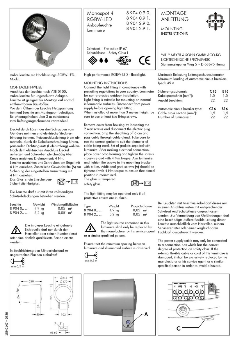
Anbauleuchte mit Hochleistungs-LED Modul.
MONTAGEHINWEISE
Anschluß der Leuchte nach VDE 0100.
Anbauleuchte für ungeschützte Anlagen.
Leuchte ist geeignet für Montage auf normal
entflammbaren Baustoffen.
Vor dem Öffnen der Leuchte Netzspannung
trennen! Leuchte am Montageort befestigen.
Bei Montagehöhen über 3 m mindestens
zwei Befestigungsschrauben verwenden!
Deckel durch Lösen der drei Schrauben vom
Gehäuse nehmen und elektrische. Steckver-
bindung trennen. Netzanschlußleitung 6 cm ab-
manteln, durch die Kabelverschraubung führen,
passenden Dichtungssatz (Lieferumfang) wählen.
Nach dem elektrischen Anschluss Deckel
aufsetzen und Schrauben gleichmäßig über
Kreuz anziehen: Drehmoment: 4 Nm.
Leuchte ausrichten und Schrauben am Bügel
ebenfalls mit 5 Nm anziehen. Zusätzliche
Gewindestifte Azur Sicherung der eingestellten
Ausrichtung mit 4 Nm anziehen. Das Glas ist ein
Einscheiben-
Sicherheits-Hartglas.
Die Leuchte darf nur mit ihren vollständigen
Schutzabdeckungen betrieben werden.
Leuchte Gewicht Windangriffsfläche
8 903 0.. ... 3,1 kg 0,049 m²
8 903 2.. ... 3,3 kg 0,049 m²
Die in dieser Leuchte eingebaute
Lichtquelle darf nur durch den
Hersteller oder seinen Kundendienst
oder eine ähnlich qualifizierte Person ersetzt
werden.
In Strahlrichtung den Mindestabstand zu
angestrahlten Flächen einhalten!
High performance LED - floodlight.
MOUNTING INSTRUCTIONS
Connect the light fitting in compliance with
prevailing regulations in your country. Luminaire
for non-protected outdoor installation.
Light fitting is suitable for mounting on normal
inflammable surfaces. Disconnect from power
supply before opening light fitting.
When installed at more than 3 metres height, be
sure to use at least two fixing screws.
Remove cover from housing by loosening the
2 rear screws and disconnect the electrik plug
connection. Remove the sheathing from the last
6 cm of cable and pass cable through cable
gland. Take care to use the correct gasket to suit
the diameter of cable being used. Set of gaskets
supplied with luminaire. After making electrical
connection, place cover onto housing and
tighten the screws crosswise and with 4 Nm
torque. Aim luminaire and tighten the screws in
the mounting bracket with 5 Nm. Additional grub
screws (A) should be tightened with 4 Nm torque
to ensure that aimed position is maintained.
The glass is tempered
safety glass.
The light fitting may be operated only if all
protective covers are in place.
Type Weight Projected area
8 903 0.. ... 3,1 kg 0,049 m²
8 903 2.. ... 3,3 kg 0,049 m²
The light source contained in this
luminaire shall only be replaced by
the manufacturer or his service agent
or a similar qualified person.
Ensure that the minimum spacing between
luminaire and illuminated surface is abserved.
Maximale Belastung Leitungsschutzautomaten
Maximum loading of automatic circuit breakers
Ipeak 20 A 400 μs
Sicherungsautomat: C16 B16
Kabelquerschnitt [mm²]: 1,5 1,5
Anzahl Leuchten: 25 15
automatic circuit breaker type: C16 B16
cable cross section [mm²]: 1,5 1,5
number of luminaires: 25 15
Die DALI- und die 1-10 V Steuerleitung sind
gegenüber der Netzleitung basisisoliert.
DALI dimmbare Leuchten:
Steueradern für die Dimmung gemäß Klemmen-
beschriftung anschließen.
1-10 V dimmbare Leuchten:
Steueradern für die Dimmung gemäß Klemmen-
beschriftung anschließen.
Auf Polarität achten!
The DALI- and 1-10 V control wire are equipped
with basic insulation against the power supply.
DALI dimmable luminaire:
Connect the wires for the dimming system
according to the marking on the terminal block.
1-10 V dimmable luminaire:
Connect the wires for the dimming system
according to the marking on the terminal block.
Ensure correct polarity!
8 903 0.. 0..
8 903 0.. 1..
8 903 0.. 2..
8 903 2.. 0..
8 903 2.. 1..
8 903 2.. 2..
159 0159 –0518
Mastleuchte mit Hochleistungs-LED Modul.
Zusätzliche Montagehinweise Mastleuchte
Leuchte ausrichten und Schrauben am Gelenk mit
5 Nm anziehen. Zusätzliche Gewindestifte (A) zur
Sicherung der eingestellten Ausrichtung mit 4 Nm
anziehen.
Durch lösen der 3 Schrauben (B) kann die
Leuchte an der Mastbefestigung um 360° gedreht
werden.
Die Netzanschlussleitung durch die
Mastbefestigung (Ø13,5 mm) in den Mast
führen.
Pole high performance LED - floodlight.
Extra mounting instruction pole luminaire
Aim luminaire and tighten the screws in the
mounting bracket with 5 Nm. Additional grub
screws (A) should be tightened with 4 Nm torque
to ensure that aimed position is maintained.
By resolving the 3 screws (B) the luminaire can
be the turned 360°.
Push the cable through the hole (Ø13,5 mm) of
the pole fixation.
Bei Leuchten mit Anschlusskabel darf dieses nur
in einen Anschlusskasten mit entsprechender
Schutzart und Schutzklasse angeschlossen
werden. Zur Vermeidung von Gefährdungen darf
eine beschädigte äußere flexible Leitung dieser
Leuchte ausschließlich vom Hersteller, seinem
Servicevertreter oder einer vergleichbaren
Fachkraft ausgetauscht werden.
The power supply cable may only be connected
to a connection box witch has the correct degree
of protection and safety class. If the external
flexible cable or cord of this luminaire is
damaged, it shall be exclusively replaced by the
manufacturer or his service agent or a similar
qualified person in order to avoid a hazard.

Other Meyer Lantern manuals

Meyer 8 904 0.9 0 Series User manual

Meyer

Meyer 8 904 0.9 0 Series User manual

Meyer Nightspot B LED Street Optik User manual

Meyer

Meyer Nightspot B LED Street Optik User manual

Meyer Nightspot BRGBW-LED User manual

Meyer

Meyer Nightspot BRGBW-LED User manual

Meyer Nightspot B 8 987 0 Series User manual

Meyer

Meyer Nightspot B 8 987 0 Series User manual

Meyer Nightline A User manual

Meyer

Meyer Nightline A User manual

Popular Lantern manuals by other brands

esotec Pro RGB instruction manual

esotec

esotec Pro RGB instruction manual

Sealite SL-07LB Installation & service manual

Sealite

Sealite SL-07LB Installation & service manual

Perel EFCL01 Guide

Perel

Perel EFCL01 Guide

olympia electronics GR-490/ADR manual

olympia electronics

olympia electronics GR-490/ADR manual

PROSTO LRFS-28C001-W/BK instruction manual

PROSTO

PROSTO LRFS-28C001-W/BK instruction manual

Awex LOVATO P 3 Assembly instructions

Awex

Awex LOVATO P 3 Assembly instructions

WE-EF CFS500 Series Installation and maintenance instructions

WE-EF

WE-EF CFS500 Series Installation and maintenance instructions

Fusion 30117 Assembly instructions

Fusion

Fusion 30117 Assembly instructions

Vector SPORT SPOT LANTERN COMBO User's manual & warranty information

Vector

Vector SPORT SPOT LANTERN COMBO User's manual & warranty information

Emos ZM5121 manual

Emos

Emos ZM5121 manual

ETC Source Four jr Assembly guide

ETC

ETC Source Four jr Assembly guide

Eaton Champ VMVL Series Installation & maintenance information

Eaton

Eaton Champ VMVL Series Installation & maintenance information

Cooper Crouse-Hinds ILLUMINATOR EVFT Series Installation & maintenance information

Cooper Crouse-Hinds

Cooper Crouse-Hinds ILLUMINATOR EVFT Series Installation & maintenance information

Maximex 9933161500 Instructions for use

Maximex

Maximex 9933161500 Instructions for use

MELINERA 298663 instructions

MELINERA

MELINERA 298663 instructions

Coleman 286A Instructions for use

Coleman

Coleman 286A Instructions for use

Chalmit NexLED Installation, operation and maintenance instructions

Chalmit

Chalmit NexLED Installation, operation and maintenance instructions

MEDC FL11 Technical manual

MEDC

MEDC FL11 Technical manual

manuals.online logo
manuals.online logoBrands
  • About & Mission
  • Contact us
  • Privacy Policy
  • Terms and Conditions

Copyright 2025 Manuals.Online. All Rights Reserved.