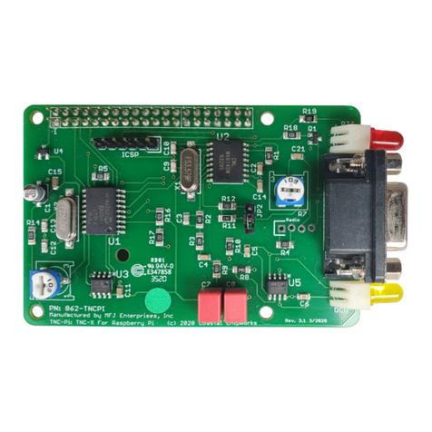
. Carefully remove all IC chips from the TNC. Make note as to the orientation
of each IC in their respective IC sockets and which sockets the ICs came out
of. Be careful not to bend any of the pins of the ICs. IMPORTANT!
3. Carefully re-insert one IC at a time into its respective socket and recheck the
+5 volts DC. If any IC causes the +5 volts DC to drop, then the IC that caus-
es the voltage drop is your defective part. Be sure to check all IC chips, be-
cause you could have more than one defective part. Call the MFJ Service
Dept. for a replacement part.
Testing Receive
Hook up a receiver audio source to the receive pins on the board (or the mono
jack if you are using the enclosure). Make sure audio goes to the positive pin.
Make sure the squelch is left open. When a data packet is received, you should
see the yellow LED light briefly and go out. Even when no data is being received
it is normal for the yellow LED to flicker. However, it should come solidly on when
a packet is received. Assuming that this checks out, run a serial program of some
kind on your PC, set the baud rate to whatever baud rate you specified with JP1
and JP . Confirm that you are receiving data (note, this will be raw KISS frames
so much of it may look like garbage, but you should see some recognizable data).
Note that if you are using the USB option, you must the USB drivers loaded on
your computer.
If you do not see the yellow light come on, first confirm that audio is getting to
the TNC (a scope or a small headphone may be useful for this). If it is, verify that
audio is coming out of Pin 6 of U4. Assuming this is working, if you have a scope
or frequency counter, measure the frequency on Pin 1 of U1. It should read about
3.57 MHz. While you are at it, check Pin 16 of U3. It should read about 0 MHz.
If at any point you don’t get the measurement you expect, carefully check the
solder joints in that part of the board. If the yellow light comes on but you see no
data on your PC, start at Pin 8 of U3 and trace the data signal to header Pin 1, to
header Pin and on to Pin 10 of U5. It should come out at Pin 7 of U5.
Next check out the transmit chain. The TXDelay is set by R13. Start by setting it
at about halfway (which will correspond to a TXDelay of about 40 ms (or a set-
ting of 5 on most TNC’s). At this point you need to be running a program on
your PC that supports KISS mode. The TNC-X webpage (www.tnc-x.com/docu-
mentation.htm) has a program called TXTest, which is a very simple program that
can be used to test your transmit chain.


