Circontrol CCL-PT3 SMART User manual

INSTALLATION MANUAL
CCL-PT3 SMART
CCL-PT3 SMART 3G
SEMI FAST CHARGE STATION FOR
ELECTRIC VEHICLES

SMART POST PT3 Installation manual
This document is copyrighted, 2014 by Circontrol, S.A. All rights are reserved.
Circontrol, S.A. reserves the right to make improvements to the products
described in this manual at any time without notice.
No part of this manual may be reproduced, copied, translated or transmitted in
any form or by any means without the prior written permission of the original
manufacturer. Information provided in this manual is intended to be accurate
and reliable. However, the original manufacturer assumes no responsibility for
its use, or for any infringements upon the rights of third parties that may result
from its use.
All other product names or trademarks are properties of their respective
owners.
V1.5, April edition 2014

CIRCONTROL, S.A. –Innovació, 3 –08232 –Viladecavalls (Barcelona)
Tel.: +34 937 362 940 –Fax: +34 937 362 941 1
INSTALLATION MANUAL –CCL-PT3 SMART & CCL-PT3 SMART 3G–
CONTENTS
1PREFACE ............................................................................................................................. 2
2IMPORTANT SAFETY INSTRUCTIONS..............................................................................3
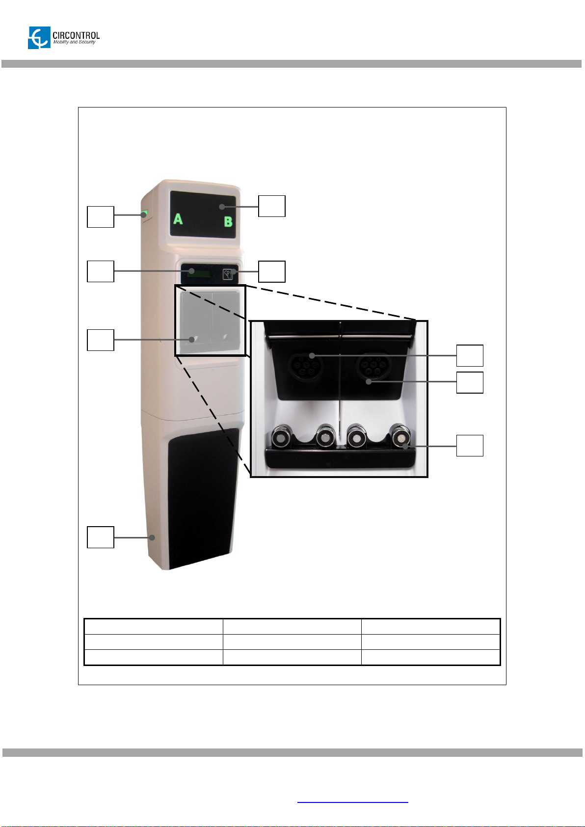
3PRODUCT OVERVIEW ........................................................................................................4
4COMPONENT PARTS LOCATION......................................................................................5
5PRODUCT DIMENSIONS.....................................................................................................6
6INSTALLATION .................................................................................................................... 7
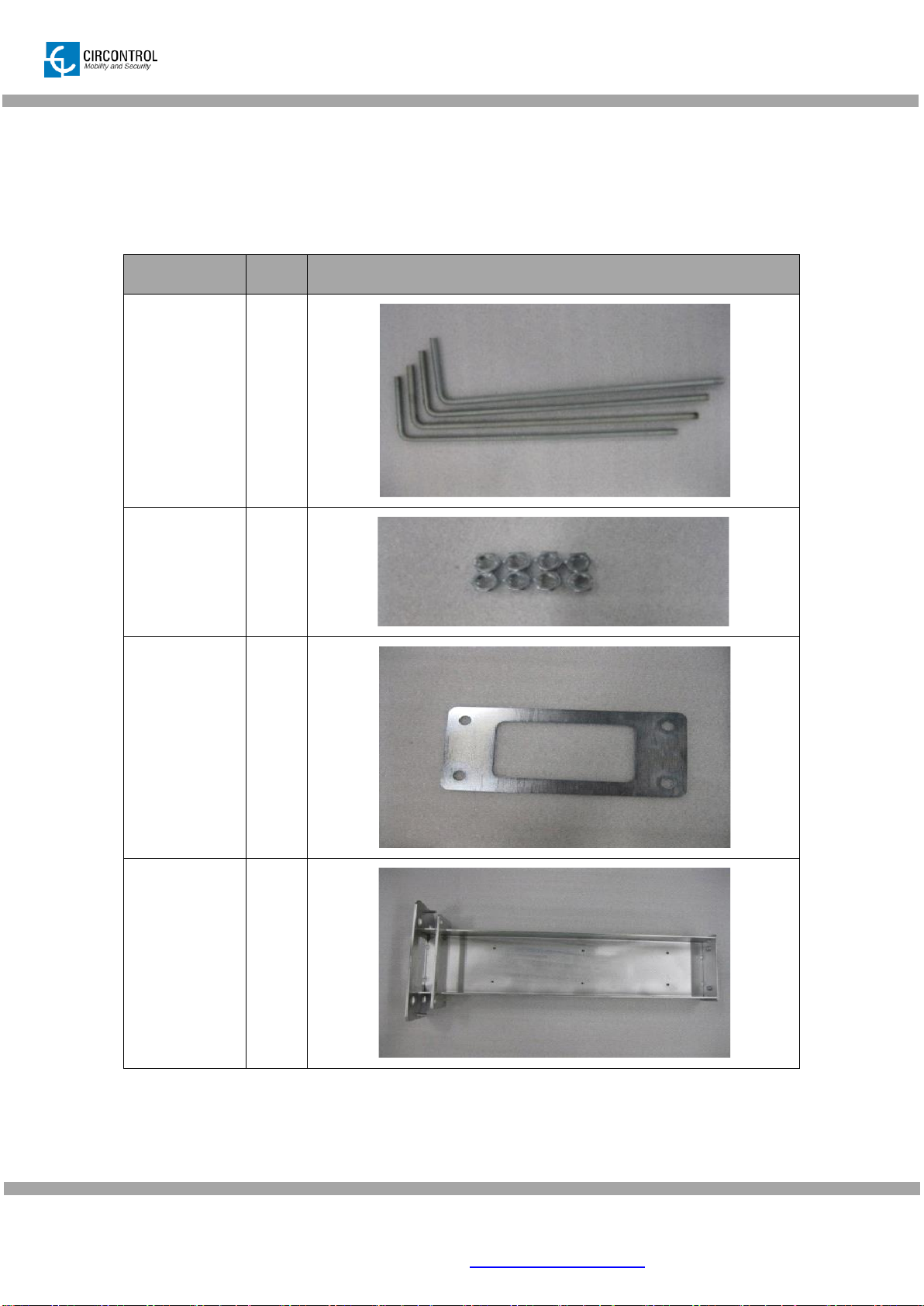
6.1 PREREQUISITES .........................................................................................................7
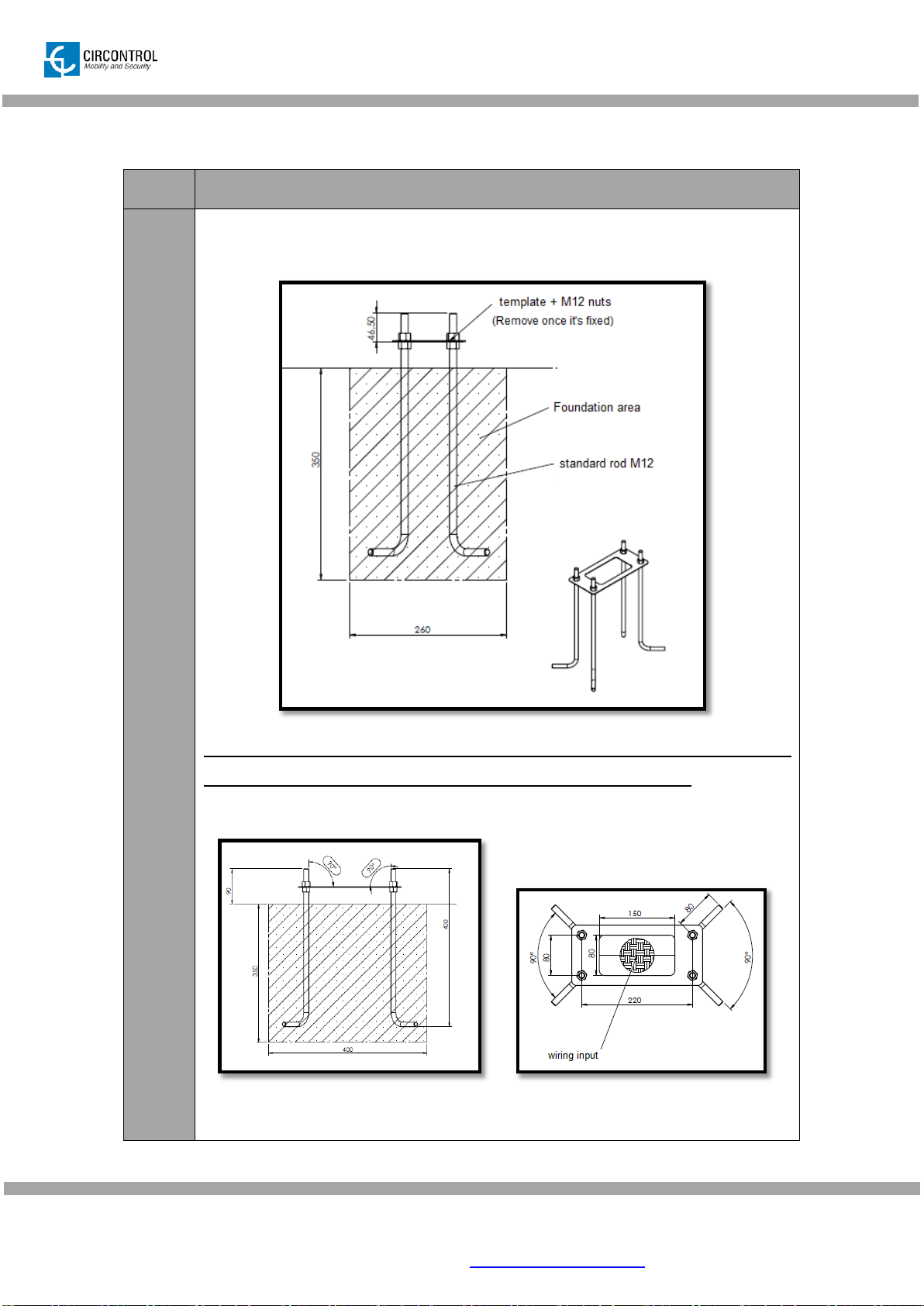
6.2 FOUNDATION DRAWING ............................................................................................8
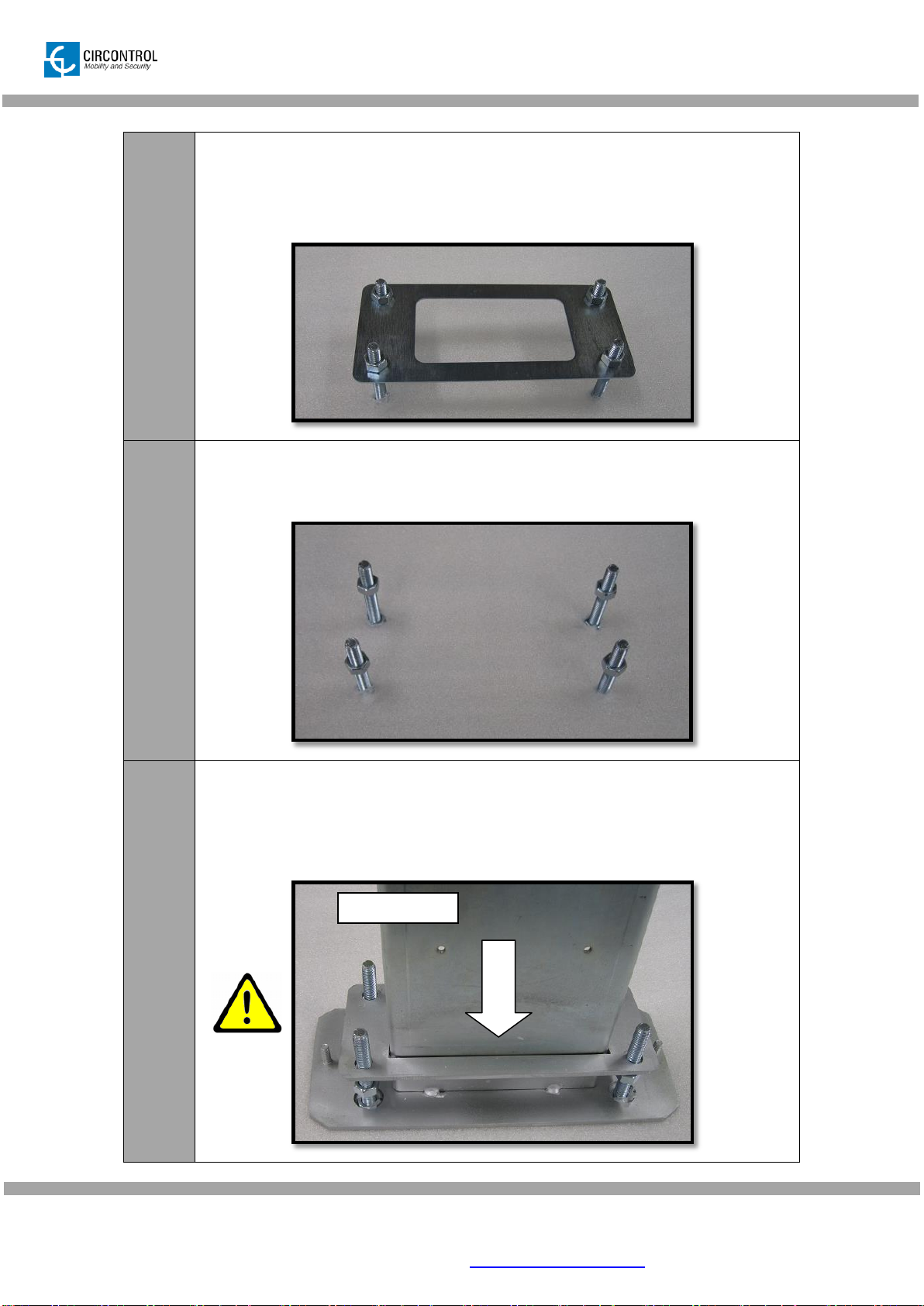
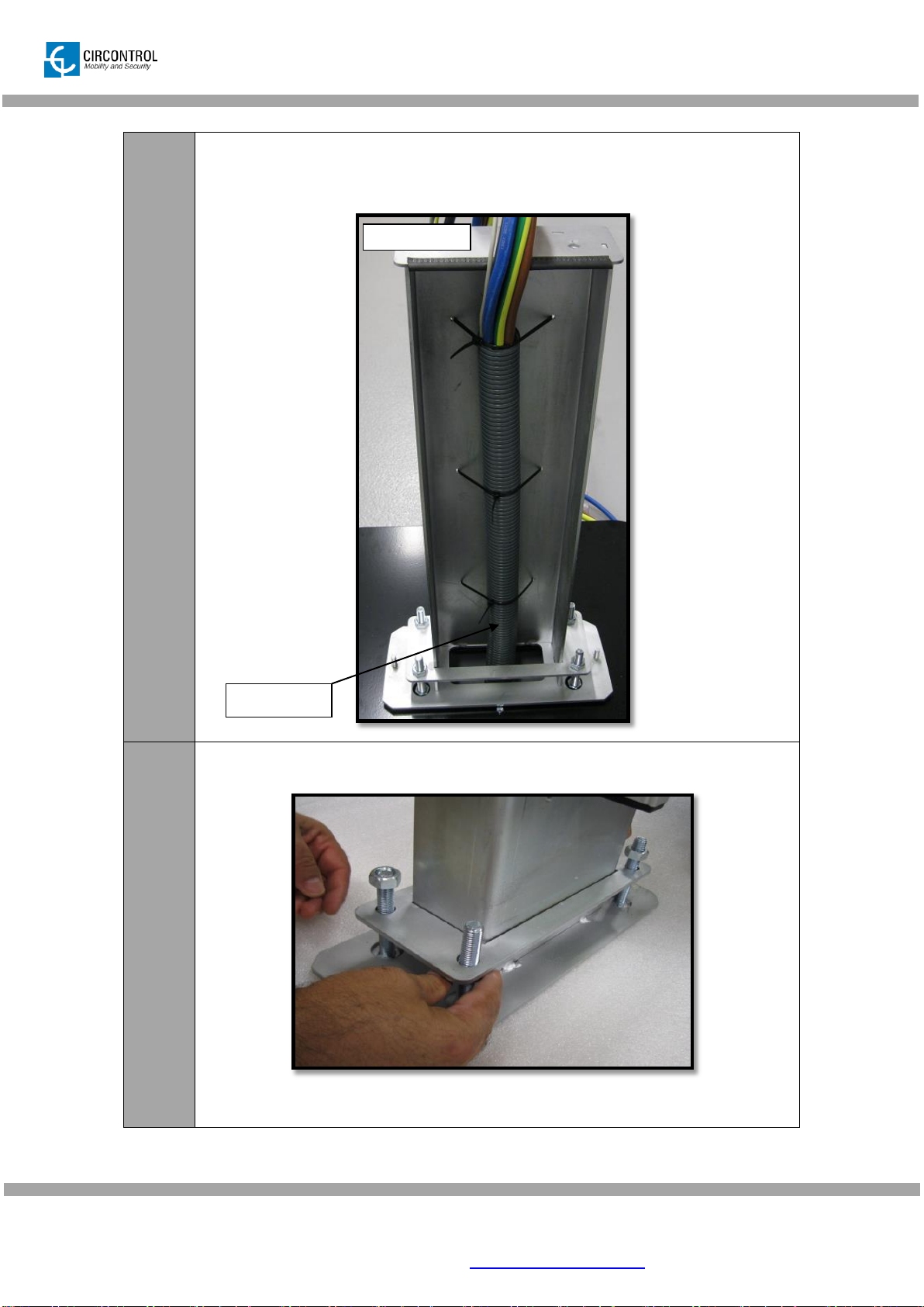
6.3 FOUNDATION PROCEDURE....................................................................................... 9
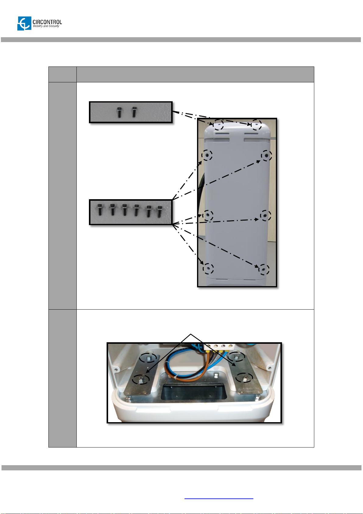
6.4 ASSEMBLY MAIN BODY ............................................................................................16
7INSERT THE SIM CARD (FOR 3G MODELS)...................................................................19
8ETHERNET CONNECTION................................................................................................ 21
9ELECTRICAL INSTALLATION .......................................................................................... 22
10 CLOSING THE UNIT........................................................................................................... 23
11 UNIT VERIFICATION..........................................................................................................24
12 TECHNICAL DATA............................................................................................................. 25

CIRCONTROL, S.A. –Innovació, 3 –08232 –Viladecavalls (Barcelona)
Tel.: +34 937 362 940 –Fax: +34 937 362 941 2
INSTALLATION MANUAL –CCL-PT3 SMART & CCL-PT3 SMART 3G–
1 PREFACE
THE FOLLOWING SYMBOLS ARE USED FOR
IMPORTANT SAFETY INFORMATION IN THIS
DOCUMENT
The unit must be disconnected from any power source before
performing any maintenance, repair or handling of any
equipment connections.
Do not modify the unit. If modified, CIRCONTROL will reject
all responsibility and the warranty will be void.
This manual provide commissioning information for SMART POST SERIES, which has
been designed and tested to allow electric vehicle charging, specified in IEC 61851.
This document has different sections where describes electrical components inside the
charge station and a step-by-step installation procedure.
Certification
Complies with IEC 61851, Electric vehicle conductive charging system (IEC
61851-1)
Complies with IEC 62196, Plugs, socket-outlets, vehicle couplers and vehicle
inlets -
Conductive charging system (IEC 62196-1 and IEC 62196-3).
RFID complies with ISO 14443A

CIRCONTROL, S.A. –Innovació, 3 –08232 –Viladecavalls (Barcelona)
Tel.: +34 937 362 940 –Fax: +34 937 362 941 3
INSTALLATION MANUAL –CCL-PT3 SMART & CCL-PT3 SMART 3G–
2 IMPORTANT SAFETY INSTRUCTIONS
Read all the instructions before using and install this product.
Do not use cables there are not in perfect conditions.
Do not use this unit for anything other than electric vehicle charging
Charging modes are expected in IEC 61851-1.
Do not modify this unit. If modified, CIRCONTROL will reject all
responsibility and the warranty will be void.
Comply strictly with current safety regulations according to your
country rules.
Do not make repairs or manipulations with the unit energised.
Only trained and qualified personnel should have access to low-
voltage electrical parts inside the device.
Check the installation annually by qualified technician.
Remove from service any item that has a fault that could be dangerous
for users (broken plugs, caps that don’t close...).
Use only Circontrol supplied spare parts.
Do not use this product if the enclosure or the EV connector is broken,
cracked, open, or shows any other indication of damage.

CIRCONTROL, S.A. –Innovació, 3 –08232 –Viladecavalls (Barcelona)
Tel.: +34 937 362 940 –Fax: +34 937 362 941 4
INSTALLATION MANUAL –CCL-PT3 SMART & CCL-PT3 SMART 3G–
3 PRODUCT OVERVIEW
1. Rear Beacons
2. Charge Status indicator
3. Liquid Cristal Display
4. RFID Reader
5. Vandal doors
6. Plug A –Type 2
7. Plug B –Type 2
8. Electromagnets
9. Base
8
4
3
1
5
9
6
7
2
9
2

CIRCONTROL, S.A. –Innovació, 3 –08232 –Viladecavalls (Barcelona)
Tel.: +34 937 362 940 –Fax: +34 937 362 941 5
INSTALLATION MANUAL –CCL-PT3 SMART & CCL-PT3 SMART 3G–
4 COMPONENT PARTS LOCATION
1. Rear Beacon Plug B (H1)
2. CCL1 Device (U1)
3. Plug A –Meter (AN1)
4. Plug B –Meter (AN2)
5. Plug A –Mode 3 (AM3-1)
6. Plug B –Mode 3 (AM3-2)
7. RFID Reader (B3)
8. LCD Display (H3)
9. Type 2 socket (B2)
10. Heater (R1)
11. MCB Power Supply (Q3)
12. WGS-20 (T3)
13. Power Supply (G1)
14. AC Power terminals
15. Thermostat (G3)
16. Tamper switch (S1)
17. Plug A –Contactor (K1)
18. Plug B –Contactor (K2)
19. Relay power supply (K3)
20. Plug A –MCB (Q1)
21. Plug B –MCB (Q2)
22. Type 2 socket (B1)
23. Plug A –Relay
electromagnet (K7)
24. Plug B –Relay
electromagnet Plug B (K8)
25. CBS-4C RCD (AF1)
26. Beacon led driver (X2.1)
27. Rear beacon Plug A (H2)
28. Beacon led driver
(X1.1)
1
2
4
5
6
7
9
12
13
16
20
21
22
23
24
25
27
17
18
3
19
14
8
10
11
26
28
15

CIRCONTROL, S.A. –Innovació, 3 –08232 –Viladecavalls (Barcelona)
Tel.: +34 937 362 940 –Fax: +34 937 362 941 7
INSTALLATION MANUAL –CCL-PT3 SMART & CCL-PT3 SMART 3G–
6 INSTALLATION
6.1 PREREQUISITES
Bellow material list is attached with the unit for foundation and installation purpose.
Material
Qty
Picture
“L Threaded
bar
4
M12 Nuts
8
Center
template
1
Main fixing
structure unit
1
Nº Qty Picture
1 4
2 8
3 1
4 1
Material
“L” threaded bar
M12 Nuts
Centering template
Main fixing structure unit
Nº Qty Picture
1 4
2 8
3 1
4 1
Material
“L” threaded bar
M12 Nuts
Centering template
Main fixing structure unit
Nº Qty Picture
1 4
2 8
3 1
4 1
Material
“L” threaded bar
M12 Nuts
Centering template
Main fixing structure unit
Nº Qty Picture
1 4
2 8
3 1
4 1
Material
“L” threaded bar
M12 Nuts
Centering template
Main fixing structure unit

CIRCONTROL, S.A. –Innovació, 3 –08232 –Viladecavalls (Barcelona)
Tel.: +34 937 362 940 –Fax: +34 937 362 941 9
INSTALLATION MANUAL –CCL-PT3 SMART & CCL-PT3 SMART 3G–
6.3 FOUNDATION PROCEDURE
STEP
ACTION
1
The four “L” threaded bars must be placed and cemented underground in
the foundation place as shows bellow figure.
Drawing foundation dimensions are minimum recommended to fix post
to the ground, please consider hardness ground conditions.

CIRCONTROL, S.A. –Innovació, 3 –08232 –Viladecavalls (Barcelona)
Tel.: +34 937 362 940 –Fax: +34 937 362 941 10
INSTALLATION MANUAL –CCL-PT3 SMART & CCL-PT3 SMART 3G–
2
Once the four “L” threaded bars are undergrounded, the metal template must
be mounted, as shown in the image, in order to get the bars completely
aligned.
3
When dry, remove the template, and keep the four nuts that must be
lowered close to the floor level.
4
Insert the main fixing structure through the lower holes.
ATTENTION!! : Be careful with the position of the base (BACK & FRONT)
due is not symmetrical.
FRONT VIEW

CIRCONTROL, S.A. –Innovació, 3 –08232 –Viladecavalls (Barcelona)
Tel.: +34 937 362 940 –Fax: +34 937 362 941 11
INSTALLATION MANUAL –CCL-PT3 SMART & CCL-PT3 SMART 3G–
5
Connections wires must be introduced and fixed as shown in the back view
image.
6
Adjust the lower four nuts, you can properly level the main structure.
BACK VIEW
Wire Input

CIRCONTROL, S.A. –Innovació, 3 –08232 –Viladecavalls (Barcelona)
Tel.: +34 937 362 940 –Fax: +34 937 362 941 12
INSTALLATION MANUAL –CCL-PT3 SMART & CCL-PT3 SMART 3G–
7
1. Tight strongly with the appropriate tools, the upper nuts.
2. Check main fixing structure unit has not inclination using a level tool.

CIRCONTROL, S.A. –Innovació, 3 –08232 –Viladecavalls (Barcelona)
Tel.: +34 937 362 940 –Fax: +34 937 362 941 14
INSTALLATION MANUAL –CCL-PT3 SMART & CCL-PT3 SMART 3G–
10
1. Insert the connection wires through supplied the metal plate.
2. Assembly metal plate screwing with 6 supplied screws and keep
original position for all screws.

CIRCONTROL, S.A. –Innovació, 3 –08232 –Viladecavalls (Barcelona)
Tel.: +34 937 362 940 –Fax: +34 937 362 941 16
INSTALLATION MANUAL –CCL-PT3 SMART & CCL-PT3 SMART 3G–
6.4 ASSEMBLY MAIN BODY
STEP
ACTION
1
After unpack main body, remove 8 screws from rear cover.
2
Assembly main body with two covers plates and the four M8 supplied screws
as shown below.
ATTENTION: Do not trap connection wires with main body.

CIRCONTROL, S.A. –Innovació, 3 –08232 –Viladecavalls (Barcelona)
Tel.: +34 937 362 940 –Fax: +34 937 362 941 17
INSTALLATION MANUAL –CCL-PT3 SMART & CCL-PT3 SMART 3G–
3
Install tamper switch and adjust its position with the two screws.
After assembly, check tamper position and adjust push button to position 1
Tamper possible positions
1. Maintenance position
2. Open cover (Alarm on)
3. Normal function
3 2 1

CIRCONTROL, S.A. –Innovació, 3 –08232 –Viladecavalls (Barcelona)
Tel.: +34 937 362 940 –Fax: +34 937 362 941 18
INSTALLATION MANUAL –CCL-PT3 SMART & CCL-PT3 SMART 3G–
4
The unit is ready to electrical connections described in section nº 8.
It is recommended to keep a distance of approximately 40cm of electric wires
before cutting.
5
Proceed with input connections, please see section 8.
40cm
Table of contents
Other Circontrol Automobile Accessories manuals

Circontrol
Circontrol Wallbox eNext Series User manual

Circontrol
Circontrol Raption 50 Gen2 Series User manual

Circontrol
Circontrol eHOME BeON Parts list manual

Circontrol
Circontrol CCL-WBC User guide

Circontrol
Circontrol Raption 150 Compact User manual

Circontrol
Circontrol CCS CHA T2C63 User manual

Circontrol
Circontrol Wallbox eNext User manual

Circontrol
Circontrol Master-Slave User manual

Circontrol
Circontrol eHome Series Parts list manual

Circontrol
Circontrol Wallbox eNext Series User manual