Micrel KSZ8851SNL-Eval User manual

Micrel, Inc. ♦2180 Fortune Drive ♦San Jose, CA 95131 ♦U.S.A.
408-944-0800 (voice) ♦408-474-1000 (fax)
http://www.Micrel.com
KSZ8851SNL
32-pin Single-Port Ethernet Controller
With Serial Peripheral Interface (SPI)
Evaluation Board User’s Guide
Revision 1.1
April 2010
© Micrel, Inc. 2007
All rights reserved
Micrel is a registered trademark of Micrel and its subsidiaries in the
United States and certain other countries. All other trademarks are the
property of their respective owners.
The information furnished by Micrel in this datasheet is believed to be accurate and reliable. However, no responsibility is
assumed by Micrel for its use. Micrel reserves the right to change circuitry and specifications at any time without
notification to the customer. Micrel Products are not designed or authorized for use as components in life support
appliances, devices or systems where malfunction of a product can reasonably be expected to result in personal injury.
Life support devices or systems are devices or systems that (a) are intended for surgical implant into the body or (b)
support or sustain life, and whose failure to perform can be reasonably expected to result in a significant injury to the user.

KSZ8851SNL-Eval Evaluation Board User’s Guide Rev. 1.1
Micrel, Inc. April 21, 2010
2/11
A Purchaser's use or sale of Micrel Products for use in life support appliances, devices or systems is at Purchaser's own
risk and Purchaser agrees to fully indemnify Micrel for any damages resulting from such use or sale.
Revision History
Revision Date Summary of Changes
1.0 3/03/2008 Initial Release
1.1 4/21/10
Removed JP3 for EESK strapping option.
Add JP3 for connection between VDD_IO and 1.8V (if VDD_IO is
1.8V).
Changed the LED pulled up to 3.3V.
Add 4.7K pull up on SO pin.

KSZ8851SNL-Eval Evaluation Board User’s Guide Rev. 1.1
Micrel, Inc. April 21, 2010
3/11
Table of Contents
1.0 Introduction............................................................................ 5
2.0 Board Features....................................................................... 5
3.0 Evaluation Kit Contents......................................................... 5
4.0 Hardware Description............................................................ 6
4.1 Host SPI Interface................................................................................................... 7
4.2 Jumper Setting & Definition .................................................................................. 8
4.3 Power Supply and Test Point Definition .............................................................. 9
4.4 RJ-45 Connector and Transformer ....................................................................... 9
4.5 EEPROM and LED Indicators ................................................................................ 9
4.6 Board Reset........................................................................................................... 10
5.0 Bill of Materials..................................................................... 11

KSZ8851SNL-Eval Evaluation Board User’s Guide Rev. 1.1
Micrel, Inc. April 21, 2010
4/11
List of Figures
Figure 1. KSZ8851SNL Evaluation Board....................................................................................... 6
Figure 2. SPI Interface to KSZ8851SNL ......................................................................................... 7
Figure 3. KSZ8851SNL-Eval Host SPI Interface Connection with Spirent SmartBits..................... 7
List of Tables
Table 1. Header JP1 – Host Connection for SPI Interface.............................................................. 8
Table 2. Header JP1 – Host Connection for Control and Power..................................................... 8
Table 3. KSZ8851SNL-Eval Jumper Definition............................................................................... 8
Table 4. KSZ8851SNL-Eval Test Point Definition........................................................................... 9
Table 5. KSZ8851SNL EEPROM Format ....................................................................................... 9
Table 6. KSZ8851SNL-Eval Port Status LED Definition ............................................................... 10
Table 7. KSZ8851SNL-Eval LED Definition .................................................................................. 10

KSZ8851SNL-Eval Evaluation Board User’s Guide Rev. 1.1
Micrel, Inc. April 21, 2010
5/11
1.0 Introduction
The KSZ8851SNL-Eval Evaluation Board is intended to provide a convenient and fast way to
evaluate or demonstrate the functionality and performance of this new Single-Port Ethernet
Controller KSZ8851SNL device from Micrel.
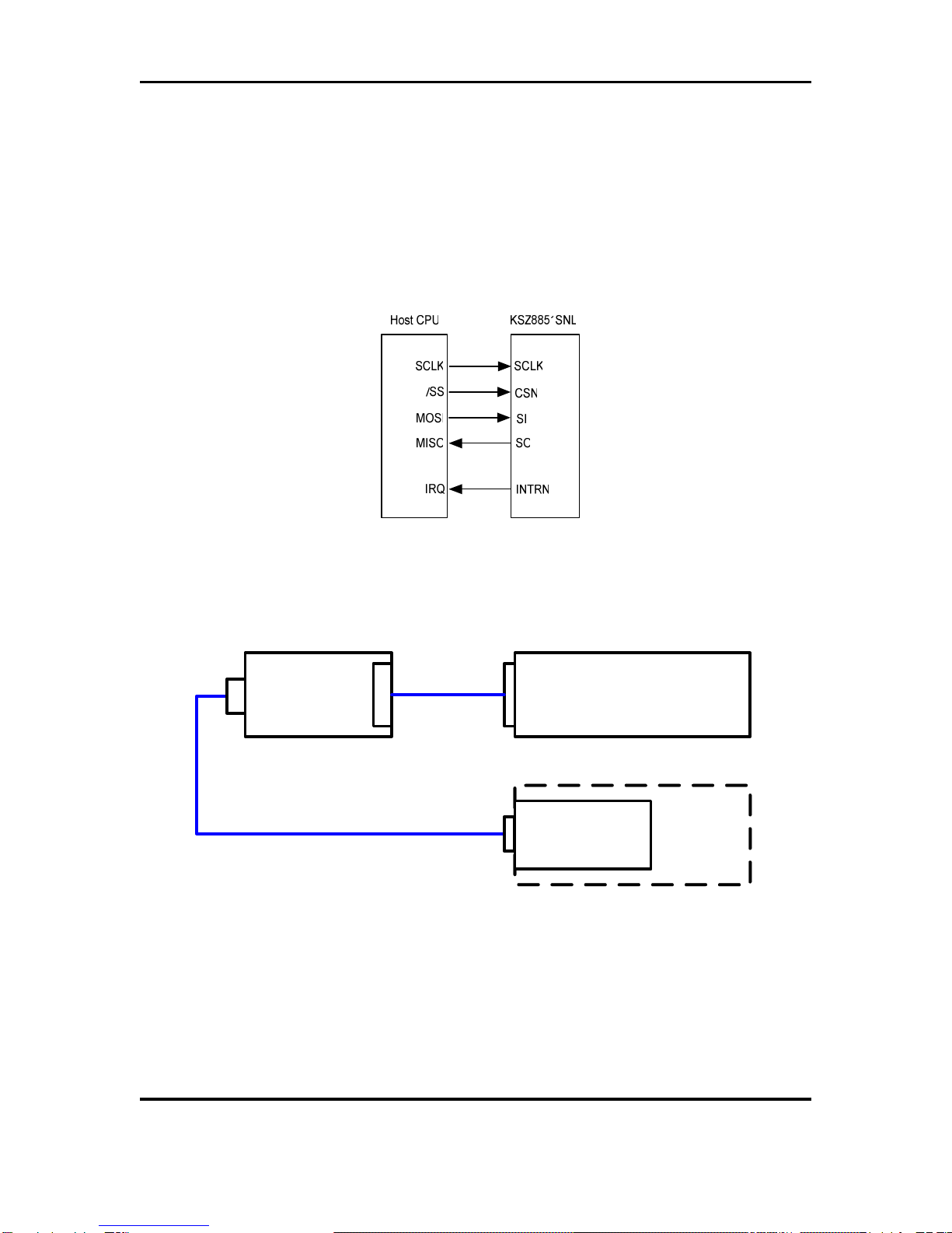
The KSZ8851SNL comes with a 32-pin, lead-free QFN (5mm x 5mm) package and provides an
ideal solution for applications requiring Serial Peripheral Interface (SPI) between single-port
Ethernet Controller and Host microcontroller.
This evaluation board is designed as a stand alone without microcontroller on board. By default
the KSZ8851SNL-Eval board comes with an operation of no EEPROM for KSZ8851SNL device.
Customer can directly wire the board for SPI interface. The purpose is to provide a simple tool
that can be used to evaluate the KSZ8851SNL device by connecting via headers to customer
provided Microcontroller or Non-PCI hardware platform.
Micrel provides a basic software driver based on SPI Interface solution and different operating
system platforms to evaluate the KSZ8851SNL functionality and performance. The software
includes a configuration utility to allow quick and easy device setup, initialization and
transmit/receive packet. All KSZ8851SNL configuration pins, control signals and SPI interface are
accessible either by jumpers, test points or headers.
2.0 Board Features
•One KSZ8851SNL 32-pin Single-Port Ethernet Controller with SPI for host interface
•Single +5V/GND power input from headers
•RJ-45 Jack for Fast Ethernet cable interface
•HP Auto-MDIX for automatic detection and correction for straight-through and crossover
cables
•Two on board LDO voltage regulators, one for VDD_IO and the other for 3.3VA
•One AT93C46 for external EEPROM interface
•Two LED indicators for port status and activity
•One LED indicator for 3.3V output ready
•One LED indicator for Power Management Event (PME) output status
•Jumpers to configure strapping pin and VDD_IO voltage option
•Headers to wire the SPI interface from external hardware platform
•Manual reset button for quick reboot device after re-configuration of strapping pin
3.0 Evaluation Kit Contents
The KSZ8851SNL Evaluation Kit includes the following hardware:
•KSZ8851SNL Evaluation Board
The KSZ8851SNL Data Sheet and Hardware Design Package with the following collaterals that
can be downloaded from Micrel’s website at http://www.micrel.com
•KSZ8851SNL Eval Board Schematic (PDF and OrCAD DSN file)
•KSZ8851SNL Eval Board Gerber File (PDF version included)
•KSZ8851SNL Eval Board User’s Guide (this document and included BOM)
•KSZ8851SNL IBIS Model

KSZ8851SNL-Eval Evaluation Board User’s Guide Rev. 1.1
Micrel, Inc. April 21, 2010
6/11
4.0 Hardware Description
The KSZ8851SNL-Eval (shown in Figure 1) comes in a compact form factor and plugs directly
into industry standard test equipment such as Spirent SmartBits, the other side of board is wired
to external host SPI interface through headers. Configuration of the KSZ8851SNL is
accomplished through on-board jumper selections and/or by register access via the host SPI
Interface.
Figure 1. KSZ8851SNL Evaluation Board
Other features include a RJ-45 Jack for Fast Ethernet cable connection, transformer (Pulse
H1102) to block DC level and provide a true AC coupling, EEPROM (Atmel AT93C46) to load
MAC address when it is enabled, jumper to select LDO output for VDD_IO voltage,
programmable LED indicators for reporting port link status and activity, and a manual reset button
for quick reboot after re-configuration of strapping pins.
The KSZ8851SNL-Eval receives +5V DC input power supply from its Headers JP1.

KSZ8851SNL-Eval Evaluation Board User’s Guide Rev. 1.1
Micrel, Inc. April 21, 2010
7/11
4.1 Host SPI Interface
The KSZ8851SNL supports a SPI interface in slave mode. In this mode, a external SPI master
device (micro-controller or CPU) supplies the operating serial clock (SCLK), chip select (CSN)
and serial input data (SI) which is clocked in on the rising edge of SCLK to KSZ8851SNL device.
Serial output data (SO) is driven out by the KSZ8851SNL on the rising edge of SCLK to external
SPI master device. The falling edge of CSN is starting the SPI operation and the rising edge of
CSN is ending the SPI operation. The SCLK stays low state when SPI operation is idle. Figure 6
shows the SPI interface connection for KSZ8851SNL.
Figure 2. SPI Interface to KSZ8851SNL
The KSZ8851SNL-Eval board receives +5V power from the header JP1 (pin 1). Figure 3 shows
the Host SPI interface connection with Spirent SmartBits for system set-up and performance test.
Any Microcontroller
Hardware Platform with
SPI Interface
SmartBits
SX-7410
Module
Spirent
SmartBits
2000
Chassis
KSZ88851SNL
-EVAL
RJ-45
SPI I/F
JP1
J1
Figure 3. KSZ8851SNL-Eval Host SPI Interface Connection with Spirent SmartBits
The KSZ8851SNL-Eval has a 10-pin header (JP1) for Host SPI interface to any external
Microcontroller hardware platform. Table 1 lists 4-wire SPI pin outs for the Host interface on
header JP1. Table 2 lists the rest of control signals and power/ground pin outs for the Host
interface on header JP1.

KSZ8851SNL-Eval Evaluation Board User’s Guide Rev. 1.1
Micrel, Inc. April 21, 2010
8/11
Pin #
(JP1) SPI Interface
Signal Name Description
4 SCLK Serial clock input from host CPU for SPI interface. This
clock speed can run up to 50 MHz
6 SI Serial data in from host CPU for SPI interface
8 CSN Chip Select Enable (Active low) from host CPU for SPI
interface
10 SO Serial data out to host CPU for SPI interface
Table 1. Header JP1 – Host Connection for SPI Interface
Pin # (JP1) Power & Control
Signal Names Description
1 5.0V_IN +5V power supply inputs for this board
2, 9 GND Ground inputs/pins
3 RSTN Reset input from host CPU
5 PME Power Management Event output to host CPU
7 INTRN Interrupt output to host CPU
Table 2. Header JP1 – Host Connection for Control and Power
4.2 Jumper Setting & Definition
The KSZ8851SNL-Eval does not require any jumper for normal operation except the VDD_IO
option. During power-up, the KSZ8851SNL is configured using the chip’s internal pull-up and pull-
down resistors with its default strapping pin value which will set this device in operation of without
EEPROM. Jumpers are provided to override the default settings, allowing for quick configuration
and re-configuration of the board. To override the default settings, simply select and close the
desired jumper setting(s) and toggle the on-board manual reset button (S1) for the new setting(s)
to take effect.
The KSZ8851SNL-Eval jumper settings are defined in Table 3 below.
Jumper Definition Setting Description
JP2 EED_IO OFF (Default) OFF: EEPROM is not present
ON: EEPROM is present
JP3 1.8V OFF (Default) OFF: VDD_IO is 2.5V or 3.3V
ON: VDD_IO is 1.8V
JP4 3.3V ON (Default) ON: to select 3.3V (JP5 and JP6 must be OFF)
OFF: De-select 3.3V
JP5 2.5V OFF (Default) ON: to select 2.5V (JP4 and JP6 must be OFF)
OFF: De-select 2.5V
JP6 1.8V OFF (Default) ON: to select 1.8V (JP4 and JP5 must be OFF)
OFF: De-select 1.8V
Table 3. KSZ8851SNL-Eval Jumper Definition

KSZ8851SNL-Eval Evaluation Board User’s Guide Rev. 1.1
Micrel, Inc. April 21, 2010
9/11
4.3 Power Supply and Test Point Definition
The KSZ8851SNL-Eval is supplied from external +5.0V DC power through a Header (pin 1 at
JP1), this +5.0V DC input is converted to both +3.3V with a Micrel LDO voltage regulator (U3,
MIC5209BM) for 3.3VA analog power and VDD (option for 3.3V, 2.5V or 1.8V) with a Micrel LDO
voltage regulator (U4, MIC5209BM) for VDD_IO digital power. The KSZ8851SNL contains an
internal +1.8V LDO, to provide its core, analog and PLL voltages.
The KSZ8851SNL-Eval has four test points. They are defined in the following Table 4.
Test Point Definition
TP1 1.8V digital core voltage output measurement from
KSZ8851SNL internal LDO
TP2 3.3V Power supply measurement for VDD_IO
TP3 3.3VA Power supply measurement for VDD_A3.3
TP4 5.0V External power supply 5.0V_IN measurement
Table 4. KSZ8851SNL-Eval Test Point Definition
4.4 RJ-45 Connector and Transformer
The RJ-45 Jack (J1) connects to standard CAT-5 Ethernet cable to interface with 10Base-
T/100Base-TX Ethernet devices. The LAN interface on the KSZ8851SNL is connected to a
transformer (T1) with 50 ohm termination resistors for both TX+/- and RX+/- differential pairs. The
line side of the transformer is connected to the RJ-45 connectors (J1).
J1 also supports Auto-MDIX and Auto-Negotiation / Forced Modes.
4.5 EEPROM and LED Indicators
It is optional in the KSZ8851SNL to use an external EEPROM. The EED_IO (JP2) must be pulled
high (Jumper: ON) to use external EEPROM.
An external serial EEPROM with a standard microwire bus interface is used for non-volatile
storage of information such as the host MAC address. The KSZ8851SNL can detect if the
EEPROM is either a 1KB (93C46) or 4KB (93C66) EEPROM device. The EEPROM must be
organized as 16-bit mode.
The KSZ8851SNL EEPROM format is given in Table 5.
WORD 15 8 7 0
0H Reserved
1H Host MAC Address Byte 2 Host MAC Address Byte 1
2H Host MAC Address Byte 4 Host MAC Address Byte 3
3H Host MAC Address Byte 6 Host MAC Address Byte 5
4H – 6H Reserved
7H-3FH Not used for KSZ8851SNL (available for user to use)
Table 5. KSZ8851SNL EEPROM Format

KSZ8851SNL-Eval Evaluation Board User’s Guide Rev. 1.1
Micrel, Inc. April 21, 2010
10/11
A dual LED indicator (LED1) is located adjacent to the RJ-45 Connector (J1). The top LED is
connected to LED1 (pin 32) and bottom LED is connected to LED0 (pin 1) of the KSZ8851SNL.
The two LEDs are programmable to LED mode ‘0’ or ‘1’ via register 0xC6 bits [9], and are defined
in the following Table 6.
LED Mode
0 (Default) 1
LED1 (Top) 100BT ACT
LED1 (Bottom) LINK/ACT LINK
Table 6. KSZ8851SNL-Eval Port Status LED Definition
Table 7 shows the rest of LEDs definition.
LED Color Description
LED2 Green Power Management Event (PME) Status
LED3 Red 3.3V Power available indicator
Table 7. KSZ8851SNL-Eval LED Definition
4.6 Board Reset
The KSZ8851SNL-Eval generates a reset signal from the reset circuitry during power up. It also
provides a push button S1 reset circuit to reset the KSZ8851SNL device. During power up, the
board is automatically reset. User can also press reset button S1 on the board for a manual reset.

KSZ8851SNL-Eval Evaluation Board User’s Guide Rev. 1.1
Micrel, Inc. April 21, 2010
11/11
5.0 Bill of Materials
KSZ8851SNL Eval Board (Revision 1.1)
Table of contents
Other Micrel Motherboard manuals

Micrel
Micrel ULDO MIC5301/18 User manual

Micrel
Micrel KSZ8873MML User manual

Micrel
Micrel SY87725L User manual

Micrel
Micrel MIC2039 User manual

Micrel
Micrel MIC7401 User manual

Micrel
Micrel MIC23099 User manual

Micrel
Micrel MIC33050 User manual

Micrel
Micrel MIC23030 User manual

Micrel
Micrel SY88212L User manual

Micrel
Micrel SY88216L User manual

Micrel
Micrel KS8721BL/SL User manual

Micrel
Micrel KSZ8895 User manual

Micrel
Micrel KSZ9021RL-EVAL User manual

Micrel
Micrel MIC2786 User manual

Micrel
Micrel MIC45208 User manual

Micrel
Micrel KSZ9031MNX User manual

Micrel
Micrel KSZ8841-PMQL User manual

Micrel
Micrel mic28510 User manual

Micrel
Micrel KSZ8873MLL User manual

Micrel
Micrel KSZ8862-16 MQL User manual