Micrel SY88147DL Operating and maintenance instructions
3.3V, 1.25Gbps PECL Limiting Post
Amplifier with High-Gain TTL Loss-of-
Signal
SY88147DL Evaluation Board
Micrel Inc. • 2180 Fortune Drive • San Jose, CA 95131 • USA • tel +1 (408) 944-0800 • fax + 1 (408) 474-1000 • http://www.micrel.com
January 2006
M9999-011606-A
General Description
The SY88147DL high-sensitivity, limiting post
amplifier is designed for use in fiber-optic receivers.
The device connects to typical transimpedance
amplifiers (TIAs). The linear signal output from TIAs
can contain significant amounts of noise and may vary
in amplitude over time. The SY88147DL quantizes
these signals and outputs PECL-level waveforms.
The SY88147DL operates from a single +3.3V power
supply, over an industrial temperature range of –40°C
to +85°C. With its wide bandwidth and high gain,
signal with data rates up to 1.25Gbps, and as small as
5mV
pp
can be amplified to drive devices with PECL
inputs.
The SY88147DL features an open-collector, TTL loss-
of-signal (LOS) indicator. The LOS function has a high
gain input stage for increased sensitivity. A
programmable loss-of-signal level set pin (LOS
LVL
)
sets the sensitivity of the input amplitude detection.
LOS asserts high if the input amplitude falls below the
threshold set by LOS
LVL
and de-asserts low otherwise.
The enable bar input (/EN) de-asserts the true output
signal without removing the input signal. The LOS
output can be fed back to the enable bar (/EN) input to
maintain output stability under a loss-of-signal
condition. Typically, 3.5dB LOS hysteresis is provided
to prevent chattering.
This manual provides information on the SY88147DL
evaluation board. It should be used in conjunction with
the SY88147DL data sheet, which contains the full
specifications of the SY88147DL.
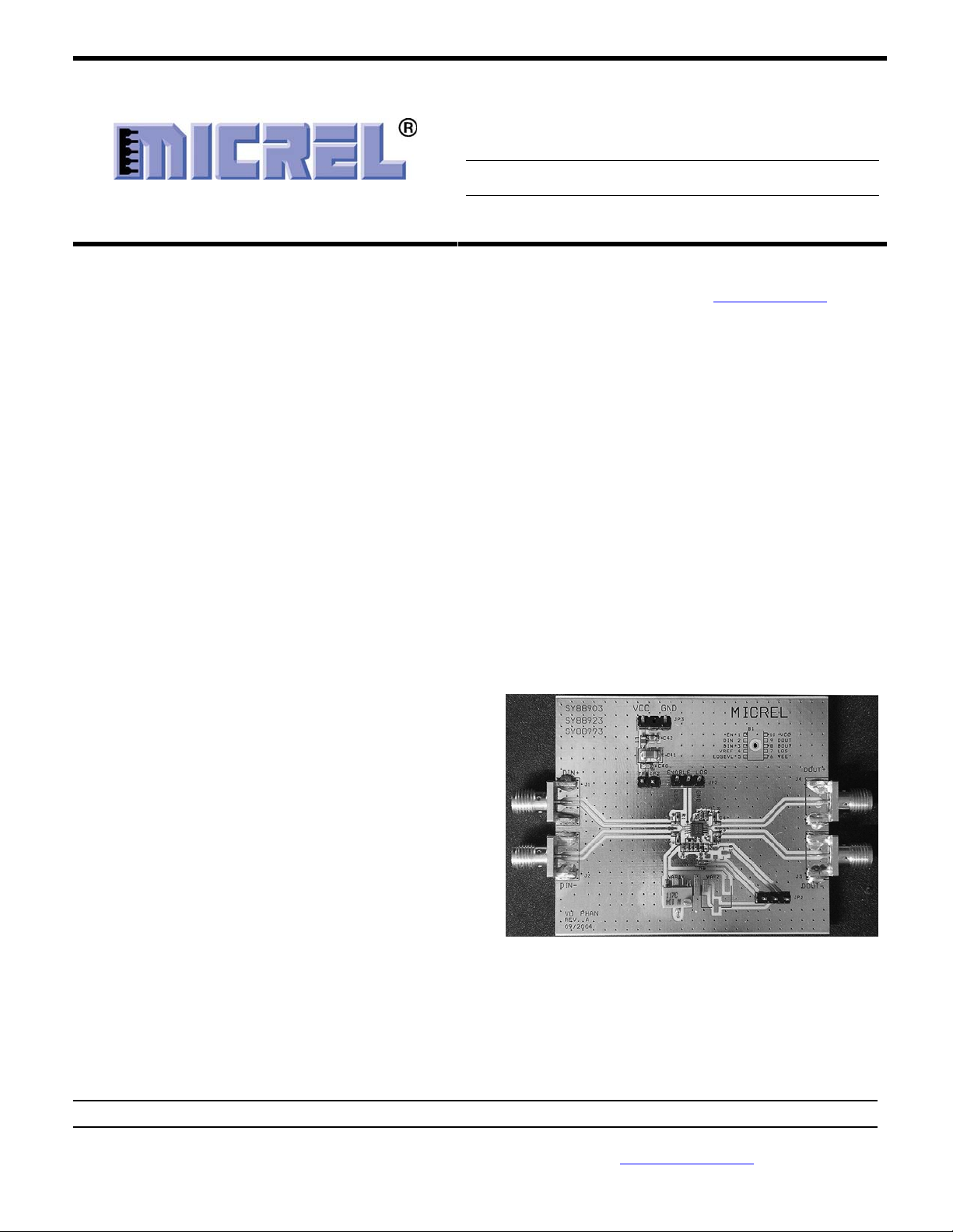
The SY88147DL evaluation board enables fast and
thorough evaluation of the SY88147DL. The board is
an easy-to-use, single supply design. It’s designed to
be driven by a high-speed, pattern generator and
provides onboard 50terminations for the generator’s
outputs. The input termination network also provides
the required input bias of V
CC
–1.3V for the
SY88147DL.
The SY889147DL evaluation board is intended to
terminate to a 50scope and provides for simple user
adjustability of the LOS threshold through the
adjustment of an on-board potentiometer.
All data sheets and support documentation can be
found on Micrel’s web site at: www.micrel.com.
Features
•Single 3.3V supply
•DC-to-1.25Gbps operation
•Low-noise PECL data outputs
•LOS Indicator
•Chatter-free open-collector TTL loss-of-signal
(LOS) output with internal 4.75kpull-up resistor
•TTL /EN input
•Programmable LOS level set (LOS
LVL
)
•AC-coupled I/O with SMA connectors
•50input network termination
Related Documentation
•SY88147DL, 3.3V, 1.25Gbps PECL Limiting Post
Amplifier w/ High-Gain TTL LOS Data Sheet
Evaluation Board

Micrel, Inc. SY88147DL Evaluation Board
January 2006
2 M9999-011606-
A
Measurement Setup
Equipment used for measurements:
1. Agilent 83752A Synthesized Sweeper
2. Agilent 70004A Display
3. Agilent 70843B Error Performance Analyzer
4. Agilent 86100A Wide-Bandwidth
Oscilloscope
5. Two (2) MCL BW S15W2 40dB Attenuators
6. Agilent E3620A DC Power Supply
7. Tektronix DMM157 Multimeter
8. Matched High-Speed Cables w/SMA
Connectors
Note:
Items 1 through 3 constitute the BERT stack
Figure 1. Setup for Measurement

Micrel, Inc. SY88147DL Evaluation Board
January 2006
3 M9999-011606-
A
Setup for Measurements
This sub-section explains how to connect and setup the
SY88147DL evaluation board, per Figure 1. Always
ensure that proper ESD precautionary measures are
taken before handling sensitive electronic equipment,
including the SY88147DL evaluation board.
1. Set E3620A output to 3.3V and then turn off
E3620A. Connect E3620A’s positive lead to
V
CC
post, negative lead to GND post.
2. Configure Agilent BERT stack:
a. Set the 83752A Synthesized Sweeper to
1.25GHz.
b. From the 70004A’s Pattern menu, choose
the PRBS 2
23
–1 pattern.
c. From the 70004A’s Trigger menu:
i. Choose clock as trigger output
ii. Choose CLK/8 for divider
d. From the 70004A’s Data menu:
i. External Termination = DC termination
0V
ii. Attenuation = 40dB
iii. Amplitude = 5mV
PP
iv. Hi-Level = 0V
v. Tracking = ON
vi. Polarity = NORMAL
vii. Data Output = ON
viii. Crossing = 0
3. Connect 70843V’s trigger output to
86100A’s trigger input.
4. Use J1 to short /EN to GND on SY88147DL
evaluation board.
5. Connect DIN and /DIN on SY88147DL
evaluation board to 70843V’s data outputs
through 40dB attenuators
a. Connect 40dB attenuators directly to the
board rather than the 70843V’s data outputs
to allow a larger and cleaner signal to pass
through the connecting SMA cables.
6. Connect DOUT and /DOUT on SY88147DL
evaluation board to 86100A’s inputs.
7. Set DMM157 to display voltage. Connect
positive lead to LOS header on J1 and
connect negative lead to GND.
8. Turn on E3620A. Typical power supply
current should be ~45mA, including the
SY88147DL’s current and current through the
on-board 130output pull-down resistors at
3.3V supply voltage. Excessive current
usually means the power supply leads have
been connected backwards. Be careful of this.
9. To configure 86100A oscilloscope:
a. Verify a trigger signal is present by
checking that the Trigger Source button is
lit.
i. Depress this button to choose
external source if necessary.
ii. Adjust trigger level if necessary.
b. Press Eye/Mask Mode on front panel.
c. Choose NRZ Eye Measurements from
on-screen display.
d. Choose RMS Jitter, Rise Time, Fall Time
and Eye Amplitude measurements from
on-screen selection list.
Micrel, Inc. SY88147DL Evaluation Board
January 2006
4 M9999-011606-
A
Measurements
The SY88147DL evaluation board assumes the use of
a 50Ωscope to terminate the SY88147DL. The
following sub-sections detail various metrics that the
SY88147DL evaluation board can measure:
1. Eye pattern generation including jitter and
rise/fall times:
a. Set 70004’s Data amplitude to 5mV
PP
.
b. Press Autoscale on oscilloscope. The eye
pattern should automatically display on the
scope. If not, verify the steps listed in the
“Setup for Measurements” section are
completed. Sometimess the waveform
needs to be manually adjusted to fit the
display. Use the Time Scale and Voltage
Scale knobs on the front panel of the scope
to adjust this.
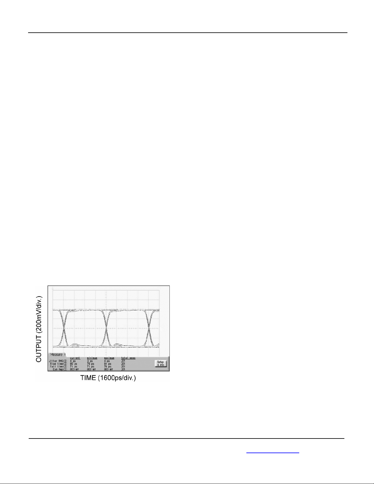
c. Observe measurements on scope’s
display. The rise and fall times should be
less than 260ps, amplitude around 800mV
(1600mV
pp
) and jitter around 10ps
RMS
.
i. Note that the output amplitude varies
with the input amplitude until the
SY88147DL enters limiting mode at
around 12.5mV
pp
input. The
SY88147DL has a typical gain of
42dB. Hence, 5mV
pp
input will give
only 630mV
pp
output, whereas
20mV
pp
input will give 1600mV
pp
output.
Figure 2. Typical SY88147DL Eye Pattern
2. Mask testing:
a. Press Eye/Mask Mode on front panel of
scope.
b. Choose Mask Testing from on-screen
display.
c. Choose Open Mask from on-screen
selection list.
i. Select and open the appropriate Mask
d. Choose Start Mask Testing from on-
screen selection list. Waveform should
automatically display with appropriate
mask regions and testing will start. If not,
verify the steps listed in the “Setup for
Measurements” section are completed.
3. BER testing:
a. Feedback the SY88147DL evaluation
board’s DOUT output to the 70843V’s
BERT Data input.
b. Feedback the 70843V’s Clock output to
the 70843V’s BERT Clock input.
c. Set 70004’s Data amplitude to 5mV
PP
.
d. From the 70004A’s Gating menu:
i. Choose a gate condition. The options
are: gate by time, errors or bits.
Choose bits, but this is of no
relevance because there should be
no errors, and the test will run forever
until manually interrupted if gate by
errors is chosen.
ii. Choose single gating period
iii. Choose run gating
iv. 70004A will reset error count and
synchronize SY88147DL’s
transmitted bit stream to 70843V’s
generated bit stream. If
synchronization does not occur, it is
sometimes due to cable length. Try
using different length cables (each
pair is of equal length, of course) is to
achieve synchronization. If this is
unavailable, another trick is to adjust
the 83752A’s frequency to a slightly
higher or lower value.
v. At the end of gating period, there
should be no errors.

Micrel, Inc. SY88147DL Evaluation Board
January 2006
5 M9999-011606-
A
4. LOS hysteresis:
a. The SY88147DL evaluation board
provides a potentiometer to allow for easy
adjustment of LOS
LVL
without the need for
an extra power supply. LOS
LVL
taps off
the potentiometer whose ends are
connected from V
CC
to V
REF
. V
REF
is a
reference voltage of approximately V
CC
–
1.3V. Hence, LOS
LVL
can be set to any
voltage from V
CC
to V
CC
–1.2V, as
specified in the SY88147DL data sheet.
The potentiometer creates a voltage
divider. Thus,
()
()
⎥
⎦
⎤
⎢
⎣
⎡
+
×
−= 2.8kkR
kR1.3V
(V)VLOS
CCLVL
Where R is the resistance of the
potentiometer VAR1. The proceeding steps
show how to find the LOS hysteresis for a
5mV
pp
LOS- assert voltage without
measuring R
:
b. Set 70004’s Data amplitude to 5mV
PP
.
c. Verify DMM157 displays that LOS is
HIGH.
d. If not, turn potentiometer VAR1 until LOS
is HIGH.
e. Slowly increase 70004A’s Data amplitude
until LOS becomes LOW. Note the
voltage at which LOS becomes LOW.
This is the LOS de-assert voltage.
f. Now slowly lower the 70004A’s Data
amplitude until LOS becomes HIGH
again. This should be the starting voltage
of 5mV
PP
. This is the LOS assert voltage.
g. Hysteresis (dB) = 20log (LOS De-assert
voltage/LOS Assert voltage). This should
be >2dB.
Evaluation Board Layout
The SY88147DL evaluation board enables fast and
thorough evaluation of the SY88147DL 1.25Gbps
PECL High-Sensitivity Limiting Post Amplifier with TTL
High-Gain Loss-of-Signal. The board is an easy-to-
use, 4-layer, high-speed coplanar design that uses
Rogers 4003 dielectric material to achieve high
bandwidth. The layer stack is shown in Table 1.
Layer Definition
L1 Signal/GND
L2 GND
L3 VCC
L4 GND
Table 1. Layer Stack
Micrel, Inc. SY88147DL Evaluation Board
January 2006 6
M9999-011606-
A
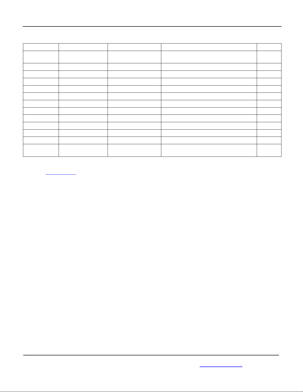
Bill of Materials
Item Part Number Manufacturer Description Qty.
C1, C2, C3,C4,
C21, C23, C25
VJ0402Y104KXXAT Vishay
(1)
0.1µF Surface Mount Capacitor, Size 0402 7
C20, C22, C24 VJ0402Y222KXXAT Vishay
(1)
220pF Surface Mount Capacitor, Size 0402 3
C41 293D106X0025CT Vishay
(1)
10µF Surface Mount Capacitor, Size C 1
C42 293D105X0025CT Vishay
(1)
1µF Surface Mount Capacitor, Size C 1
L1 BLM21A102F Murata
(2)
Ferrite Bead, Size 0603 1
J1, VCC TSW-103-07-S-S Samtec
(3)
0.1mil Center through hole terminal strip
R1, R2 CRCW040249R9F Vishay
(1)
49.9Surface Mount Resistor, Size 0402 2
VAR1 3269W-1-153G Bourns
(4)
15kTrimmer 1
R3, R4 CRCW04021300F Vishay
(1)
130Surface Mount Resistor, Size 0402 2
R5 CRCW04023001F Vishay
(1)
3kSurface Mount Resistor, Size 0402 1
R7 CRCW04025001F Vishay
(1)
5kSurface Mount Resistor, Size 0402 1
J1-J4 142-0701-851 Johnson Components
(1)
End Launch SMA 4
U1 SY88147DL Micrel
(5)
3.3V 1.25Gbps PECL Low-Power Limiting
Post Amplifier w/ High-Gain TTL LOS 1
Notes:
1. Vishay: www.vishay.com.
2. Murata: www.murata.com.
3. Samtec: www.samtec.com.
4. Bourns: www.bourns.com.
5. Johnson Components: www.johnsoncomponents.com.
6. Micrel, Inc.: www.micrel.com.

Micrel, Inc. SY88147DL Evaluation Board
January 2006 7
M9999-011606-
A
HBW Support
Hotline: 408-955-1690
Application Hints and Notes
For application notes on high-speed termination on
PECL and LVPECL products, clock synthesizer
products, SONET jitter measurement, and other High
Bandwidth products, go to Micrel’s website at:
http://www.micrel.com/. Once in Micrel’s website,
follow the steps below:
1. Click on “Product Info”.
2. In the Applications Information Box, choose
“Application Hints and Application Notes.”
MICREL, INC. 2180 FORTUNE DRIVE SAN JOSE, CA 95131 USA
TEL +1 (408) 944-0800 FAX +1 (408) 474-1000 WEB http://www.micrel.com
The information furnished by Micrel in this data sheet is believed to be accurate and reliable. However, no responsibility is assumed by Micrel for its
use. Micrel reserves the right to change circuitry and specifications at any time without notification to the customer.
Micrel Products are not designed or authorized for use as components in life support appliances, devices or systems where malfunction of a
product can reasonably be expected to result in personal injury. Life support devices or systems are devices or systems that (a) are intended for
surgical implant into the body or (b) support or sustain life, and whose failure to perform can be reasonably expected to result in a significant injury
to the user. A Purchaser’s use or sale of Micrel Products for use in life support appliances, devices or systems is a Purchaser’s own risk and
Purchaser agrees to fully indemnify Micrel for any damages resulting from such use or sale.
© 2006 Micrel, Incorporated.
Table of contents
Other Micrel Motherboard manuals

Micrel
Micrel SY87725L User manual

Micrel
Micrel MIC2786 User manual

Micrel
Micrel MIC7401 User manual

Micrel
Micrel KSZ8873MML User manual

Micrel
Micrel KSZ9031MNX User manual

Micrel
Micrel KSZ8873MLL User manual

Micrel
Micrel KSZ9021RL-EVAL User manual

Micrel
Micrel KSZ8463ML User manual

Micrel
Micrel KS8995MA User manual

Micrel
Micrel KS8721BL/SL User manual

Micrel
Micrel mic28510 User manual

Micrel
Micrel MIC23031-4YMT EV User manual

Micrel
Micrel MIC2039 User manual

Micrel
Micrel MIC2169A User manual

Micrel
Micrel SY88216L User manual

Micrel
Micrel KSZ8841-PMQL User manual

Micrel
Micrel SY88212L User manual

Micrel
Micrel KSZ8081MNX User manual

Micrel
Micrel MIC45208 User manual

Micrel
Micrel KSZ8895 User manual


