MICRO-AIR MAE2200 User manual

AIR CLEANERS
MAE2200
OWNER’S MANUAL
CAUTION
READ COMPLETE INSTRUCTIONS BEFORE OPERATING.
PLEASE FILE FOR FUTURE REFERENCE.
®
2
MAE2200
®
MODEL MAE2200 SPECIFICATIONS
Input Volts: 208-230/460 VAC 60Hz, 3-phase
Max. Current:208-230 VAC - 7.2 amps
460 VAC - 3.6 amps
Motor: 2 HP 3-phase TEFC Motor
Dimensions: 22"H. x 26"W. x 78"L. (cabinet and plenum)
Shipping WT:375 lbs. without arms
Actual WT: 325 lbs. without arms
ARM SPECIFICATIONS
Arm Length (Horizontal Reach): 14' - 8" dia.
10' - 8" dia.
8' - 8" dia.
Actuator:1/8 HP totally enclosed motor, 12" stroke at 35 in/min.
Input Volts: 120 VAC 60 Hz
Current: 2.1 amps
Control Circuit: 24 VAC
Hood Lamp: 12 VAC halogen at 4 amps
Weights: 8" dia. - 14' = 48 lbs
8" dia. - 10' = 40 lbs
8" dia. - 8' = 35 lbs
PACKAGE CONTENT
1 ea. MAE2200 with Plenum
1 ea. *Arm Assembly
1 ea. Owners Manual
1 ea. Arm Installation Kit
*Dual Arm units will contain two each of this item.
UNCARTONING INSTRUCTIONS
1. The MAE2200 is packaged in two cartons. Carton one
has the MAE2200 with plenum and base collars banded
to the wooden skid. Carton two contains the arm
assembly(s).
2. Cut the metal banding that secures the unit to the skid and
remove all cartoning, plastic wrap and padding.
3. Remove blower access panel. Inspect blower, motor, belt
tension and power leads for damage. Replace blower
access panel after inspection is complete. Report any
shipping damage to freight line carrier.
4. Open large door on the side of cabinet. Lift handles
outward and rotate to open door. Remove the plastic bag
from the filter and cut the paper band that is holding the
filter pockets in place. Reinstall the bag filter.
5. Open carton two and remove arm. Remove packaging
supports from arm assembly. Be careful not to damage the
steel tubes on the arm during unpackaging.
6. Inspect the arm for damage that may have been caused
during shipping. Immediately report any such damage to
the shipping carrier.
7. Examine the arm and compare it to the parts list
description to verify that all components have been
received. If a component is missing from the assembly,
contact your Micro Air Representative.
INSTALLATION INSTRUCTIONS
CAUTION: THIS UNIT WITHOUT THE ARMS WEIGHS
APPROXIMATELY 325 POUNDS. THEREFORE,
APPROPRIATE MANPOWER OR EQUIPMENT IS
RECOMMENDED FOR SAFE INSTALLATION.
CAUTION: DO NOT ATTEMPT TO MOUNT UNIT USING
THE FOUR THREADED HOLES ON THE BOTTOM SIDE
OF CABINET.
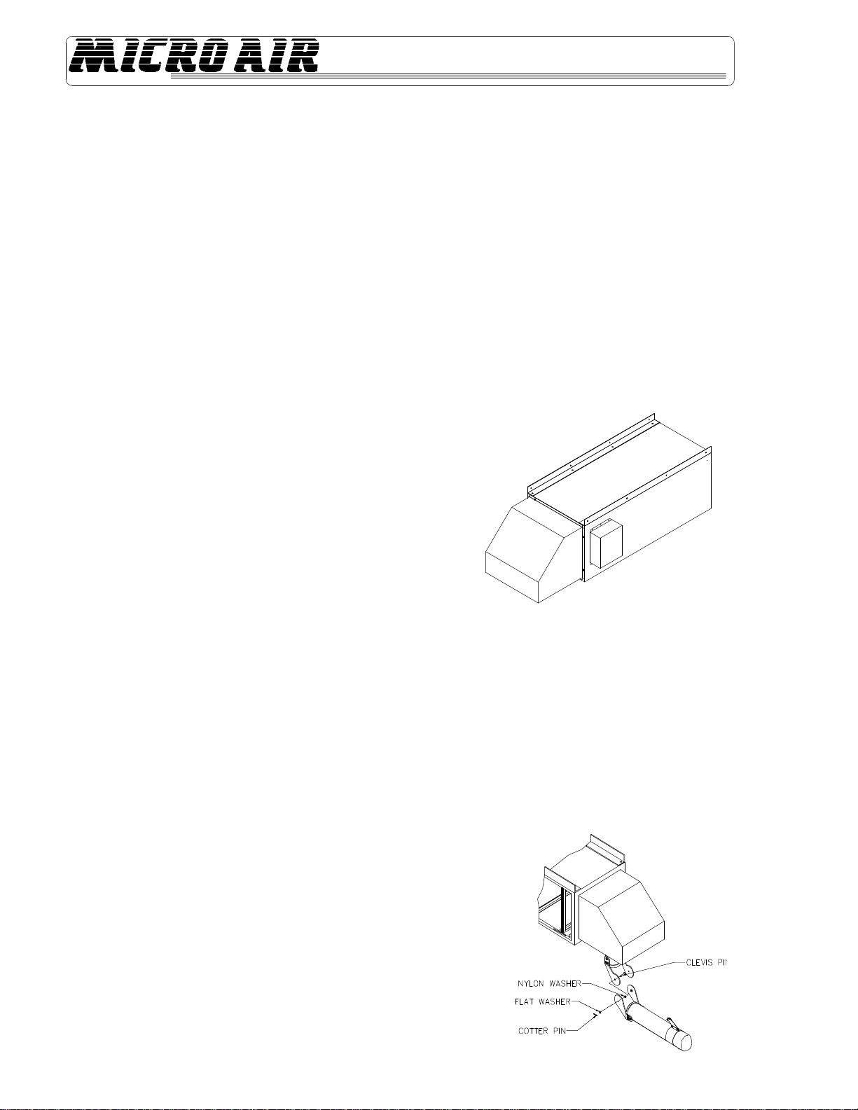
1. Install unit from solid structural support. Unit may then be
suspended with a rigid hanger assembly having sufficient
strength to support cabinet and the additional uneven load
of arm assembly(s) fully extended. (See FIG. 1.)
WARNING: DO NOT ATTEMPT TO INSTALL BY
SUSPENDING WITH CHAINS. ALL THREAD, ANGLE IRON,
OR OTHER FIXED SUPPORTS ARE REQUIRED.
ARM INSTALLATION INSTRUCTIONS
NOTE: Due to the numerous system combinations available,
some of the following installation steps may not be applicable.
Follow steps that directly address the specific system being
installed.
1. Assemble the arm(s) to the base collar using the hardware
preassembled to the arm as shown in FIG. 2.
FIG. 1
FIG. 2
3
MAE2200 ®
NOTE: During the step, it is recommended that two people be
used: one to support the arm assembly, while the other
attaches hardware to clamp arm assembly onto base collar.
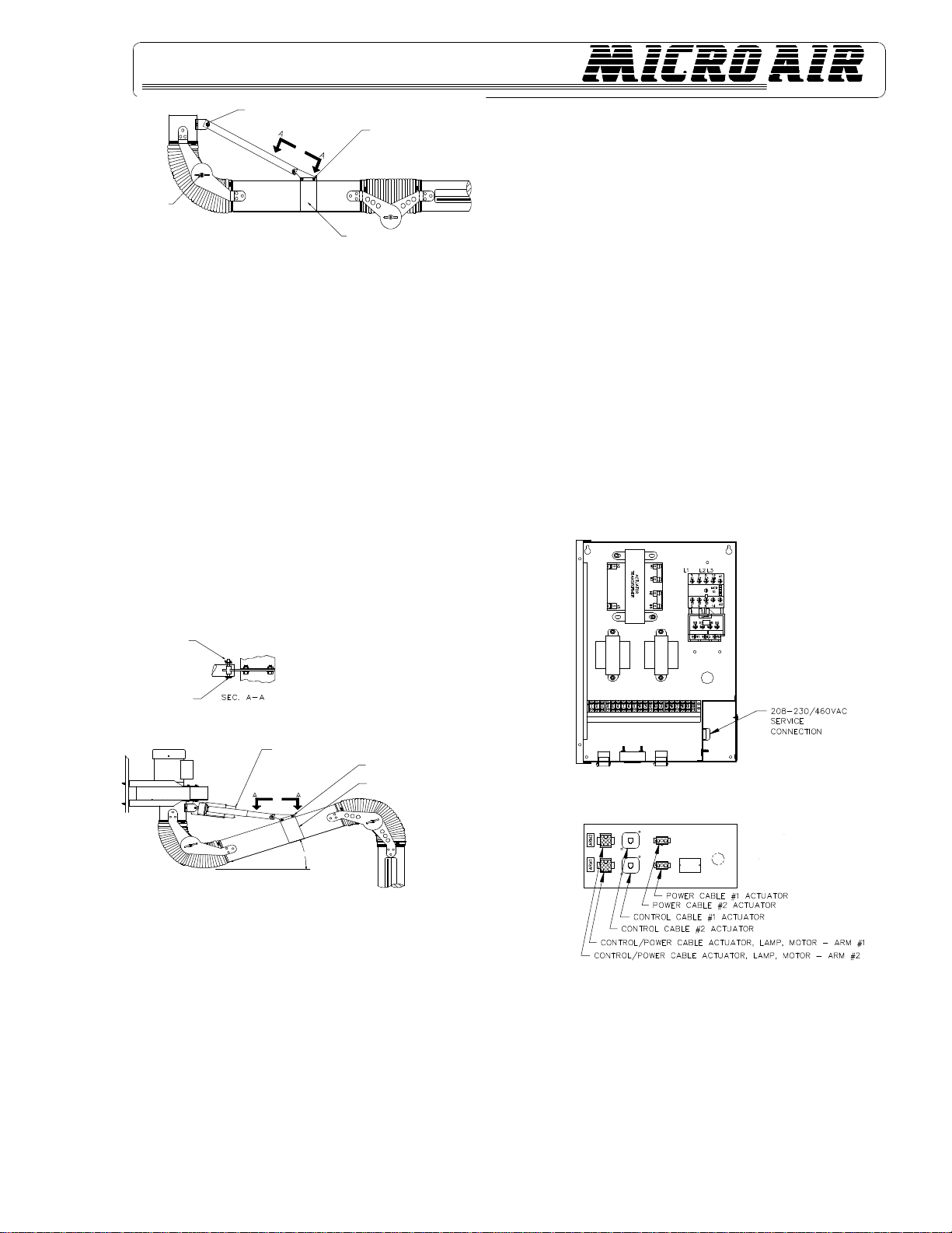
2. Once the arm assembly is attached to the base collar,
raise the arm to a horizontal position (arm parallel to floor).
Using the hardware provided, attach the rigid pipe section
as shown in FIG. 3.
3. If vertical adjustment of the arm is required, adjustment
can be made by repositioning the clamp band along the
pipesection.
4. To reposition the clamp band, loosen the 1/4" bolts on
clamp band so that the clamp band can be moved for arm
adjustment.
NOTE: This is for fixed arm models only. If your arm has a
linear actuator proceed to Step 5.
5. For models that use a motorized base joint, assemble the
linear actuator to the base collar with hardware provided.
Then assemble other end to the clamp band, similar to
that of the fixed joint assembly. (See FIG. 4.)
WARNING: FOR MODELS WITH A LINEAR ACTUATOR
DO NOT RELOCATE CLAMP BAND IN SUCH A WAY THAT
LINEAR ACTUATOR COULD COME IN CONTACT WITH
MAE2200 PLENUM OR OTHER OBJECT WHEN
ACTUATOR IS FULLY RETRACTED.
ELECTRICAL INSTALLATION
CAUTION: INSTALLATION CAN CAUSE EXPOSURE TO
LIVE COMPONENTS. DISCONNECT ELECTRICAL POWER
BEFORE PROCEEDING WITH INSTALLATION.
1. LINEAR ACTUATOR INSTALLATION:
The linear actuator is supplied with a 3-conductor input
power cable and a phone-type control cable.
A. The input power cable is supplied with a 3-pin
quick-connect plug which plugs into the 3-pin
receptacle located below the electrical box.
B. The phone-type control cable is supplied with
two plugs that plug into the actuator on one end
and a phone jack receptacle located below the
electrical box.
2. LOW VOLTAGE CONTROL CABLE:
The low voltage control cable is a seven-conductor cable that
once connected allows the control switches located at the
nozzle to control the linear actuator, lamp, and motor/blower.
Connect the control cable to the 9-pin connector in the
electrical box bottom.
NOTE: When a single arm configuration is used, be certain to
connect all power and control cables to their respective
receptacles labeled ARM #1. (See FIG. 5.)
3. The MAE2200 is designed to operate from 208-230/460
VAC at 60 Hz, 3-phase. Takes input power cable through
the knockout hole in the power box bottom and connect
input power wiring to the designated wiring terminal strip.
Be sure to ground AC input per local electrical codes.
FIG. 5
NOTE: Once the input voltage is supplied to the electrical box,
control transformers become energized. It is recommended
that a disconnect switch or breaker box be installed in line with
the system to remove input power from system when not in
use.
BASE JOINT
ATTACHRIGIDPIPE SECTION
TOSWIVELBASEUSINGTHE
CLEVIS PIN PROVIDED 1/4"-20 HEXBOLT,FLAT
WASHER,1/4" -20 HEXNUT (2)PLCS.
CLAMPBAND
20° REFERENCE
ACTUATOR COMPLETELY
RETRACTED
CLEVIS PIN
FLAT WASHER
COTTER PIN
1/4" - 20 HEX BOLT, FLAT WASHER
1/4" 20 NUT (2) PLCS.
CLAMP BAND
TYP. CLEVIS PIN
CONFIGURATION
FIG.4
FIG.4
4
MAE2200
®
OPERATION:
CAUTION: ALWAYS MAKE SURE THAT ARM ASSEMBLY
IS FREE FROM OBSTRUCTIONS WHEN LIFTING OR
LOWERING MOTORIZED ARM.
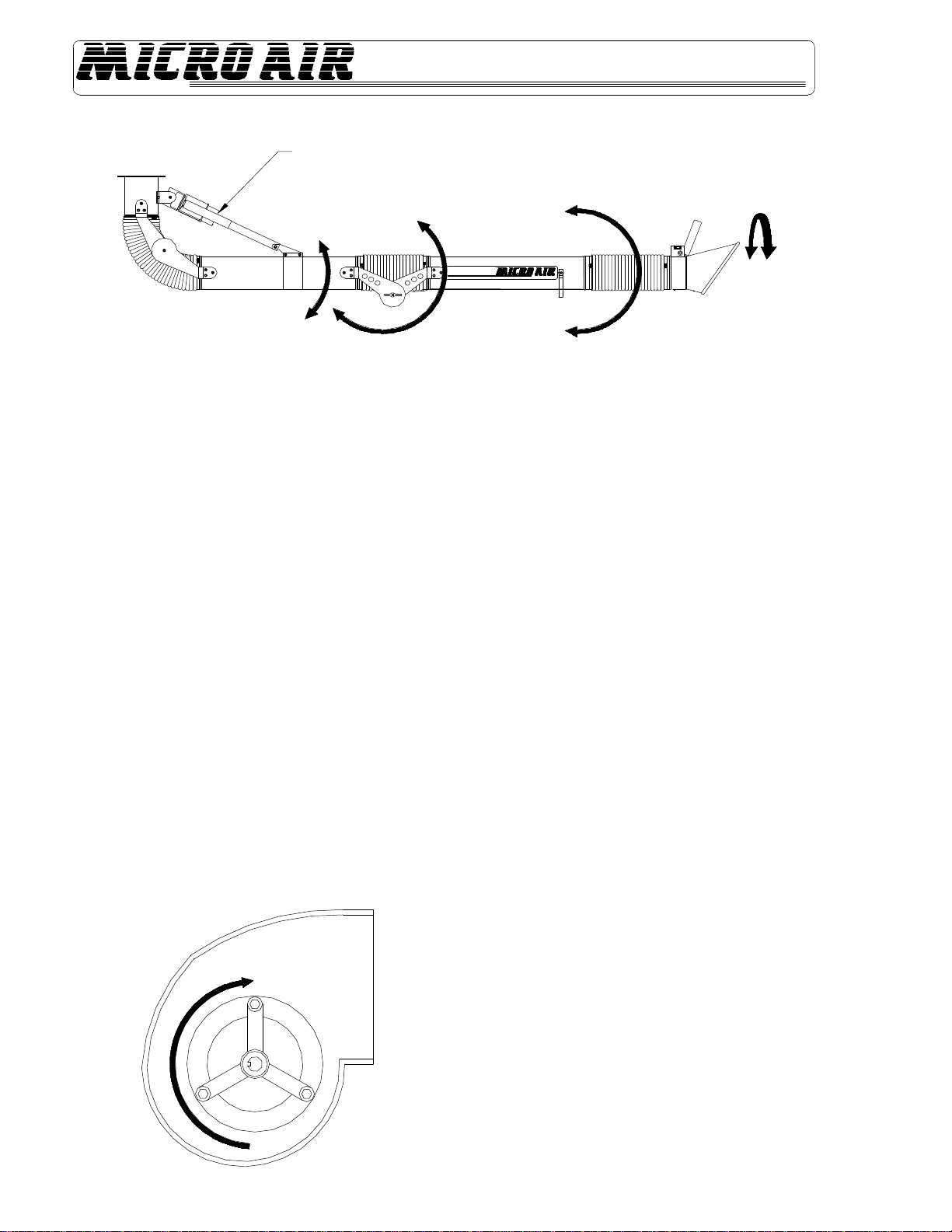
1. For motorized arm systems, the upper arm section can
be raised and lowered by depressing the toggle switch,
located on top of the remote switch control box, located
near the hood. The linear actuator has limit switches that
override the toggle switch when the arm exceeds the
retracted or extended length of the actuator.
2. Grasp the nozzle handle and lift the lower arm section up
and down. If the middle joint seems too tight, loosen the
two wingnuts that hold the joint together. If the arm has
trouble maintaining a position, hand tighten the wing nuts.
3. The nozzle-joint section can be manipulated up, down and
rotated. The joints are located inside the flexible hose
nearest the nozzle. If the joints are too loose or tight,
simply remove the hose clamp at the nozzle, gaining
access to the joints, and adjust as needed. (See FIG. 6.)
4. To operate blower, depress the fan switch located on the
remote switch control box to ON. The blower motor will
activate via a motor relay located inside the electrical
control box.
5. Be sure to check for proper blower rotation. If blower is
rotating backwards, interchange L1 and L2. (See FIG. 7.)
6. Activate the lamp located inside the nozzle by depressing
the lamp switch located on the remote switch control box.
ACTUATOR (OR RIGID PIPE)
90° UP
45° UP
20° UP
90° DOWN
45° DOWN
20° DOWN
7. The damper lever near the nozzle can be rotated 90° to
adjust inlet air velocity.
PRESSURE SWITCH ADJUSTMENTS
1. Make sure filters and pre-filters are installed in unit.
2. The pressure switch is preset at the factory to indicate
(light on) dirty filters, but may need readjustment due to a
desire for earlier or later filter changes, a different
combination of filters, or because the set point shifted
during shipping. To readjust the switch, remove the hole
plug in the side of the unit for access to the adjustment
screw. Turn the unit on and place a piece of cardboard
over the hood covering about 80-85% of the intake. With
a standard screwdriver, turn the adjustment screw
clockwise until the light goes off, or
counterclockwise until the light comes on.
3. For more time between filter changes (less airflow), cover
slightly more of the hood, and for less time between filter
changes (more airflow), cover less of the hood.
CHANGING FILTERS
CAUTION: ALWAYS MAKE SURE THAT THE UNIT IS TURNED
OFF BEFORE CHANGING FILTERS OR SERVICING THE UNIT.
1. The MAE 2200 is equipped with a filter change light, which
indicates when a filter needs to be replaced. If the differential
pressure has been set properly, the light signals the need for
examination of the filters.
2. When the light comes on, turn the unit off and remove the
pre-filter only. Replace with a new pre-filter, making sure that
the air flow directional arrow is pointed toward the outlet end.
Turn the unit back on. If the filter change light is off, then the
unit is operating properly.
3. If the filter change light fails to go out after replacing the pre-
filter, then the media bag filter may also need to be replaced.
4. Visually inspect the bag filter. If the pockets are loaded with
dirt, then remove the filter from the channel and insert a new
filter.
5. Start the unit. The filter change light should be off and the unit
operating properly.
FIG. 7
5
MAE2200 ®
UNITS WITH HEPAOR CHARCOAL
OPTIONS
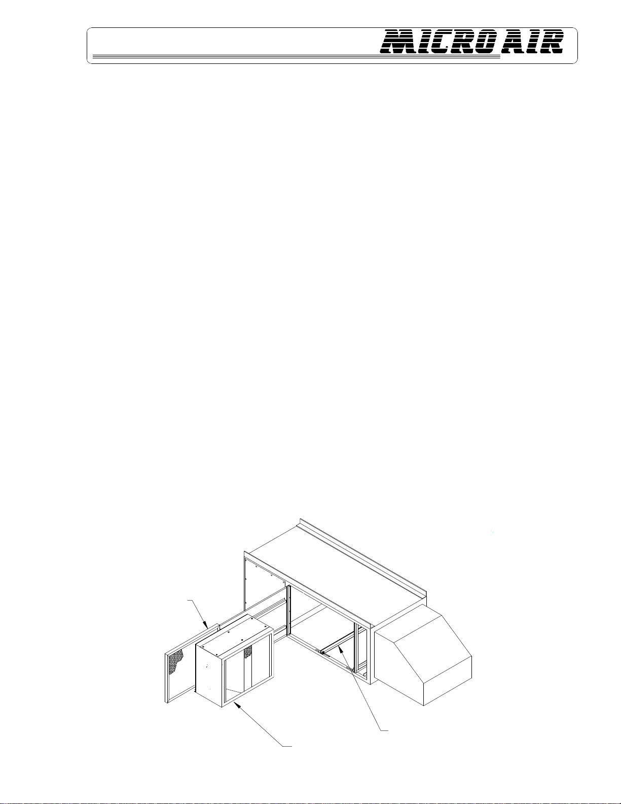
1. On units with optional Hepa or charcoal filters, an
adjustable filter track kit is used to complete the seal of
these filters to the filter stop, (see FIG. 8.) If the unit was
ordered with either a Hepa or charcoal filter, this adjustable
filter track kit was included with the unit. If a Hepa or
charcoal filter is ordered as an after market item, the
adjustable filter track kit should be ordered as well. Order
Part No. 30178-01 for each Hepa or charcoal filter initially
used.
2. Each filter track kit is supplied with two adjustable filter
tracks, four carriage bolts and four nuts. The corner
braces inside the MAE2200 unit are slotted. Position the
Hepa or charcoal filter in the unit up against the picture
frame filter stop at the blower end of the unit. Position the
adjustable filter track at the front (air inlet end) of the filter
in the inverted T position. (See FIG. 8.)
3. Install a carriage bolt in each of the two slots on either side
of the bottom of the unit. Push the carriage bolts towards
the front of the filter and through the holes provided in the
adjustable filter track.
4. Put a nut on each bolt, but do not tighten.
5. Repeat Steps 3 and 4 for the top adjustable filter track.
6. Use the two adjustable filter tracks to push the filter snugly
against the filter stop. Tighten the nuts on all four carriage
bolts.
7. If a second filter (Hepa or charcoal) is used in the unit,
repeat Steps 3, 4 and 5 for the leading filter. Push the
second filter snugly against the first using the adjustable
filter tracks and tighten the nuts. The second filter should
be resting on the adjustable filter track on both ends.
Because the bolts on the adjustable filter track between a
Hepa and charcoal filter combination may interfere with
the ends of the Hepa filter, the bolts for a middle filter track
may be omitted.
GENERAL MAINTENANCE-ARM(S)
1. Occasionally check the condition of the flexible hose for
any opening that will allow air to flow through. For
replacement, see Parts List.
2. Check the linear actuator for any debris that may have
settled along screw drive. Listen for any abnormal gear
noises during operation. No lubrication is required.
3. Periodically inspect the internal spring section at the
middle joint for debris or damage. Replace if needed.
4. Periodically inspect hardware for loose nuts and bolts
around the swivel base areas. Tighten if needed.
5. Periodically inspect all wiring for loose connections and
cracked or cut insulation. Replace as needed.
GENERAL MAINTENANCE –
MAE2200
1. Occasionally check the condition of the drive belt for
tightness and wear.
2. Check the blower bearings for unusual wear, and the
blower wheel for debris and dirt. Clean when necessary.
3. Check the wiring for loose connections or cracked
insulation.
4. If it should be necessary to replace the motor, it is much
easier to first remove the end panel of the unit for access
to the motor bolts.
5. No lubrication is required for the motor because it is a
permanent pre-lube design. Excessive dirt/oil should be
periodically removed.
FIG. 8
ADJUSTABLE FILTER TRACK
RCM FILTER KIT ASSY.
AFTER-FILTER
6
MAE2200
®
TROUBLESHOOTING CHART
CAUTION: BEFORE DISASSEMBLING THE UNIT OR DOING ANY
INSPECTION OF THE PARTS, MAKE CERTAIN THATTHE POWER HAS BEEN
CUT OFF, AND THE BLOWER HAS COME TO ACOMPLETE STOP. NEVER
RUN THE UNIT WITH THE ACCESS DOOR OPENED OR REMOVED.
PROBLEM POSSIBLE CAUSE REMEDY
Unit Fails to Start Dead Power Line Check Circuit and Switch
Blown Fuse Replace Fuse
Loose Wire in Terminal Box Reconnect Wire
Burned Out Motor Replace Motor
Unit Runs Slowly or Inadequate Wired for Wrong Voltage Check Input Voltage
or Improper Rotation Check Wiring Diagram
Dirty Filters Replace Filters
(See Changing Filters Section.)
Obstruction in Hose/Arm Assembly Reach into Hood and Remove
Obstruction
Mist Coming from Exhaust Dirty Disposable Filters Replace Filters
or Torn Filters
Air Bypass Around Filters Add Foam Seal to Seal Gaps
Vibration Loose Mounting Bolts Tighten Bolts
Foreign Object in Blower Remove Access Door and
Remove Object
Dirty Disposable Filters Replace Filters
(See Maintenance Section.)
Obstruction in Hose/Arm Assembly Reach into Hood and Remove
Obstruction
7
MAE2200 ®
ITEM PART NO. DESCRIPTION
1. 36071-01 Arm Grille
2. P2170 Lamp
3. P2168 Lamp Holder
4. P2847 Spring
5. P1342 Edge Guard
6. 36533-02 Nozzle Assembly
7. P2237 Foam Grip
8. 36025-01 Handle
9. 37070-01 Switch Box
10. P2719 Actuator Box
11. P2219 Rocker Switch
12. P200 Cotter Pin
13. P125 Washer
14. P2933 Rubber Seal
15. 36532-02 Collar Assembly
16. 36030-02 Mini Joint Half
17. 36535-01 Mini Joint Half
18. 36044-01 Damper Handle
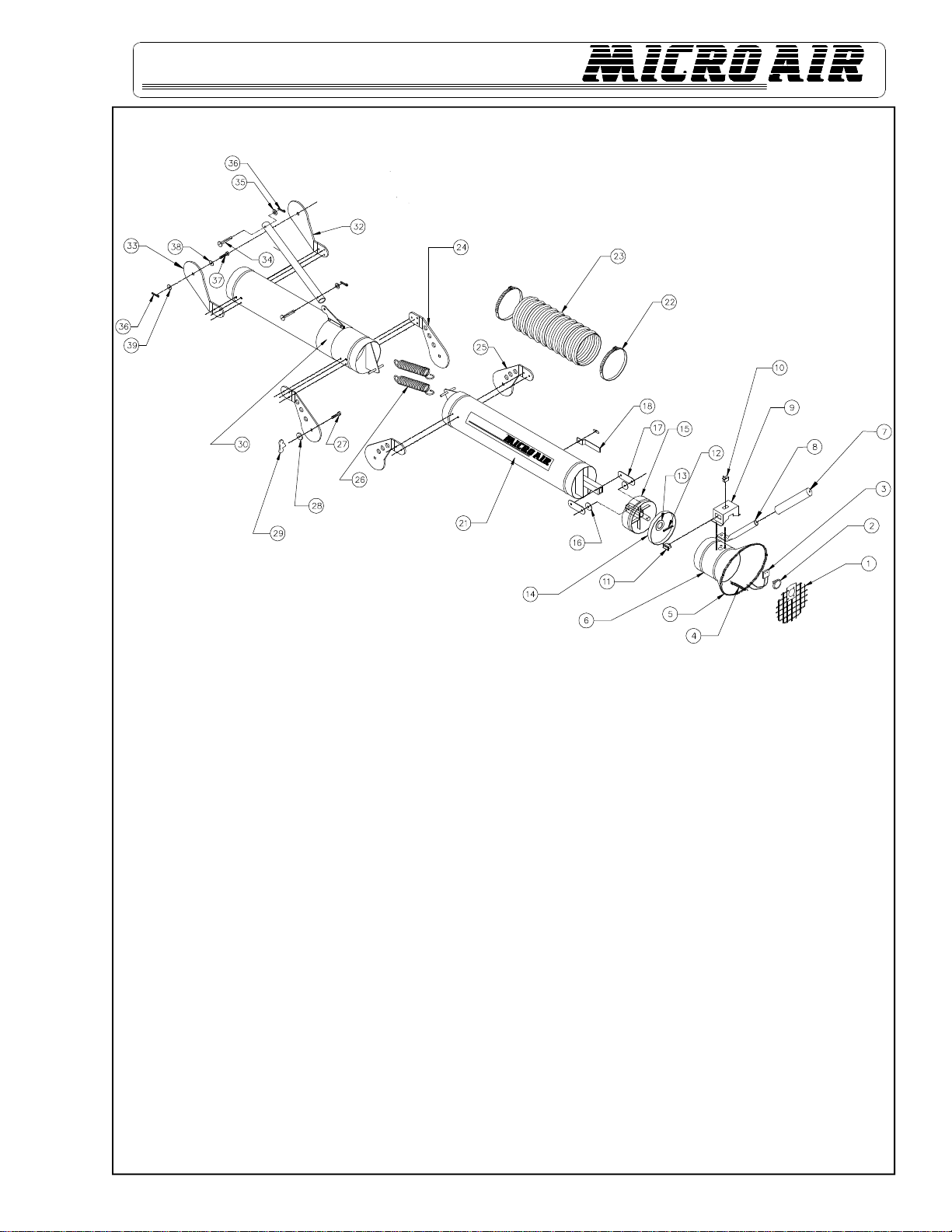
ITEM PART NO. DESCRIPTION
21. 36005-01 Steel Tube
22. P2232 Hose Clamp
23. P2617 Hose
24. 36020-01 Joint Half with Holes
25. 36020-02 Joint Half with Holes
26. P2615 Spring
27. P2673 Carriage Bolt
28. P2618 Thrust Bearing
29. P2619 Plastic Wing Nut
30. 36024-02 Adjustable Support Clamp
32. 36019-01 Joint Half
33. 36019-02 Joint Half
34. P2830 3/8” Clevis Pin
36. P2828 Cotter Pin
37. P2829 5/16” Clevis Pin
38. P2620 Nylon Washer
39. P233 5/16” Washer
MODEL MAE2200
PARTS LIST - ARM ONLY

MAE2200
Litho in U.S.A. 1997 Metal-Fab, Inc. Form No. L1241 10/99
6210
8
AIR CLEANERS
Products of Metal-Fab. Inc.
P.O. Box 1138
•
Wichita, KS. 67201
(316) 943 2351
•
FAX (316)943-2717
ITEM PART NO. DESCRIPTION
1. P1966 Motor
2. P1361 Blower
3. P1658 Blower Pulley
4. P1451 Belt
5. P2801 Motor Pulley
6. P1481 Lamp
7. P2800 Pressure Switch
8. 34083-01 Access Panel
9. 33287-06 Motor Access Panel
10. 33373-04 Filter Door
ITEM PART NO. DESCRIPTION
11. P1372 Latch - 2 ea.
12. 36038-02 Base Collar
13. 36019-01 Joint Half
14. 36019-02 Joint Half
15. 36031-01 Anchor Assembly
16. 36060-01 Nylon Ring
17. 36060-03 Mounting Ring
18. 36060-04 Nylon Ring
19. 36227-01 Plenum
MODEL MAE2200
PARTS LIST
®
®
Table of contents
Other MICRO-AIR Air Cleaner manuals

MICRO-AIR
MICRO-AIR OM 500 User manual

MICRO-AIR
MICRO-AIR WM 500 User manual

MICRO-AIR
MICRO-AIR M2150 User manual

MICRO-AIR
MICRO-AIR CLEAN AIR BOOTH User manual

MICRO-AIR
MICRO-AIR SC150 User manual

MICRO-AIR
MICRO-AIR XA34 Max User manual

MICRO-AIR
MICRO-AIR OM550DD User manual

MICRO-AIR
MICRO-AIR SC 150 User manual

MICRO-AIR
MICRO-AIR MT800 User manual

MICRO-AIR
MICRO-AIR MT1252 User manual


