MICRO-AIR OM 3510 User manual
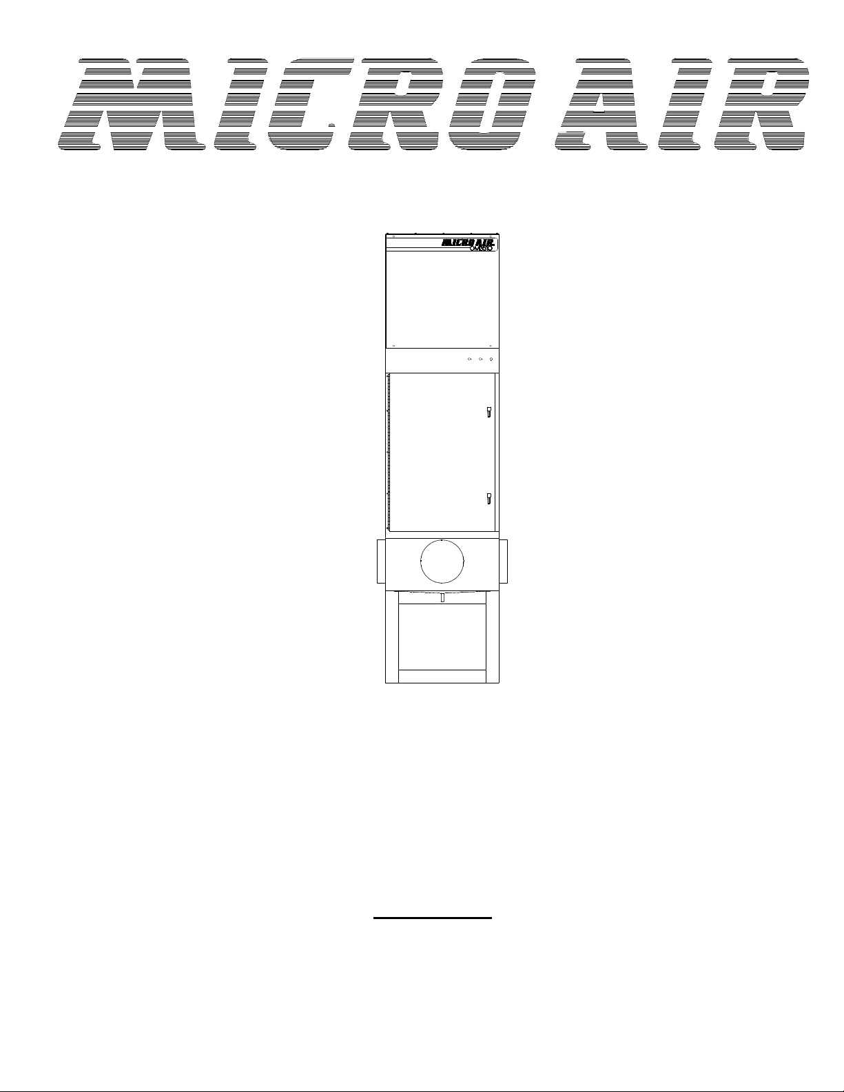
Model OM 3510
OWNER’S MANUAL
CAUTION
Read complete instructions before operating.
Please file for future reference.
AIR CLEANERS

2
OM3510
INSTALLATION INSTRUCTIONS
A. WALL MOUNT
1. Removefour5/16”boltsfromsidesofcabinetneartopand
bottomofunit.
2. UseboltsremovedinStep1tosecurewallmountbracketstounit
as shown in FIG. 1.
FIG.1
FIG.2
MODEL OM 3510 SPECIFICATIONS
Inputvolts: 120/208-230/460/575v,60Hz
Maxcurrent: 20Amps(at120V,1 ½HP,singlephase)
5.2amps (at208-230V,1½HP,3phase)
2.6amps(at 460V, 1½ HP, 3phase)
6.8Amps(at208-230V2HP,3phase)
3.4Amps(at460V, 2 HP,3 phase)
9.6Amps(at208-230V, 3HP,3phase)
4.8Amps (at460V, 3HP,3 phase)
3.9Amps (at575V, 3HP,3 phase)
Motor: 1 ½ HP TEFC
2 HP TEFC
3 HP TEFC
Dimensions: 81” h X 26”w X 26”l
102” h X 26”w X 26”l W/ Stand
ShippingWt: 340lbs
ActualWt: 310lb*
*Add35lb.percharcoalmoduleasoption
PACKAGE CONTENTS
1 Ea. OM3510 Unit
1 Ea. Owner’sManual
PRE-OPERATING INSTRUCTIONS
1. Cutbandingmaterialandremovecardboardandplasticfromunit. Remove
unitfromshippingskid.
2. Inspectunitforshippingdamageandreportanydamagetofreightcompany.
3. Locateaninstallationsitethatwillprovideforthefollowing:
l Asolidstructure,capableofsupportingtheweightoftheunit.
l Threefeetofunobstructedexhaustspacefromtheoutletoftheunit.
l Easyaccesstoservicepanelsandunitinlet. Asnearaspossibletothe
sourceofoilmistunittobecaptured.
4. Marklocationofmountingholesonthesurfacetowhichunitistobe
mounted. SeeFIG. 2forholepattern. Drillholesthataresized
correctlyforholepatterninmountinghardware.
5. PositiontheOM3510wallmountbracketholesovertheholes
locatedonthestructureinStep4. Use3/8”x2”lagboltsor3/8”
boltsandnutstosecureOM3510tostructure.
CAUTION: The size and weight of the OM 3510 requires two persons or
mechanical means to lift and hold during mounting.
6. Connectunittooilmistsourceusingaducthavingthesame
diameterastheinletoftheunit. Theductmaybeflexiblehoseor
formedsheet metal. Maximumflowwillbeobtainedwithminimum
bendsinduct. Tocontainoilthatwillcollectontheinsideoftheduct,
theductmustbesealed. SlopingtheducttowardtheOM3510will
assistflow. Usehoseclampsofsheetmetalscrewstoattachductto
unit.
NOTE: Optionalhoseadaptersareavailableforconnectionto6”and8”
diameterhose. UsePartNo.34096-01for6”dia..AndPartNo.34096-02
for8”dia. Attachadaptertoplenumcollarwithsheetmetalscrewsand
sealwithRTVsealant.
C. FLOOR MOUNT
NOTE: Theoptionalbaseassembly(PartNo.38046-02)isrequiredfor
floormountinstallation.
1. locateaninstallationsiteonalevelsurfacethatwillmeetthe
requirementslistedinStep3ofthewallmountinginstructions.
2. Setthebaseinplaceandlifttheunitontothebase.
CAUTION: The size and weight of the OM 3510 requires two persons and/or
mechanical means to lift and hold during mounting.
NOTE: Youmaywanttoboltthebasetothefloor.
3. ConnecttheunittotheoilmistsourceasexplainedinStep6ofthe
wallmountinginstructions.
D. CEILING MOUNTING
NOTE: Theoptionalceilingmountingkit(PartNo.38049-02)isrequired
forceilingmountinstallation.
1. Removethetwo5/16”boltsfromthesideofthecabinetattheoutlet
end.
2. UsetheboltsremovedinStep1tosecuretheceilingmountbrackets
totheunitasshowninFIG. 3.

3
OM3510
FIG.3
3. Locateaninstallationsitethatwillmeettherequirementslistedin
Step3ofthewallmountinginstruction.
4. Firmlysecurefourlengthsof3/8”threadedrodtoafirmstructural
support. Spacerodstomatchpatternmadebyholesintopof
ceilingmountbrackets.
5. Threadonenutontoeachrod.
CAUTION: The size and weight of the OM 3510 requires two persons or
mechanical means to lift and hold during mounting.
6. Raiseunituptothreadedrodsandinsertrodsthroughceiling
mountbrackets. Threadasecondnutontoeachrodfrombelow
bracket.
7. Levelunitbytighteningnutsagainstceilingmountbracket.
8. Threadathirdnutontoeachrodandtightenagainstsecondnutto
preventlooseningofnutsduetoVibration.
9. ConnecttheunittotheoilmistsourceasexplainedinStep6of
thewallmountinginstructions.
OIL DRAINAGE
NOTE: Should captured oil be disposed of, make sure to follow local
codes.
Provisionfordrainingoilfromunitisprovidedforbya1”N.P.T.pipe
couplingonthebottomoftheunit. Drainagecanbepipedtoacentralcollection
systemorcollectedinabucketplacedundertheunit. Inallcasesashut-off
valveordraintrapisrequiredtopreventairbypassthroughthedrainopening.
OneofthedrainsystemsshowninFIG. 4shouldbeused. Drainconnections
andlinesarenotprovided.
NOTE: Ifashutoffvalveisinstalledinthedrainsystem,theunitmustbe
emptiedregularlytopreventoilfromoverflowingintotheintakeduct.
FIG.4
AIR FLOW ADJUSTMENT
The OM 3510 is equipped with variable diameter pulleys on the motor and blower
to allow the air flow to be adjusted to the installation requirements. The pulleys are set
for maximum air flow at the factory. The air flow rate can be reduced as follows:
1. Remove motor compartment access cover. Be careful to avoid tearing gasket
material between door and cabinet.
2. Remove belt.
3. Loosen pulley adjustment set screw on motor pulley and screw adjustable shive
out away from fixed shive. Tighten set screw onto flat of fixed screw (see FIG.
5).
4. Adjusting the motor pulley may require a size larger or smaller belt, depending on
the application.
5. Replace belt and check belt tension. Proper tension should be between ½” and
¾” deflection when belt is squeezed with normal pressure between fingers.
6. Replace motor compartment access cover.
7. Recheck for correct current draw of motor
NOTE: All filters and panels must be on unit and door closed for current
measurements of motor.
FIG.5
ELECTRICAL CONNECTIONS
1. Conduit electrical connections should be made by a qualified electrician, and
must comply with local electrical codes.
CAUTION: Be sure that the designated circuit breaker is off until all wiring
has been completed.
NOTE: It is recommended that a properly sized motor starter / protector be used in the
supply circuit for 208-240V/460V/575V units. 120V units have thermally protected
motors with on/off switches.
2. Make electrical connections as shown in wiring diagram to the wires protruding
from the conduit on the side of the unit.
3. Check blower for proper rotation direction. Blower should rotate clockwise when
viewed from the pulley end. If the blower rotates backwards, interchange two of
the motor supply connections.
4. Check current draw of motor. Do not exceed AMPs specified.
PRE-OPERATION CHECKLIST
Before placing unit in service, check the following items:
lCheck blower drive belt for proper tension. (Belt should deflect approximately
3/4” when firm pressure is applied midway between the pulleys.)
lCheck that motor, blower, and drive pulleys are mounted securely.
lMake sure that both corners of every pocket in the filter bag is supported by the
filter support rods and that filter support rods are fully engaged in their support
brackets.
lAir flow direction arrows on the oil impingers / pre-filters must point toward the
blower.
lCheck that air intake and oil drain connections are air or oil tight.
lMake sure that all access panels, removed during installation, are replaced and
the filter access door is closed.
Unit is now ready to be placed in service.
4
OM3510
OPERATION
A. PRESSURE SWITCH ADJUSTMENTS
1. The pressure switch is preset at the factory to indicate (light on)
dirty filters, but may need readjustment due to a desire for earlier
orlaterfilterchanges,adifferentcombinationoffilters,orbecause
thesetpointshiftedduringshipping. Thepressureswitchisalso
orientationsensitive. Toreadjusttheswitch,removethehole
pluginthesideoftheunitforaccesstotheadjustmentscrew.
Makesurefiltersandpre-filtersareinstalledinunit. Turntheunit
onandplaceapieceofcardboardovertheintakecoveringabout
80to85%oftheintakearea. Ona3-inletsystem,cover
entirelytwoinletsandalittlemorethanhalfoftheareaofthethird
inlet. Withastandardscrewdriver,turntheadjustmentscrew
clockwiseuntilthelightgoesoff,orcounterclockwiseuntilthe
lightcomeson.
2. Formoretimebetweenfilterchanges(lessairflow),cover
slightlymoreoftheopening,andforlesstimebetweenfilter
changes(moreairflow),coverlessoftheopening.
B. GENERAL MAINTENANCE
1. Occasionallychecktheconditionofthedrivebeltfortightness
andwear.
2. Checktheblowerbearingsforunusualwearandtheblower
wheelfordebrisanddirt. Cleanwhennecessary.
3. Checkthewiringforlooseconnectionsorcrackedinsulation.
4. Nolubricationisrequiredforthemotorbecauseitisapermanent
pre-lubedesign. Excessivedirt/oilshouldbeperiodically
removed.
5. Makesureoilisdrainingeasilythroughdrainpipe.
C. CHANGING FILTER
CAUTION: Always make sure that the unit is turned off before
changing filters or servicing the unit.
1. TheOM3510isequippedwithafilterchangelight,or(optional)
MagnahelicGauge,whichindicateswhenafilterneedstobe
replaced. Ifthedifferentialpressurehasbeensetproperly,the
light,orgaugesignalstheneedforexaminationofthefilters.
2. Whenthelightcomeson,orgaugereadshighdifferential
pressure, turntheunitoffandremovetheimpingerandmesh
pre-filterfromtheunit. Washthesepre-filtersinadetergent
solutiontoremovedirtandoilresidue.
3. Rinsethepre-filtersthoroughlywithwater, shakedryand
replaceintheunitwithairflowdirectionpointingtotheblower
(replacepleatedpre-filtersifinuse).
4. Ifthefilterchangelightfailstogoout,orthegaugecontinuesto
readhighdifferentialpressure,afterreplacingthepre-filter,then
theoilbagfiltermayalsoneedtobereplaced.
5. Visuallyinspectthebagfilter. Ifthepocketsareloadedwithoil
anddirt,thenremovethefilterfromthechannelandinsertanew
filter.
6. Starttheunit.Thefilterchangelightshouldbeoff,orthegauge
readslowdifferentialpressureandtheunitshouldbeoperating
properly.
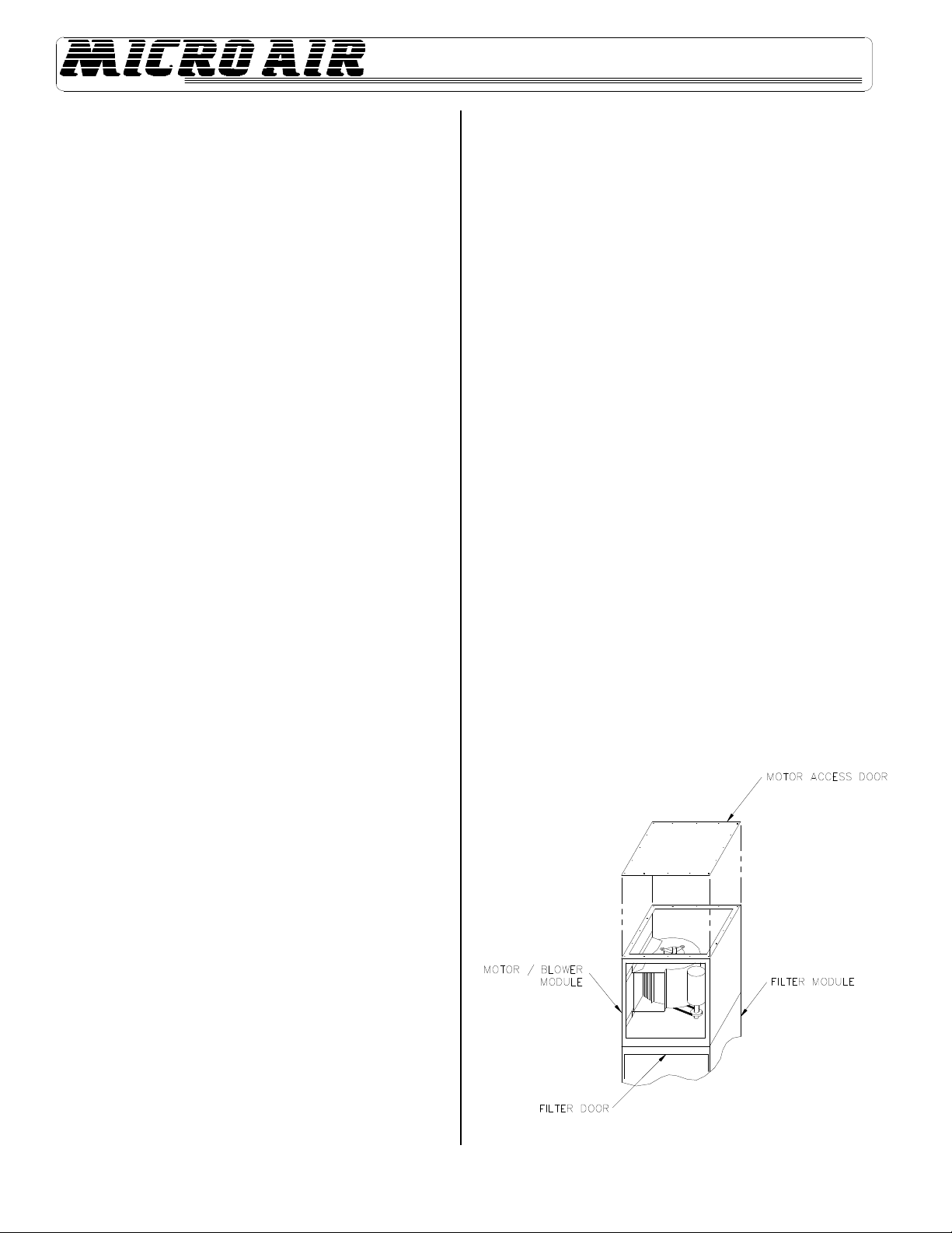
INSTRUCTIONS FOR SIDE DISCHARGE
BLOWER EXHAUST ON OM 3510
CAUTION: Read instructions completely before making changes.
1. TheOM3510motor/blowermodulecanberotatedsothatexhaustair
exitsfromthesideoftheunit. Beforerotatingmotor/blowermodulebe
surethatallinputpowerisdisconnectedandunitisturnedoff.
2. Removemotoraccessdoorandexhaustgrille.
NOTE: Careisrequiredwhenremovingthepaneltoprotectthebloweroutlet
gasket.
3. Remove5/16”hexboltsandwashersthatsecuremotor/blowermodule
tofiltermodule.
4. Rotatemotor/blowermodule90°asshownInfigure 6.
5. Using5/16”hexboltsandwashersre-securemotor/blowermodule
withfiltermodule.
CAUTION: Due to relocation of internal components, some wiring
may be loose. Be sure to retain wires so they will not become loose in
air stream of blower inlet.
6. Reinstallmotoraccessdoorandexhaustgrille.
NOTE: Careisrequiredtoprotectbloweroutletgasket.
7. Reconnectinputpowerandturnuniton. Checkforproperairflowand
blowerrotations.
FIG.6
5
OM3510
FIG.7
UNITS WITH HEPA OR CHARCOAL OP-
TIONS FOR OM 3510
1. OnunitswithoptionalHEPAorcharcoalfilters,anadjustablefiltertrackkitis
usedtocompletethesealofthesefilterstothefilterstop(seefigures 7 &8).
IftheunitwasorderedwitheitheraHEPAorcharcoalfilter,thisadjustable
filtertrackkitwasincludedwiththeunit. IfaHEPAorcharcoalfilteris
orderedasanaftermarketitem,theadjustablefilertrackkitshouldbeordered
aswell. OrderPartNo.38036-01.
2. Eachfiltertrackkitissuppliedwith:
(1) 1pc.Filtertrack
(1) 2pc.Supports
(2) 1pc.Handle
(3) 4pc.Retainingbrackets
(1) 1pc.Doorstopbracket
(2) 3pc.Horizontalsupport
(3) 16pc.#8-32selftappinghexscrews.
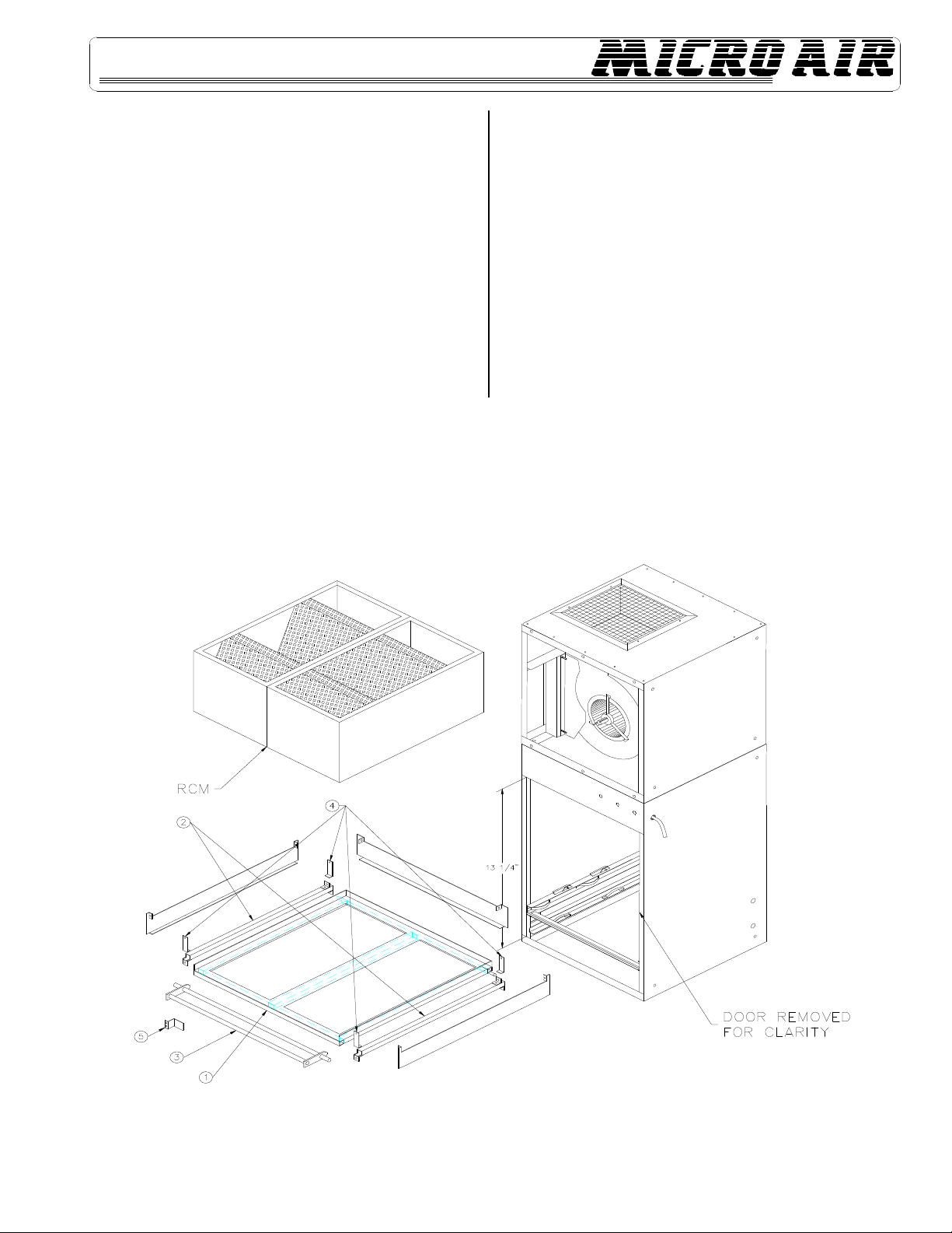
HEPA OR CHARCOAL AS SECOND MAIN FILTER
1. Placesupports(2)incabinetatadimensionof13¼”andsecurewithself
tappingscrew.
2. Placetrack(1)incabinetsoitrestsuponsupportsand½”diameterpinis
locatedbehindbracketsonsupports.
3. Placehandle(3)onsupportssothatitrestsinnotches.
4. Lock½”diameterrodsonhandleandtrackinplacewithbrackets(4)and
selftappingscrews.
5. Placehandlestopbracket(5)atadimensionof15½”andsecurewithself
tappingscrews. Thisistokeephandlefromrotatingpast90°andallowing
filtertoloosen.
6. Horizontal support (6) is not used in this case.
6
OM3510
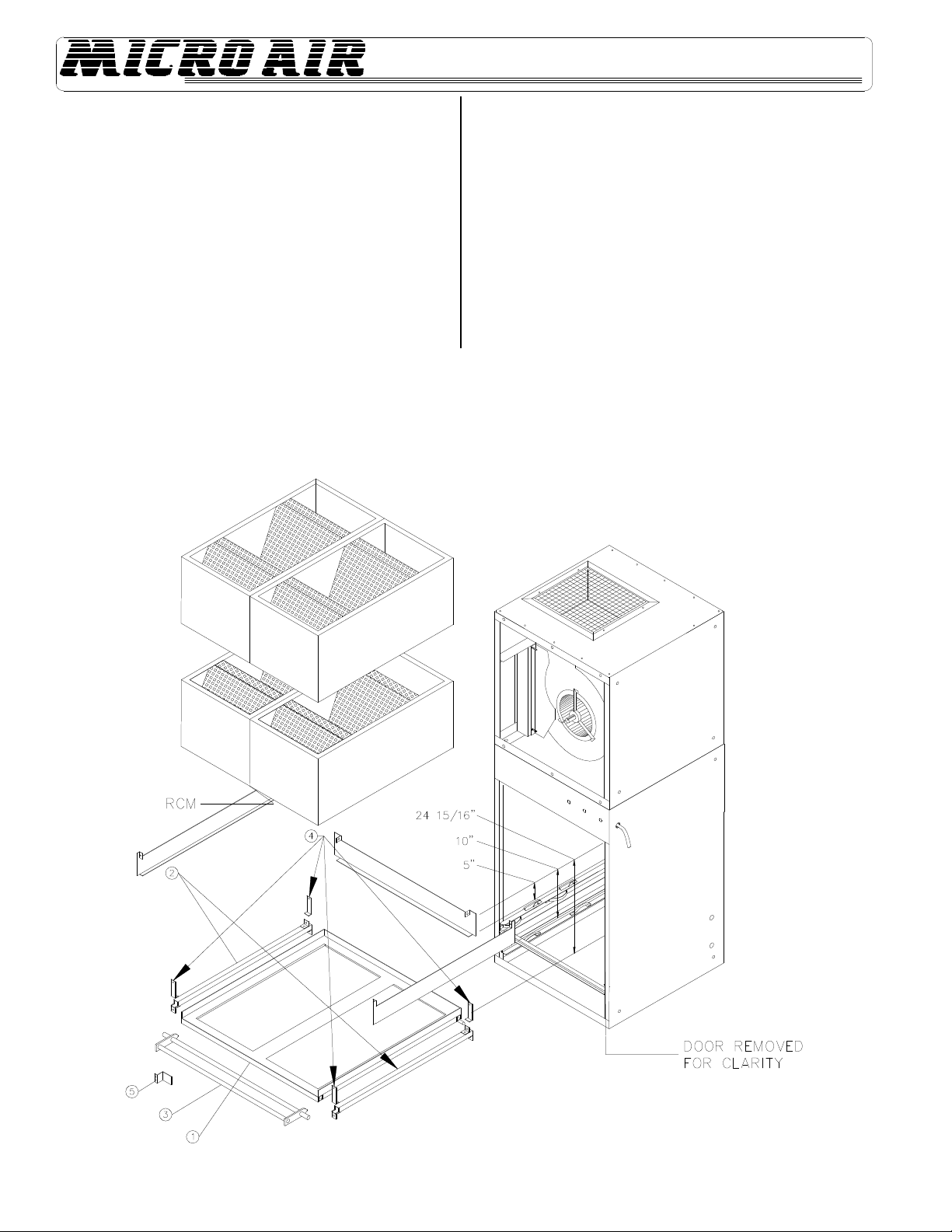
HEPA OR CHARCOAL AS FIRST AND SECOND MAIN FILTERS
1. Place supports (2) in cabinet at a dimension of 24 15/16” and
secure with self tapping screws.
2. Place track (1) in cabinet so it rests upon supports and ½”
diameterpinislocatedbehindbracketsonsupports.
3. Placehandle(3)onsupportssothatitrestsinnotches.
4. Lock½”diameterrodsonhandleandtrackinplacewithbrackets(4)and
selftappingscrews.
5. Placehandlestopbracket(5)at dimensionof27”andsecurewithself
tappingscrews. Thisistokeephandlefromrotatingpast90deg.and
allowingfiltertoloosen.
6. PlaceHorizontalSupports(6)2pc.onsidesofthecabinetatadimensions
of10”and(6)1pc.onrearofcabinetat5”andsecurewithselftapping
screws.
FIG.8
7
OM3510
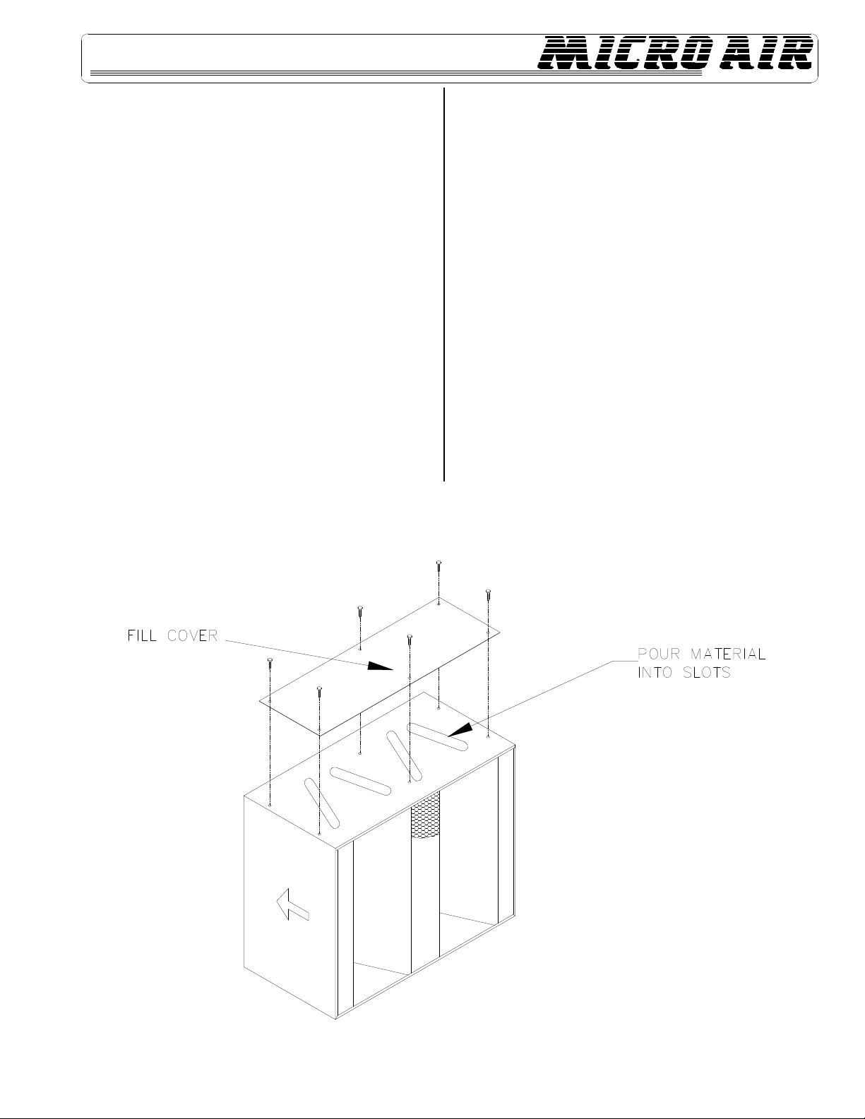
FILLING OF RCM MODULES
1. Removebulkcharcoalorpurasorbfromshippingcartonbyremovingplastic
bagswithincarton.
2. setmoduleonlevelsurface. Removefillcoverbyremovingsix10-32
phillipsheadscrews,thatsecurecover. Setcoveraside(seefigure 9).
3. Opentheplasticbagbyremovingthetape,holdingclose. Pourthematerial
fromtheplasticbagintothemodulethroughtheslots. Itmaybenecessary
toslightlyshakethemoduletoassureanevenfill. Excessmaterialmaybe
savedbyresealingtheplasticbag.
NOTE: Slowpouringwillminimizedustthatwillbepresentduringpouring.
4. Afterfillingmodule,discardplasticbagandreinstallfillcoverremovedin
step2.
NOTE: TheOM3510requirestwomoduleswhenusedasasecondmainfilter
andfourmoduleswhenusedasafirstandsecondmainfilter.
5. WithFiltertrackinplaceandhandlepulledoutawayfromcabinetloadRCM
/HEPA modulesintotrack.
NOTE: Makesuremodulesareseatedproperlyintotrackandstackedevenly.
6. Withfiltersinplacerotatehandle90°andlockfiltermodulesinplace.
FIG.9
8
OM3510
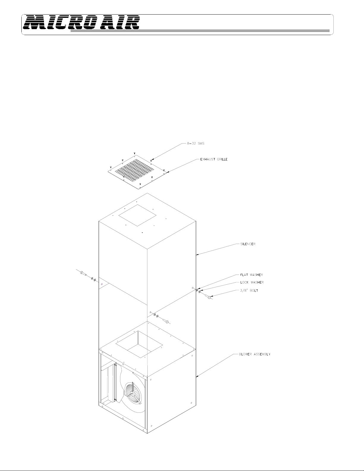
OPTIONAL SILENCER INSTALLATION
1. RemoveExhaustGrillefromunitasshowninFIG. 10.
2. SlideSilencer overBlowerAssembly.
3. AlignholesfromSilencerwiththoselocatedonsidesoftheBlowerAssembly.
4. AttachSilencertoBlowerAssemblyusing3/8”bolt,lockwasher,&flatwasher.
5. CenterExhaustGrilleoverholeinSilencer&attachusing8-32selftappingmachinescrews.
FIG. 10
9
OM3510
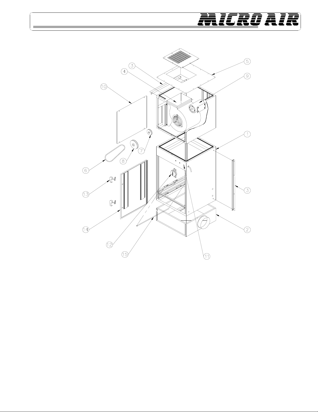
ITEM PART NO. DESCRIPTION ITEM PART NO. DESCRIPTION ITEM PART NO. DESCRIPTION
1. 38071-01 Cabinet Weldment 8. P1710 4.95" Blower Pulley NOT SHOWN 38046-01 Optional Floor Stand
2. 38024-01 Inlet Plenum P1974 5.93" Blower Pulley NOT SHOWN 38050-01 Silencer
3. 38049-01 Wall Bracket (2 ea. required) P1711 6.93" Blower Pulley NOT SHOWN P1585 70% Washable Pre-Filter
38049-02 Ceiling Bracket (2 ea. required) P3218 7.95" Blower Pulley NOT SHOWN P1586 96% Washable Pre-Filer
4. P3498 Blower (Standard) P3183 9.95" Blower Pulley NOT SHOWN P1461 Pleated Pre-Filter
5. 38010-01 BlowerAccessPanel P3540 12.00" Blower Pulley NOT SHOWN P1475 AluminumMeshPre-Filter
6. P1495 42" Belt 9. P3545 1 1/2 HP 115V Single Phase NOT SHOWN P1799 Baffle Impinger
P3207 43" Belt P3546 1 1/2 HP 208-230/460V. 3 Phase NOT SHOWN P1411 Pleated Pre-Filter 4"
P3182 44" Belt P1966 2 HP 208-230/460v. 3 Phase NOT SHOWN P1455 95% HEPA Filter
P3198 45" Belt P3495 3 HP 208-230/460v. NOT SHOWN P2101 99.97% HEPA Filter
P3213 46" Belt P2813 3 HP 575V. 3 Phase NOT SHOWN P1439 55% Long Bag
P3195 47" Belt 10. 38011-02 MotorAccessPanel NOT SHOWN P1442 95% Long Bag
P3548 48" Belt 11. P1429 Light (120V) NOT SHOWN P2179 95% Oil Mist Bag
P3550 49" Belt P1481 Light (208-230V, 460V, 575V) NOT SHOWN P2104 55% Duo Cube
P3549 52" Belt 12. P3505 PressureSwitch NOT SHOWN P2116 95% Duo Cube
7. P2105 1 1/2 HP, 5/8" Shaft, Motor Pulley 13. P1372 Door Latch (2 ea. required) NOT SHOWN P1460 95% short Bag
P3578 2 HP, 5/8" Shaft, Motor Pulley 14. 38022-01 Filter Door NOT SHOWN P2817 95% Short Oil Mist Bag
P3579 2 HP, 7/8" Shaft, Motor Pulley 15. P3214 Gasket Material (Specify Length) NOT SHOWN P3002 MaxGridPanelFilter
P2140 3 HP, 7/8" Shaft, Motor Pulley NOT SHOWN P2250 Magnahelic Gauge NOT SHOWN P3008 4” Mist-xfilter (Chevron)
NOT SHOWN 33740-00 RCM Module

10
OM3510
OM 3510 Wiring Diagram

11
OM3510
NOTES:

12
OM3510
TROUBLESHOOTING CHART
CAUTION:
Before disassembling the unit or doing any inspection of the parts, make certain that the power has been cut off and the
blower has come to a complete stop. Never run the unit with the access door open or removed.
Problem Possible Cause Remedy
UnitFailstoStart Dead Power Line ChecktheCircuitandSwitch
BlownFuse ReplaceFuse
LooseWireinTerminalBox ReconnectWire
BurnedOutMotor ReplaceMotor
UnitRunsSlowlyor WiredforWrongVoltage CheckInputVoltage
InadequateCaptureVelocity orImproperRotation CheckWiringDiagram
DirtyFilters ServiceFilters
(SeeChangingFiltersSection)
ObstructioninHose/Arm ReachintoHoodand
Assembly RemoveObstruction
PulleysSetForStatic AdjustorChangePulleys
Vibration LooseMountingBolts TightenBolts
ForeignObjectsinBlower RemoveAccessDoorand
RemoveObjects
DirtyDisposableFilters ServiceFilters
ObstructioninHose/Arm ReachintoHoodand
Assembly RemoveObstruction
UnittrippingBreaker CurrentDrawofMotor AdjustorChangePulleys
ToHigh
AIR CLEANERS
Products of Metal_Fab. Inc.
P.O. Box 1138 • Wichtia, Ks 67201
(316) 943-2351 • FAX (316) 943-2717
© 1997 Metal-Fab, Inc. Form No. L1470 9/99
6169
Litho in U.S.A.
®
Table of contents
Other MICRO-AIR Air Cleaner manuals

MICRO-AIR
MICRO-AIR MT800 User manual

MICRO-AIR
MICRO-AIR MAE2200 User manual

MICRO-AIR
MICRO-AIR WM 500 User manual

MICRO-AIR
MICRO-AIR SC150 User manual

MICRO-AIR
MICRO-AIR WC2500 User manual

MICRO-AIR
MICRO-AIR MT1252 User manual

MICRO-AIR
MICRO-AIR MX3510 User manual

MICRO-AIR
MICRO-AIR OM 500 User manual

MICRO-AIR
MICRO-AIR OM550DD User manual

MICRO-AIR
MICRO-AIR XA34 Max User manual


Popular Air Cleaner manuals by other brands

Momax
Momax Ultra-Air Plus instruction manual

Honeywell
Honeywell 60001 - Enviracaire Grade Air Purifier owner's manual

TEFAL
TEFAL INTENSE PURE AIR CONNECT PU4085 Series manual

Ravanson
Ravanson MAC-12000 user manual

Sensede
Sensede SIGNATURE Series operating instructions

Clean Air Way
Clean Air Way R-CLEAN 200 quick start guide


