MICRO-AIR OM 500 User manual

Model OM 500
OWNER’S MANUAL
CAUTION
Read complete instructions before operating.
Please file for future reference.
AIR CLEANERS ®
MODEL OM 500 SPECIFICATIONS
Input Volts: 120VAC,60Hz,SinglePhase
208-230/460 VAC, 3-Phase (Optional)
Max.Current: 120VAC 10.4Amps
208-230VAC 3.2Amps
460VAC 1.6Amps
Motor: 3/4 HP TEAO
1HPTEAO3-Phase(Optional)
AirFlow*: 6”Inlet 665 CFM (3387 FPM)
8”Inlet 800 CFM (2292 FPM)
Dimensions: 49”Hx26”W x 14” D (withoutwallbrackets)
ShippingWeight: 175lbs.
Actual Weight: 155lbs.
*Allair flows are tunnel tested readings.
PACKAGE CONTENTS
1ea. OM 500 Unit
2ea. Wall Mount Brackets
1ea. Owner’sManual
PRE-OPERATING INSTRUCTIONS
1. Cutbandingmaterialandremovecardboardandplasticfromunit. Removeunit
fromshippingskid.
2. Inspect unit for shipping damage and report any damage to freight carrier.
INSTALLATION INSTRUCTIONS
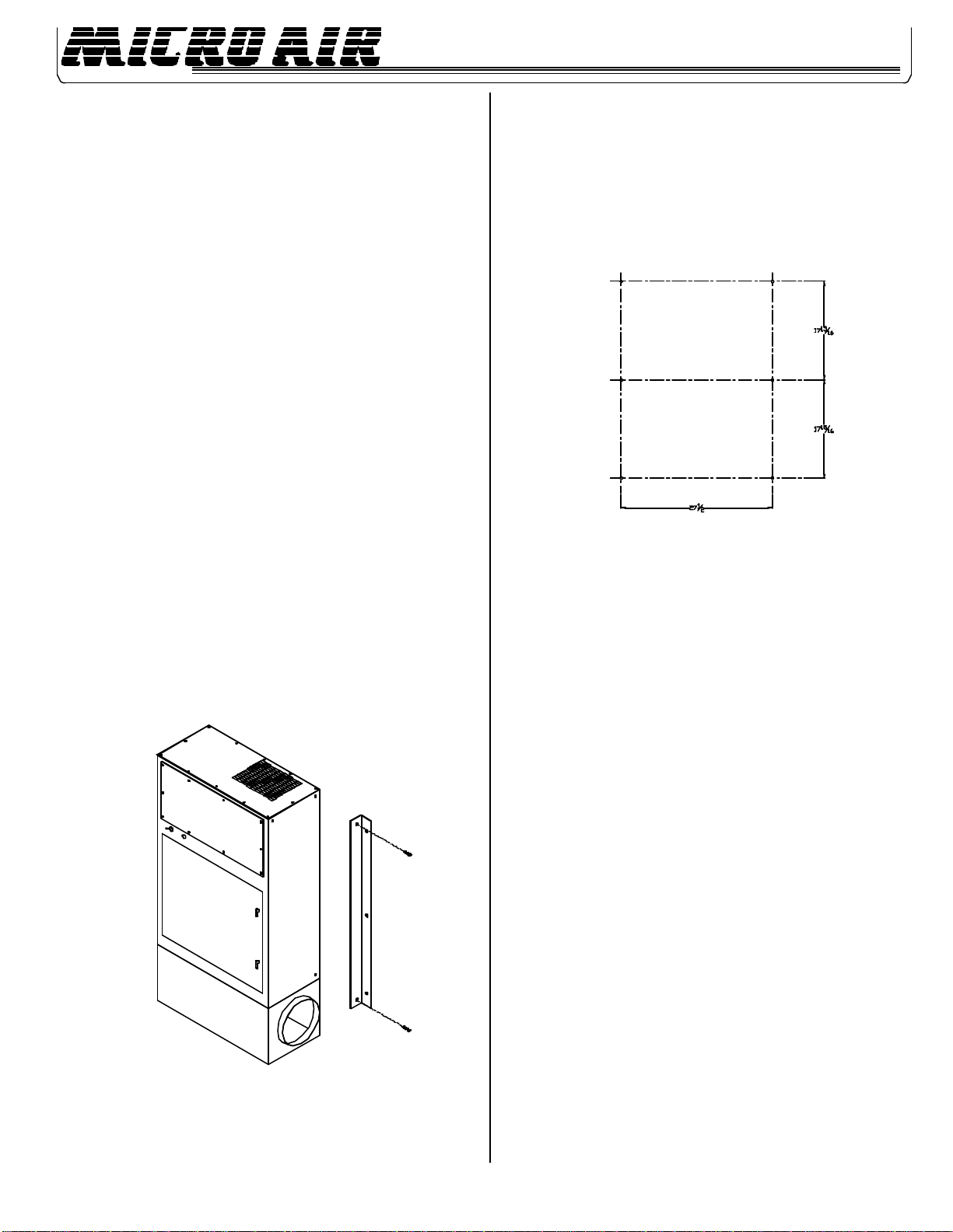
A. WALLMOUNT
1. Removefour5/16”boltsfromsidesof cabinet near top and bottom of unit.
2. Useboltsremoved in Step 1 to secure wall mount brackets to unit
as shown in FIG.1.
3. Locateaninstallationsitethatwillprovide for the following:
•Asolid structure, capable of supporting the weightof the unit.
•Three feet of unobstructed exhaust space from the outlet of the unit.
•Easyaccessto servicepanelsandunitinlet.
•Asnear as possible to the sourceof oil mist unit to becaptured.
FIG. 1
FIG. 2
4. Marklocationof mountingholesonthesurface towhichunitis to bemounted
(see Figure2 for hole pattern). Drill holes that are sized correctly for the
holepatterninmountinghardware.
5. PositiontheOM 500 wallmountbracketholes over theholeslocatedonthe
structureinStep4. Use3/8”x2” lag bolts or 3/8” bolts and nuts to secure
theOM500tostructure.
CAUTION:Thesize and weight of theOM500 requires two persons or
mechanicalmeanstoliftandholdduringmounting.
6. Connectunittooilmistsourceusingaducthaving the same diameter as
theinletoftheunit. The duct may be flexible hose or formed sheet metal.
Maximumflowwill be obtainedwithminimumbends in duct. Tocontainoil
that will collect on the inside of the duct, the duct must be sealed. Sloping
the duct toward the OM 500 will assist flow. Use hose clamps or sheet
metal screws to attach duct to unit.
NOTE: Optionalhoseadaptersareavailableforconnectionto6”and8”
diameterhose. UsePart No. 34145-01for6”diameter hose, andPartNo.
34145-02for8”diameterhose. Attachadaptertoplenumcollarwithsheet
metalscrewsand seal with RTVsealant.
B. FLOORMOUNT
NOTE: The optional base assembly (Part No. 38162-01) is required for floor
mountinstallation.
1. Locateaninstallation site on alevelsurfacethat will meet therequirements
listed in Step 3 of the wall mounting instructions.
2. Set the base in place and lift the unit onto the base.
CAUTION: Thesizeand weightof the OM500 requires twopersons
ormechanicalmeans to liftandhold during mounting.
NOTE: Youmay want to bolt the base tothe floor.
3. Connect the unit to the oil mist source as explained in Step 6 of the wall
mountinginstructions.
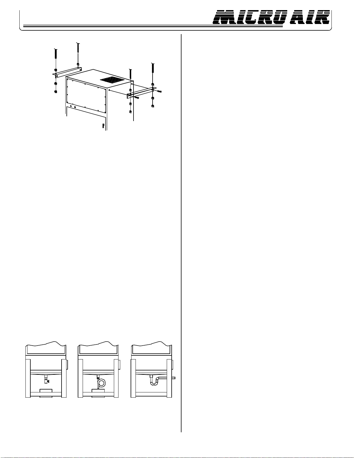
C. CEILINGMOUNTING
NOTE: Theoptional ceilingmountingkit (PartNo.38088-02) isrequiredfor ceiling
mountinstallation.
1. Remove the two (2) 5/16” bolts from the side of the cabinet at
2. Usethebolts removed in Step 1 to secure the ceilingmountbrackets to the
unitasshowninFIG.3.
2
OM500
3. Locateaninstallationsitethatwillmeettherequirementslisted in Step 3 of
the wall mounting instruction.
4. Firmlysecurefour lengths of 3/8”threadedrodto a firm structuralsupport.
Spacerodsto match patternmadebyholes in topofceilingmountbrackets.
5. Thread one nut onto each rod.
CAUTION: Thesizeand weightof the OM500 requires twopersons
or mechanicalmeans tolift andhold duringmounting.
6. Raise the unit up to threaded rods and insert rods through ceiling mount
brackets. Threadasecondnut onto each rod from below bracket.
7. Level unit by tightening the nuts against the ceiling mount bracket.
8. Thread a third nut onto each rod and tighten against the second nut to
preventlooseningof nuts due tovibration.
9. Connecttheunittothe oil mist source as explained in Step 6 of the wall
mountinginstructions.
OIL DRAINAGE
NOTE: Shouldcapturedoil be disposed of,makesure to follow local codes.
Provision for draining oil from unit is provided for by a 1” NPT pipe coupling on the
bottomoftheunit. Drainagecanbepipedtoacentralcollectionsystemorcollectedin
abucketplaced under the unit. In all cases a shut-off valve or drain trapisrequired to
preventairbypassthroughthe drain opening. One of thedrainsystemsshowninFig.
4 shouldbeused. Drainconnectionand lines are not provided.
NOTE: Shutoffvalve isinstalledin thedrainsystem,theunitmustbeemptied regularly
topreventoilfromoverflowingintotheintakeduct.
FIG. 3
ELECTRICAL CONNECTIONS
A. SINGLEPHASE 120VOLT
Becertainthat thesystemON/OFFswitchis intheOFFposition. Plug thepower
cordintothenearestoutletratedfor120volts.
B. THREE PHASE 208-230/460 VOLT
1. Conduit electrical connections should be made by a qualified electrician,
and must comply with local electrical codes.
CAUTION: Besurethat thedesignated circuit breakeris off untilall
wiringhasbeencompleted.
NOTE: Itis recommended that a 1 HPmotor starter/protector be used in
the supply circuit to this unit. See Wiring Diagram (FIG.6).
2. Remove the front motor compartment access cover.
3. Removetheelectricalwiringboxcover.
4. Makeelectricalconnectionsto the input wires as shown in Wiring Diagram
(FIG. 6)forthreephasewireconnections.
NOTE: The filter change indicator light circuit must be supplied with no
morethan270V. If a 460V,3-wiresourceis used, a transformerreplacement
kit(PartNo.30171-01)mustbeinstalledtoprovidepropervoltagetothe
indicatorlight.
5. Afterwireconnectionsarecompleted,affixconduittosideof unit via the 7/
8”diameterholethatisprovided.
6. Check blower for proper rotation direction. The blower should rotate
clockwisewhenviewedfrom the pulley end.Iftheblowerrotates backwards,
interchangetwoof the motor connectionwires.
PRE-OPERATION CHECKLIST
Beforeplacingunitinservice,checkthefollowingitems:
•Checkblowerdrivebelt for proper tension. (Belt should deflect approximately
1/2”whenfirmpressureisappliedmidway between the pulleys.)
•Checkthatmotor,blower,anddrivepulleys are mounted securely.
•Makesurethatbothcornersofeverypocketinthe filter bag are supported
bythefilter support rod and that the filter support rodsarefully engaged in
their support brackets.
•Airflowdirection arrows on theoilimpingermust point toward theblower.
•Checkthatairintakeandoildrainconnectionsareairoroiltight.
•Makesurethatallaccess panels, removed during installation,arereplaced,
and the filter access door is closed.
Unitisnowreadytobeplacedinservice.
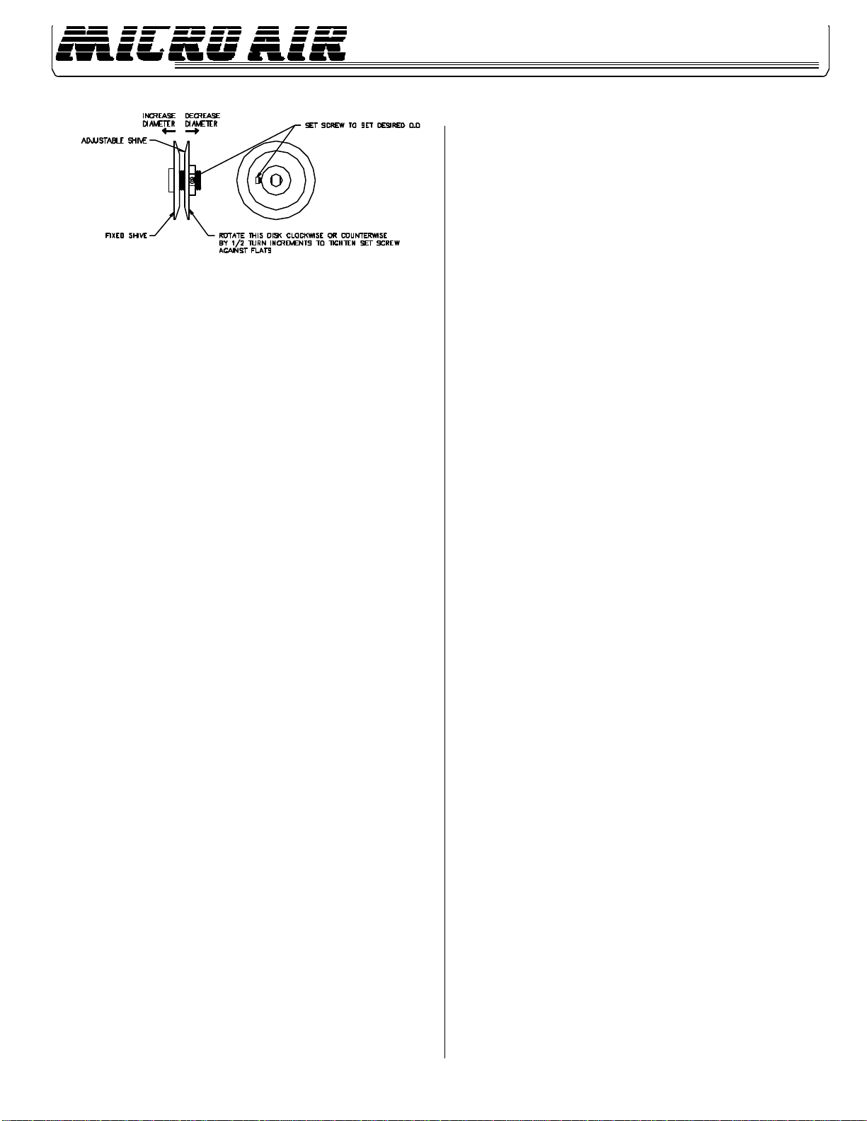
AIR FLOW ADJUSTMENT
The OM 500 is equipped with variable diameter pulleys on the motor and blower to
allowtheairflow to be adjustedtotheinstallationrequirements. Thepulleys are set for
maximumairflowatthe factory. The air flow rate can be reduced as follows:
1. Removemotorcompartmentaccess cover. Be careful to avoid tearing gasket
material between the door and the cabinet.
2. Removebeltfrommotorpulley.
3. Loosenmotorpulleyadjustment set screw andscrewadjustableshiveout away
fromfixedshive. Each turn will reduce the air flow by approximately50CFM.
Tighten set screw onto flat (see FIG.5).
3
OM500
FIG.4
4. Replacebeltandcheck for belt tension.Propertensionshouldbe approximately
1/2”deflectionwhenthebeltissqueezedtogetherwithnormalpressurebetween
fingers.
5. Iftensionistooloose, slide the motor awayfromtheblowershaftviathe slotted
holes located on the motor mount base.
6. Replacemotorcompartmentaccesscover.
7. FormultipleinletapplicationpleaserefertoMicroAir®airflowbalancingprocedure
(FormL1141).
NOTE: All filters and panels must be on the unit and door is closed for current
measurementsofmotor.
OPERATION
1. The pressure switch is preset at the factory to indicate (light on) dirty filters, but
mayneedreadjustment due to a desire for earlier or laterfilterchanges, a different
combination of filters, or because the set point shifted during shipping. The
pressureswitchisalsoorientation sensitive. Toreadjustthe switch,removethe
hole plug in the side of the unit for access to the adjustment screw. Make sure
filters and pre-filters are installed in unit. Turn the unit on and place a piece of
cardboardovertheintakecoveringabout80to85%oftheintakearea. Ona3-
inletsystem,coverentirely two inlets andalittlemorethanhalf of the areaofthe
thirdinlet. Withastandard screwdriver, turn the adjustment screw clockwise
untilthelightgoes off, or counterclockwise until the light comes on.
2. Formore time between filter changes (lessair flow), cover slightly more ofthe
opening,and for less time between filterchanges (more air flow), cover lessof
theopening.
3. Nolubrication isrequiredfor themotorbecause itisa permanentpre-lubedesign.
Excessivedirt/oilshouldbeperiodicallyremoved.
4. Makesureoilisdrainingeasilythroughdrainpipe.
FIG. 5
CHANGING FILTERS
CAUTION: Alwaysmake sure thatthe unitisturned offbeforechanging filtersor
servicing the unit.
1. The OM 500 is equipped with a filter change light, or an optional Magnehelic
Gauge, which indicates when a filter needs to be replaced. If the differential
pressurehasbeensetproperly,thelightsignalstheneed for examination of the
filters.
2. Whenthe light comes on, or thegauge reads high differential pressure, turnthe
unitoffandremovethe impinger pre-filter from the unit. Wash the pre-filter in a
detergentsolutionto remove dirt and oil residue.
3. Rinsethe pre-filter thoroughly with water, shakedry and replace it into theunit
withairflowdirection pointing to theblower.
4. Turnon the unit. If the filter change lightfails to go out, or the gauge continuesto
readhighdifferentialpressure,afterreplacingthepre-filter,thentheoilbagfilter
mayalsoneedtobe replaced.
5. Visually inspect the bag filter. If the pockets are loaded with oil and dirt, then
removethe filter from the channel and inserta new filter.
6. Starttheunit.Thefilterchangelightshouldbeoff,orthegaugereadslowdifferential
pressure,andtheunitoperating properly.
GENERAL MAINTENANCE
1. Occasionallychecktheconditionofthedrivebeltfortightnessandwear.
2. Checkthe blowerbearingsfor unusualwearand theblowerwheel fordebrisand
dirt. Clean when necessary.
3. Checkthewiringforlooseconnectionsorcrackedinsulation.
4. Nolubrication isrequiredfor themotorbecause itisa permanentpre-lubedesign.
Excessivedirt/oilshouldbeperiodicallyremoved.
5. Makesurethatoilisdrainingeasily through drain pipe.
4
OM500

TROUBLESHOOTINGCHART
CAUTION:Beforedisassemblingtheunitordoinganyinspectionoftheparts,makecertainthatthepowerhasbeencutoffand
theblowerhascometoacompletestop. Never runtheunitwiththeaccessdooropenorremoved.
PROBLEM POSSIBLE CAUSE REMEDY
Unit fails to start Deadpowerline Checkthecircuitandswitch
Blownfuse Replacefuse
Loosewireinterminalbox Reconnectwire
Burned out motor Replacemotor
Unitruns slowly or Wired for wrong voltage or Check input voltage
Inadequatecapturevelocity Improper rotation Check wiring diagram
Dirtyfilters Servicefilters
(see Changing Filters section)
Obstruction in hose/arm Reach into hood and
assembly removeobstruction
Pulleys set for static Adjust or change pulleys
Vibration Loose mounting bolts Tightenbolts
Foreign objects in blower Removeaccessdoorand
remove objects
Dirty disposable filters Servicefilters
Obstruction in hose/arm Reach into hood and
assembly removeobstruction
5
OM500
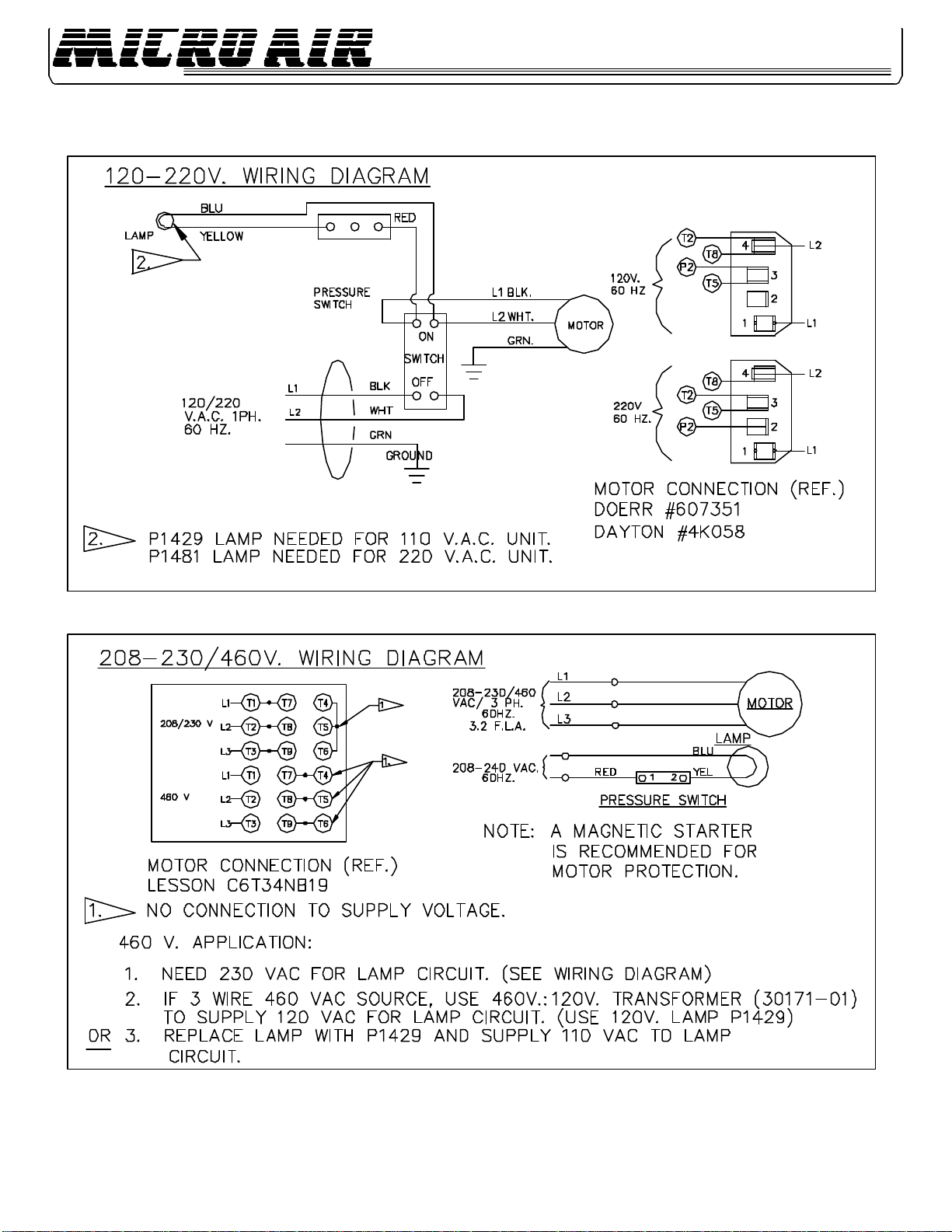
OM 500 - WIRING DIAGRAM
6
OM500
FIG.6
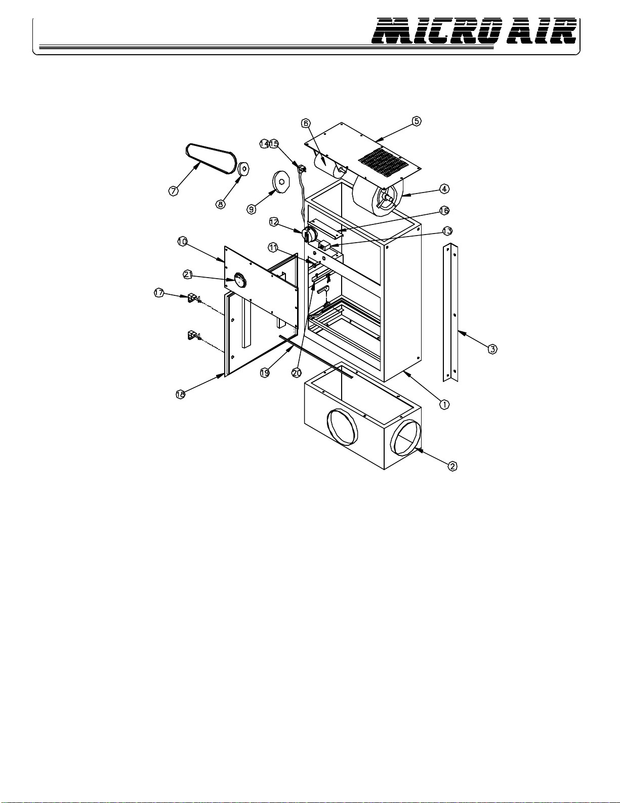
OM500-PARTSLIST
FIG. 7
ITEM PARTNO. DESCRIPTION ITEM PART NO. DESCRIPTION
1. 34126-01 Cabinet Weldment 15. P1954 Strain Relief (not shown)
2. 34142-03 Inlet Plenum (3”-8” collars) 16. 34150-01 ControlBox Cover
3. 34094-02 Wall Bracket (2 ea. required) 17. P1372 Door Latch (2 ea. required)
4. 34122-01 Blower/Rivnut Assembly (120 V & 220 V) 18. 34136-01 Filter Access Door
5. 34148-01 Exhaust Panel 19. P2126 Gasket (specify length required)
6. P1717 Motor (120 V) 20. 34161-01 Optional Hepa Kit
P1762 Motor (208-230/460 V) 21. P2250 Optional Magnehelic Gauge
7. P2064 Belt Not Shown P2061 Oil Impinger
8. P1789 Motor Pulley Not Shown P2062 Oil Bag Filter
9. P1710 Blower Pulley Not Shown P2072 Optional Hepa Filter
10. 34134-01 Front Access Panel Not Shown P2070 Optional Oil Bag Filter
11. P1429 Lamp (120 V) (used with Hepa Filter)
P1481 Lamp (220 V) Not Shown P3001 Optional 2” Max Grid Panel Filter
12. P1428 Pressure Switch Not Shown P3008 Optional 4”Mist-Xfilter (Chevron)
13. P1356 ON/OFF Switch Not Shown 34088-02 Optional Ceiling Bracket (2 ea. required)
14. P1363 Power Cord Not Shown 34162-01 Optional Base Assembly
Not Shown 34145-01 Optional 6” Diameter Collar Adapter
7
OM500

NOTES:
AIRCLEANERS
Products of Metal-Fab Inc.
P.O.BOX1138,WICHITA,KS67201
©1998 Metal-Fab, Inc. Form No. L1142 11/02
7051
Lithoin U.S.A.
8
OM500
®
Table of contents
Other MICRO-AIR Air Cleaner manuals

MICRO-AIR
MICRO-AIR MX3510 User manual

MICRO-AIR
MICRO-AIR SC150 User manual

MICRO-AIR
MICRO-AIR CLEAN AIR BOOTH User manual

MICRO-AIR
MICRO-AIR MT800 User manual

MICRO-AIR
MICRO-AIR MAE2200 User manual

MICRO-AIR
MICRO-AIR XA34 Max User manual

MICRO-AIR
MICRO-AIR SC 150 User manual

MICRO-AIR
MICRO-AIR WC2500 User manual

MICRO-AIR
MICRO-AIR WM 500 User manual

MICRO-AIR
MICRO-AIR M2150 User manual


