MicroAire 5000 Series User manual

Series-5000 Electric Instruments
Instructions for Use

IM-5000E-USA Rev A, 2021-01
TABLE OF CONTENTS
• Symbol Glossary
• Warnings and Cautions
• System Components
• Assembly / Disassembly Instructions
• Reprocessing Instructions
• Storage
• Periodic Inspection
• Repair Service
• Power Output, Noise and Vibration
• Disposal
• Warranty
. . . . . . . . . . . . . . . . . . . . . . . . . . . . . . . . . . 3-4
. . . . . . . . . . . . . . . . . . . . . . . . . . . . 5-7
. . . . . . . . . . . . . . . . . . . . . . . . . . . . . . . . 7
. . . . . . . . . . . . . 8-15
. . . . . . . . . . . . . . . . . . . . . . .15-17
. . . . . . . . . . . . . . . . . . . . . . . . . . . . . . . . . . . . . . . . . . . .18
. . . . . . . . . . . . . . . . . . . . . . . . . . . . . . . . .18
. . . . . . . . . . . . . . . . . . . . . . . . . . . . . . . . . . . . . .18
. . . . . . . . . . . . . . . . . .18
. . . . . . . . . . . . . . . . . . . . . . . . . . . . . . . . . . . . . . . . . . .18
. . . . . . . . . . . . . . . . . . . . . . . . . . . . . . . . . . . . . . . . . . .18
3 of 20 IM-5000E-USA Rev A, 2021-01
SYMBOL GLOSSARY
Symbol Name Designation
Number Use Standard Description
Refer to
Instruction
Manual /
Booklet
ISO-7010
M002
IEC 60601-
1:2005
Indicates a MANDATORY action for the
user to consult the Instructions For Use
(IFU). Symbol must be blue.
Consult
Instructions For
Use (IFU)
1641 ISO 15223-
1:2012
Indicates the need for the user to consult
the Instructions For Use (IFU).
Not required in conjunction with the
Caution symbol, if applicable.
CCaution 0434A /
0434B
ISO 15223-
1:2012
Indicates the need for the user to consult
the Instructions For Use (IFU) for
important cautionary information such as
warnings and precautions that cannot, for
a variety of reasons, be presented on the
device itself.
Non-sterile ISO 7000-2609 ISO 15223-
1:2012
To indicate that the device that is normally
provided sterile in the same or similar
packaging has not been sterilized.
Locked 5569 IEC 60878:2015 To identify on a control that a function is
locked or to show the locked status.
Unlocked 5570 IEC 60878:2015 To identify on a control that a function is
not locked or to show the unlocked status.
Lock 0018 N/A
To indicate the function of locking or
clamping two machine parts together,
or location of a machine element in a
xed position.
Unlock 0019 N/A
To indicate the function of releasing two
machine elements locked or clamped
together, or the releasing of a machine
element from a xed position.
>Temperature
Limitation 0632 ISO 15223-
1:20121
Indicates the temperature limits to which
the medical device can be safely exposed.
The upper and lower limits to temperature
shall be indicated adjacent to the upper
and lower horizontal lines.
Atmospheric
Pressure
Limitation
2621 ISO 15223-
1:20121
Indicates the range of atmospheric
pressure to which the medical device can
be safely exposed. The atmospheric
pressure limitations shall be indicated
adjacent to the upper and lower hori-
zontal lines.
Humidity
Limitation 2620 ISO 15223-
1:20121
Indicates the range of humidity to which
the medical device can be safely exposed.
The humidity limitations shall be
indicated adjacent to the upper and lower
horizontal lines.
Serial # 2498 ISO 15223-
1:2012
Indicates the manufacturer’s serial
number so that a specic medical device
can be identied.
Lot / Batch Code 2492 ISO 15223-
1:2012
Indicates the manufacturer’s batch code
so that the batch or lot can be identied.
4 of 20IM-5000E-USA Rev A, 2021-01
Symbol Name Designation
Number Use Standard Description
REF (Catalog #) 2493 ISO 15223-
1:2012
Indicates the manufacturer’s catalog
number so that the medical device can
be identied.
Do Not
Lubricate N/A N/A Indicates a medical device that is not to
be lubricated.
Do Not Immerse
in any Liquid 5995 IEC 60335-2-15 Indicates a medical device that is not to be
immersed in any liquid.
E494242
UL symbol N/A UL
MEDICAL-GENERAL MEDICAL EQUIPMENT AS
TO ELECTRIC SHOCK, FIRE, AND MECHANICAL
HAZARDS ONLY.
IN ACCORDANCE WITH ANSI/AAMI ES 60601-
1 (2005) + A1 (2012) + CAN/CSA C22.2 No.
60601-1 (2014) | Control Number: E494242
Type BF
Applied Part 5333 IEC 60601-
1:2005
Indicates a medical device complying with
the specied requirements of IEC 60601-1
to provide a higher degree of protection
against electric shock than that provided
by Type B Applied Parts.
Do Not Expose
to Stray
Magnetic Fields
N/A N/A Indicates a medical device that is not to be
exposed to stray magnetic elds.
Date of
Manufacture 2497 ISO 15223-
1:20121
Indicates the date when the medical
device was manufactured. The date is
expressed as YYYY-MM (e.g. 2015-11) or
YYYY-MM-DD (e.g. 2015-11-29).
Manufacturer 3082 ISO 15223-
1:20121Indicates the medical device manufac-
turer.
2797
CE Mark for EU
Class IIa and
Higher Products
N/A
Council
Directive
93/42/EEC
European Conformity Mark 2797 =
Notied Body Number
Prescription N/A
FDA Title 21,
Chapter 1,
Subchapter H,
Part 801.15(F)
Federal Law (U.S.A.) restricts this device to
sale by or on the order of a physician (or
properly licensed practitioner).
Dispose of per
WEEE Directive
2012/19/EU
N/A
Council
Directive
2012/19/EU
(Symbol:
European
Standard EN
50419
Indicates a medical device that is not to be
disposed of as unsorted municipal waste.
Medical device is to be disposed of per
WEEE Directive 2012/19/EU.
tUse-By Date 2607 ISO 15223-
1:2012
Indicates the date after which the medical
device is not to be used. This symbol shall
be accompanied by a date to indicate that
the medical device should not be used
after the end of the month shown.
The date is expressed as YYYY-MM
\(e.g. 2015-11) or YYYY-MM-DD
(e.g. 2015-11-29).
ISO 15223-1:2012 – “Medical devices – Symbols to be used with medical device labels, labelling and
information to be supplied – Part 1: General requirements”
ISO 7000/IEC 60417 – “Graphical symbols for use on equipment – Registered symbols”

5 of 20 IM-5000E-USA Rev A, 2021-01
WARNINGS AND CAUTIONS
The following terms are used to identify precautions that will help avoid accidental injury to patients
or personnel, or to prevent product damage:
WARNING: Indicates a risk to the safety of patients or hospital personnel.
CAUTION: Indicates a risk of damage to the system/instrument.
CAUTION: Federal Law (U.S.A.) restricts this device to sale by or on the order of a physician or
properly licensed practitioner.
CAUTION: All personnel should become familiar with this manual before using the instruments
in any procedure or during reprocessing. Personnel who are trained should include,
but are not be limited to, members of the surgical team, bioengineering department,
and central processing personnel.
WARNING: Irrigation must be used when cutting bone in order to ensure that the temperature at
the cutting accessory does not exceed 41°C / 105.8°F
WARNING: Use irrigation to prevent overheating.
WARNING: Verify that accessories are secure before use.
WARNING: Monitor the temperature of the nose section.
WARNING: Risk of pinching from moving parts.
WARNING: Risk of wrapped tissue from rotating parts.
WARNING: Risk of kick-back from high-torque devices.
WARNING: See IM-5025 for operation of the Electric Instrument Control Console.
WARNING: Ensure that there is no electromagnetic interference between the devices in this
manual and other devices in use. See IM-5025 for EMC information.
WARNING: When inserting blades, burs, rasps or twist drills, the coupler should be attached to
the handpiece, and the throttle lock should be set to LOCKED.
WARNING: Do not activate a powered instrument without first inserting the proper blade, bur,
rasp or twist drill.
WARNING: Inspect all system components for damage, corrosion, or excessive wear. Do not use if
any of these conditions are present. Contact MicroAire for service.
WARNING: If corrosion or debris are detected in or on the instrument, the instrument is
contaminated. Replace the instrument, or remove it from the sterile field to be
reprocessed.
WARNING: Do not use single-use accessories that are dull or damaged.
CAUTION: When connecting electric instrument cables, align the dots and gently push the
connections together without twisting.

6 of 20IM-5000E-USA Rev A, 2021-01
WARNING: Sterile accessory packages should be examined closely prior to opening to ensure
that there has been no loss of package integrity. Do not use sterile accessories if the
package is open or damaged because of the risk of infection.
CAUTION: To prevent damage to couplers, do not activate the instrument without first inserting
a single-use accessory.
WARNING: If the instrument runs slowly or irregularly, be alert for the possibility of overheating
or other malfunctions.
WARNING: Instrument temperature should not exceed 105°F (40°C). Monitor the instrument
temperature to prevent injury.
WARNING: Place handpiece throttle into the LOCKED position when not in use.
WARNING: The REF 5130 chuck collar must be fully in the LOCK position to prevent
overheating.
WARNING: Do not activate REF 5130 without first inserting a bur. Activation without a bur will
cause overheating.
WARNING: Do not use REF 5130 with twist drills, wires, or pins.
WARNING: Bur shaft-diameter for REF 5130 must be within the range of 2.3mm to 2.4mm. Smaller
shaft-diameters may slip, resulting in a rapid overheating; or they may eject and cause
injury.
WARNING: Do not use REF 5130 with burs whose head diameter is larger than 4.0mm. These burs
may break and cause injury.
WARNING: Select the bur-guard size for REF 5130 that properly matches the length of the bur.
WARNING: Do not use extra-long burs with the REF-5130.
CAUTION: Remove bur-guards from REF 5130 when cleaning.
WARNING: When inserting a blade into REF 5922, the hole in the blade must be seated over the
indexing pin to avoid damage or injury. Do not force the locking lever closed.
WARNING: Do not activate REF 5930 without first inserting a bur. Activation without a bur will
cause overheating.
WARNING: Do not use REF 5930 with wires or pins.
WARNING: Bur shaft-diameter for REF 5930 must be within the range of 2.3mm to 2.4mm.
Smaller shaft-diameters may slip, resulting in a rapid overheating; or they may eject,
causing injury.
WARNING: Select the bur-guard size for REF 5930 that properly matches the length of the bur:
WARNING: The chuck collar on REF 5930 must be fully in the LOCKED position to prevent
overheating.
WARNING: Make sure that the blade is centered between the two locking plates on REF 5955,
and not between just one locking plate and the edge of the instrument.
WARNING: If the blade or rasp becomes loose while the handpiece is running, the accessory is
seated improperly in REF 5945 and must be corrected.
WARNING: Protect the patient’s soft tissue near the REF 5945 chuck to prevent pinching.

7 of 20 IM-5000E-USA Rev A, 2021-01
Accessories
MicroAire 1200-Series Sagittal Saw Blades
MicroAire ZB-Series Burs
MicroAire 1400-Series and ZR-Series Reciprocating Saw Blades and Rasps
MicroAire ZS-3XX Sagittal Blades
MicroAire ZS-Series Sagittal Blades
MicroAire ZO-Series Small Oscillating Blades
MicroAire 8054-Series Standard Twist Drills
MicroAire 8053-Series Synthes-Style Twist Drills
Cleaning Brush (REF 5130-BR)
Drill Chuck Key (REF 1645-004)
Hex Driver (REF 2250-001)
Large Bur Guard (REF 5130-BG-L)
Locking Tool (REF 1745-001)
Medium Bur Guard (REF 5130-BG-M)
5130 Spare Parts Kit (5130-SP)
WARNING: Make sure that the blade is centered between the washer and the locking plate on
REF 5972, and not between just the washer and the locking nut.
WARNING: Where there is a concern about TSE/vCJD contamination, the World Health
Organization recommends processing through a pre-vacuum steam sterilization cycle
for 18 minutes at 134°C (273°F). (WHO/CDS/CSR/2000.3, “WHO Infection Control
Guidelines for TSE,”March 1999).
WARNING: After sterilization, allow instruments to cool to room temperature. Do not use
instruments that are still warm. Do not soak instruments or wrap in wet towels to cool.
SYSTEM COMPONENTS
REF Description
5000ET Electric Motor with Throttle (Handpiece)
5000E Electric Motor without Throttle (Handpiece)
5025 Electric Instrument Console
5006-5000 Instrument Cable 5000-Series to 5020/5025
5401 Series-5000 Electric Foot Pedal
5025-5401 Instrument Cable 5401 Pedal to 5020/5025
5000SC Instruments Sterilization Case 5000-Series
5922 Micro Sagittal Saw Module
5930 30K Micro Drill Module
5945 Reciprocating Saw Module
5950 Hall Style Sagittal Saw Module, Keyless
5955 Hall Style Sagittal Saw Module, with Key
5972 Oscillating Saw Module, with Key
5980 Jacobs Drill Module
5990 AO Drill (Synthes Style (Quick-Connect) Module

8 of 20IM-5000E-USA Rev A, 2021-01
ASSEMBLY / DISASSEMBLY INSTRUCTIONS
WARNING: Inspect all system components for damage, corrosion, or excessive wear. Do not use if
any of these conditions are present. Contact MicroAire for service.
WARNING: If corrosion or debris are detected in or on the instrument, the instrument is
contaminated. Replace the instrument, or remove it from the sterile field to
be reprocessed.
WARNING: Do not use single-use accessories that are dull or damaged.
1. Inspect single-use accessories (blades, burs, rasps, twist drills) for damage.
2. Place the Control Console (REF 5025/5020) on a sturdy, flat surface near a hospital-grade
outlet. Insert the power cord plug into the corresponding receptacle on the console. Insert
the plug at the other end of the power cord into a hospital-grade wall outlet. Wait for the
console to initialize, then press and hold the blinking standby button to turn on the console.
Refer to the IM-5025 console manual for more information.
3. Insert Instrument Cable (REF 5006-5000) into either of the two console ports marked with an
instrument symbol.
4. If using a Foot Pedal (REF 5401), plug the Foot Pedal Cable (REF 5025-5401) into the console
port marked with a Foot Pedal symbol. Align the marks and gently push the connectors
together. Only one Foot Pedal can be connected to the console at a time, but it can be
selected to operate either of the Foot Pedal-compatible instruments.
Align dots when connecting the cable to the handpiece. Do not twist.
Face the dot on the cable upward when connecting to the console. Do not twist.
Throttle safety lock in the LOCKEDposition and unlocked UNLOCKEDposition.
CAUTION: When connecting electric instrument cables, align the dots and gently push the
connections together without twisting.
5. Set the handpiece throttle to the LOCKEDposition. If using the Foot Pedal, ensure that it is
not accidentally activated.
6. Connect the Instrument Cable (REF 5006-5000) to the receptacle on the handpiece by
aligning the dots and gently pushing the connections together without twisting.
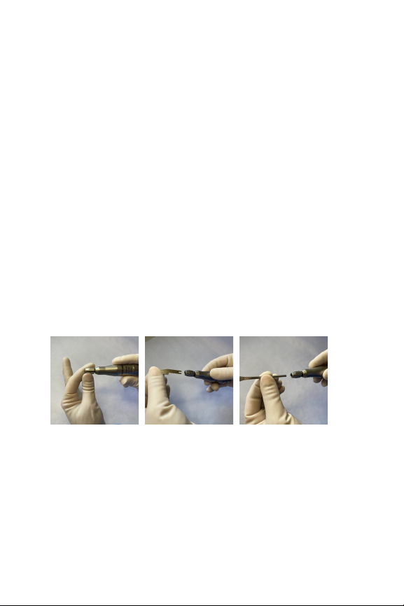
7. Connect a MicroAire Series-5000 coupler to the handpiece by retracting the collar on the
handpiece and pushing the coupler into the receptacle.

9 of 20 IM-5000E-USA Rev A, 2021-01
8. Insert a single-use accessory (blade, bur, rasp, twist drill) into the coupler.
Retract the collar on the handpiece to connect a coupler.
WARNING: Sterile accessory packages should be examined closely prior to opening to ensure
that there has been no loss of package integrity.
CAUTION: To prevent damage to couplers, do not activate the instrument without first inserting
a single-use accessory.
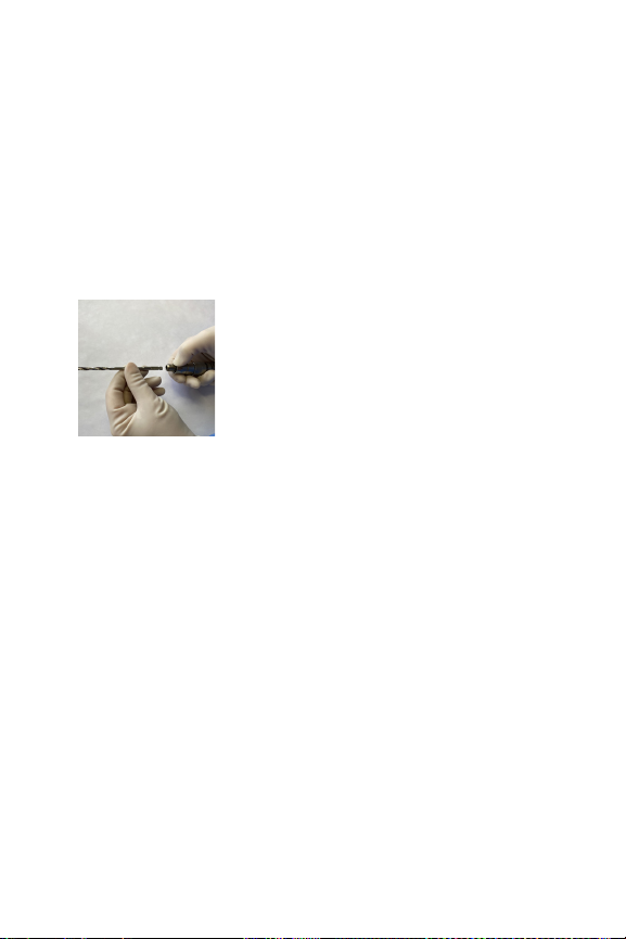
9. Test the instrument:
• Set the throttle safety lock to the to the UNLOCKEDposition.
• Press the throttle lever and test run the instrument for ve seconds.
• Conrm that the throttle does not stick in the depressed position.
• Check for irregular noise, heat, or vibration.
• Set the throttle safety lock to the LOCKEDposition.
• Contact MicroAire for service if irregularities are observed.
WARNING: If the instrument runs slowly or irregularly, be alert for the possibility of overheating
or other malfunctions.
WARNING: Instrument temperature should not exceed 105°F (40°C). Monitor the instrument
temperature to prevent injury.
WARNING: Place handpiece throttle into the LOCKEDposition when not in use.
10. Following the surgical procedure, place the handpiece throttle into the LOCKEDposition,
and disassemble the system for reprocessing.
11. Remove single-use accessories from the coupler and discard as contaminated sharps.
12. Remove the coupler from the handpiece by retracting the collar on the handpiece.
13. Remove Electric Cable (REF 5000-5006) from the console; but leave it connected to the
handpiece (REF 5000E/5000ET) to prevent the ingress of liquids into connectors during
cleaning. (The cable will be disconnected from the handpiece after cleaning, to be sterilized.)
14. Decontaminate, clean, and sterilize multi-use components according to the REPROCESSING
instructions in this manual.
REF 5130 - HIGH-SPEED DRILL MODULE
• A high-speed, low torque rotary device intended for drilling into teeth.
• Accepts MicroAire ZB-7X, ZB-1XX and ZB-2XX burs.
To insert a bur into the High-Speed Drill Module (REF 5130):
1. If using the REF 5000ET throttle-lever handpiece, set the throttle safety lock to the
LOCKEDposition.
2. If using the REF 5000E with a Foot Pedal, avoid accidentally activating the Foot Pedal while
inserting the bur.
3. Select the bur-guard size that properly matches the length of the bur:

10 of 20IM-5000E-USA Rev A, 2021-01
Bur Length Bur-Guard
47.8mm – 66.5mm Medium (REF 5130-BG-M)
69.1mm – 80mm Long (REF 5130-BG-L)
4. Twist the chuck collar to the UNLOCK position.
5. Insert a bur through the bur-guard.
6. Twist the chuck collar to the LOCK position, conrming that it is fully locked.
7. Pull on the bur to make sure it cannot be removed.
8. To use the instrument, set the throttle safety lock to the UNLOCKEDposition, or activate
the Foot Pedal.
WARNING: The REF 5130 chuck collar must be fully in the locked position to prevent
overheating.
WARNING: Do not activate REF 5130 without first inserting a bur. Activation without a bur will
cause overheating.
WARNING: Do not use REF 5130 with twist drills, wires, or pins.
WARNING: Bur shaft-diameter for REF 5130 must be within the range of 2.3mm to 2.4mm.
Smaller shaft-diameters may slip, resulting in a rapid overheating; or they may eject
and cause injury.
WARNING: Do not use REF 5130 with burs whose head diameter is larger than 4.0mm. These burs
may break and cause injury.
WARNING: Select the bur-guard size for REF 5130 that properly matches the length of the bur:
WARNING: Do not use extra-long burs with the REF 5130.
CAUTION: Remove bur-guards from REF 5130 when cleaning.
Make sure to fully lock the chuck after inserting a bur.
REF 5922 - MICRO SAGITTAL SAW MODULE
• A sagittal-motion device intended for transverse or wedge osteotomies.
• Accepts MicroAire 1200-Series blades, which are ultra-thin (0.3mm) straight, angled, bent, or
oset blades.
To insert a blade into the Micro Sagittal Saw Module (REF 5922):
1. If using the REF 5000ET throttle-lever handpiece, set the throttle safety lock to the
LOCKEDposition.
2. If using the REF 5000E with a Foot Pedal, avoid accidentally activating the Foot Pedal while
inserting the blade.
3. Press the release lever to open the blade receptacle.
4. Insert the blade into the receptacle, making sure to
t the hole in the blade over the indexing pin.
5. Release the lever.

11 of 20 IM-5000E-USA Rev A, 2021-01
6. Conrm that the blade is secure.
7. To use the instrument, set the throttle safety lock to the UNLOCKEDposition, or activate
the Foot Pedal.
WARNING: When inserting a blade into REF 5922, the hole in the blade must be seated over the
indexing pin to avoid damage or injury. Do not force the locking lever closed.
REF 5930 - 30K MICRO DRILL MODULE
• A medium speed, medium torque rotary device intended for bone sculpting, drilling, wire
passing, and reaming the intramedullary canals of small bones.
• Accepts MicroAire REF ZB-70, ZB-100, ZB-200, and ZB-300 burs.
To insert a bur into a 30K Micro Drill Module (REF 5930):
1. If using the REF 5000ET throttle-lever handpiece, set the throttle safety lock to the
LOCKEDposition.
2. If using the REF 5000E with a Foot Pedal, avoid accidentally activating the Foot Pedal while
inserting the bur.
3. Select the bur-guard size that properly matches the length of the bur:
Bur Length Bur-Guard
47.8mm – 66.5mm Medium (factory installed and cannot be removed)
69.1mm – 80mm Long (REF 1100-005)
94.5mm – 95.3mm Extra-Long (REF 1100-006)
4. Twist the chuck collar to the UNLOCKEDposition.
5. Insert a bur into the chuck.
6. Twist the chuck collar to the LOCKEDposition, conrming that it is fully locked.
7. Pull on the bur to make sure it cannot be removed.
8. To use the instrument, set the throttle safety lock to the UNLOCKEDposition, or activate
the Foot Pedal.
Make sure to fully lock the chuck after inserting a bur.
12 of 20IM-5000E-USA Rev A, 2021-01
WARNING: Do not activate REF 5930 without first inserting a bur. Activation without a bur will
cause overheating.
WARNING: Do not use REF 5930 with wires, or pins.
WARNING: Bur shaft-diameter for REF 5930 must be within the range of 2.3mm to 2.4mm.
Smaller shaft-diameters may slip, resulting in a rapid overheating; or they may eject
causing injury.
WARNING: Select the bur-guard size for REF 5930 that properly matches the length of the bur.
WARNING: The chuck collar on REF 5930 must be fully in the LOCKEDposition to prevent
overheating.
REF 5945 - RECIPROCATING SAW MODULE
• A reciprocating device intended for osteotomies using a blade; or for bone sculpting using
a rasp.
• Accepts MicroAire small-bone ZR-series reciprocating blades and rasps.
To insert a blade or rasp into the Reciprocating Saw Module (REF 5945):
1. If using the REF 5000ET throttle-lever handpiece, set the throttle safety lock to the
LOCKEDposition.
2. If using the REF 5000E with a Foot Pedal, avoid accidentally activating the Foot Pedal while
inserting the blade or bur.
3. Open the receptacle by turning the chuck counter-clockwise.
4. Insert the blade or rasp, making sure it is fully
seated in the locking collar.
5. Close and tighten the chuck by turning clockwise.
6. To use the instrument, set the throttle safety lock to the UNLOCKEDposition, or activate
the Foot Pedal.
7. Test run the instrument for 3-5 seconds. After it stops, set the throttle safety lock to the
LOCKEDposition and attempt to pull out the blade or bur to conrm it is secure.
WARNING: If the blade or rasp becomes loose while the handpiece is running, the accessory is
seated improperly in REF 5945 and must be corrected.
WARNING: Protect the patient’s soft tissue near the REF 5945 chuck to prevent pinching.
REF 5950 - HALL® STYLE SAGITTAL SAW, KEYLESS MODULE
• A sagittal-motion device intended for transverse or wedge osteotomies.
• Accepts MicroAire ZS-series blades with ve pin holes.
To insert a blade into the Hall® Style Sagittal Saw, Keyless Module (REF 5950):
1. If using the REF 5000ET throttle-lever handpiece, set the throttle safety lock to the
LOCKEDposition.

13 of 20 IM-5000E-USA Rev A, 2021-01
2. If using the REF 5000E with a Foot Pedal, avoid accidentally activating the Foot Pedal while
inserting the blade.
3. Press the small button to open the blade receptacle.
4. Insert the blade into the receptacle, making sure to t the holes in the blade over the
indexing pins.
5. Release the button.
6. Conrm that the blade is secure.
7. To use the instrument, set the throttle safety lock to the UNLOCKEDposition, or activate
the Foot Pedal.
REF 5955 - HALL® STYLE SAGITTAL SAW MODULE, WITH KEY
• A sagittal-motion device intended for transverse or wedge osteotomies.
• Accepts MicroAire ZS-series sagittal saw blades.
The blade can be locked into the saw at any angle along a180° arc.
To insert a blade into the Hall® Style Sagittal Saw Module, with Key (REF 5955):
1. If using the REF 5000ET throttle-lever handpiece, set the throttle safety lock to the
LOCKEDposition.
2. If using the REF 5000E with a Foot Pedal, avoid accidentally activating the Foot Pedal while
inserting the blade.
3. Use Hex Driver (REF 2250-001) to open the blade receptacle by turning
the locking nut counter-clockwise until a slight resistance is felt.
4. Insert the blade in the space between the two jaws making sure that the blade is fully seated.
5. Turn the hex driver clockwise to lock the blade. Do not over-tighten, but conrm that the
blade is secure.
6. To use the instrument, set the throttle safety lock to the UNLOCKEDposition, or activate
the Foot Pedal.
WARNING: Make sure that the blade is centered between the two locking plates on REF 5955,
and not between just one locking plate and the edge of the instrument.

14 of 20IM-5000E-USA Rev A, 2021-01
REF 5972 - OSCILLATING SAW MODULE, WITH KEY
• An oscillating device intended for osteotomies, especially foot procedures.
• Accepts MicroAire ZO-series small, straight, bent, and crescentic oscillating blades.
To insert a blade into the Oscillating Saw Module, with Key (REF 5972):
1. If using the REF 5000ET throttle-lever handpiece, set the throttle safety lock to the
LOCKEDposition.
2. If using the REF 5000E with a Foot Pedal, avoid accidentally activating the Foot Pedal while
inserting the blade.
3. Loosen the locking nut using Locking Tool (REF 1745-001).
4. Insert the blade in any position along an arc, between the washer and the locking plate.
5. Tighten the locking nut.
6. Conrm that the blade is secure.
7. To use the instrument, set the throttle safety lock to the UNLOCKEDposition, or activate
the Foot Pedal.
8. Test run the instrument for 3-5 seconds. After it stops, set the throttle safety lock to the
LOCKEDposition and retighten the locking nut.
WARNING: Make sure that the blade is centered between the washer and the locking plate on
REF 5972, and not between just the washer and the locking nut.
REF 5980 – JACOBS DRILL MODULE
• A low-speed, high-torque rotary device intended for drilling.
• Accepts MicroAire 8051-series and 8054-series twist drills with diameters between 1.0mm and
4.0mm, up to 127mm in length.
To insert a twist drill into the Jacobs Drill Module (5980):
1. If using the REF 5000ET throttle-lever handpiece, set the throttle safety lock to the
LOCKEDposition.
2. If using the REF 5000E with a Foot Pedal, avoid accidentally activating the Foot Pedal while
inserting the twist drill.
3. Open the chuck using Drill Chuck Key (REF 1645-004).
4. Insert the twist drill, making sure that it seats properly.
5. Close and tighten the chuck.
6. Conrm that the twist drill is secure.
7. To use the instrument, set the throttle safety lock to the UNLOCKEDposition, or activate
the Foot Pedal.
15 of 20 IM-5000E-USA Rev A, 2021-01
REF 5990 – AO DRILL (SYNTHES® STYLE QUICK CONNECT) MODULE
• A low speed, high torque rotary device intended for drilling.
• Accepts MicroAire 8053-series quick-connect twist drills with diameters between 1.1mm and
3.5mm, up to 127mm in length.
To insert a twist drill into the AO Drill (Synthes® Style) Module (REF 5990):
1. If using the REF 5000ET throttle-lever handpiece, set the throttle safety lock to the
LOCKEDposition.
2. If using the REF 5000E with a Foot Pedal, avoid accidentally activating the Foot Pedal while
inserting the twist drill.
3. Retract the chuck collar.
4. Insert the twist drill, making sure that it seats properly.
5. Release the chuck collar.
6. Conrm that the twist drill is secure.
7. To use the instrument, set the throttle safety lock to the UNLOCKEDposition, or activate
the Foot Pedal.
REPROCESSING INSTRUCTIONS
PER ISO 17664:2003 & AAMI ST 81:2004
Point of Use
Remove excess body fluids and tissue with a disposable, non-shedding wipe and cover with a cloth
dampened with purified water. Body fluids and tissue should not be allowed to dry on instruments
prior to cleaning.
NOTE: Instruments and multi-use accessories should be cleaned within 30 minutes of use to
prevent organic material from drying on the instrument.
Preparation for Decontamination
1. Remove all surgical cutting accessories (blades, burs, rasps, twist drills) from the couplers.
2. Discard single-use accessories as contaminated sharps.
3. Disassemble instruments and accessories.
4. Electric cable (REF 5000-5006) should stay connected to handpiece (REF 5000E/5000ET)
to prevent the ingress of liquids into connectors during cleaning. (The cable will be
disconnected from the handpiece after cleaning, to be sterilized.)
Cleaning – Automated
1. Load instruments into the washer disinfector.
• Avoid contact between devices which can cause damage and can obstruct washing action.
• Avoid overloading trays.
2. Arrange instruments so that cannulations are not horizontal, and openings are oriented
downward to assist drainage.

16 of 20IM-5000E-USA Rev A, 2021-01
Cycle Detergent Minutes Temp
Pre-Wash Mild pH Enzymatic* 4< = 50°C (122° F)
Rinse None 1** < = 50°C (122° F)
Wash Neutral pH 4> = 60°C (140°F)
Drain for 1 Minute Minimum
Rinse None 2** > = 60°C (140°F)
Drain for 1 Minute Minimum
Thermal Disinfect None 10 > = 93°C (200°F)
Drain for 1 Minute Minimum
* Detergent can be omitted at the pre-wash stage if the equipment does not have this function.
** If not using mild pH detergent, extend rinse time to reduce material degradation.
Cleaning - Manual
1. Do not submerge instruments in water. Cap electrical connections while cleaning to prevent
ingress of liquids.
2. Rinse handpieces, couplers, bur guards, and electric cables thoroughly with warm water
(< = 50°C / 122°F) for a minimum of 60 seconds.
3. Clean handpieces, couplers, bur guards, and electric cables using a Cavi-Wipe (or similar).
4. Clean handpieces, couplers, bur guards, and electric cables thoroughly with warm water
(< = 60°C / 140°F), mild pH enzymatic detergent, and a soft brush to scrub all surfaces for 60
seconds, paying close attention to crevices.
5. Clean central lumens of bur guards using brush REF 5130-BR (or similar), wet with detergent
but not dripping, until visibly clean.
6. Rinse handpieces, couplers, bur guards, and electric cables thoroughly under running water
(< = 50°C /122°F) for a minimum of 2 minutes. While rinsing, use brush REF 5130-BR (or similar)
in lumens and openings.
7. Repeat cleaning handpieces, couplers, bur guards, and electric cables thoroughly with warm
water (< = 60°C / 140°F), mild pH enzymatic detergent, and a soft brush to scrub all surfaces for
30 seconds, paying close attention to crevices.
8. Use a powered irrigator to ush lumens and openings. Focus the pressurized water stream into
gaps, ridges and edges.
9. Rinse handpieces, couplers, bur guards, and electric cables thoroughly under running water
(> = 50°C / 122°F) for a minimum of 2 minutes. If possible, use distilled water for the nal rinse.
10. Remove water from instruments with a soft lint-free towel or air gun.
11. Uncap electrical connections prior to sterilization.
Inspection and Function Testing
1. Disconnect Electric Cable (REF 5000-5006) from handpiece (REF 5000E/5000ET) to allow proper
sterilization of connectors.
2. Carefully inspect each device to ensure that all blood and soil has been removed.
3. Visually inspect for damage and/or wear.
4. Check the action of moving parts to ensure smooth operation throughout the intended range
of motion.
5. Confirm that couplers can be connected to the handpiece.
NOTE: If concerns are noted that may compromise the function of any MicroAire device, do
not use the device and contact MicroAire for service.

17 of 20 IM-5000E-USA Rev A, 2021-01
Sterilization
Sterilization Method Instrument Types Minimum Time &
Temperature
Minimum Heated
Dry Time
Dynamic Air Removal
(Pre-vacuum) Steam
Double-wrapped
instrument or accessory
only; or multiple
instruments and
accessories in a double-
wrapped sterilization case
3-minute full cycle
@ 135°C (275°F)
30 minutes
4-minute full cycle
@ 132°C (270°F)
30 minutes
Gravity-Displacement
Steam
Double-wrapped
instrument or accessory
only; or multiple
instruments and
accessories in a double-
wrapped sterilization case
15-minute full cycle
@ 132°C (270°F)
45 minutes
10-minute full cycle
@ 135°C (275°F)
45 minutes
WARNING: Where there is a concern about TSE/vCJD contamination, the World Health
Organization recommends processing through a pre-vacuum steam sterilization cycle
for 18 minutes at 134°C (273°F). (WHO/CDS/CSR/2000.3, “WHO Infection Control
Guidelines for TSE,”March 1999).
WARNING: After sterilization, allow instruments to cool to room temperature. Do not use
instruments that are still warm. Do not soak instruments or wrap in wet towels to cool.
ENVIRONMENTAL PARAMETERS
OPERATING CONDITIONS – This device has been tested and proven to operate within the
following conditions:
SHIPPING & STORAGE CONDITIONS
This device has been tested and proven to operate after repeated exposure to the
following conditions:
Temperature Humidity Atmospheric
50° F/10° C
86° F/30° C
>30%
75%
70 kPA
106 kPA
70 kPA
106 kPA
Temperature Humidity Atmospheric
0° F/-18° C
120° F/49° C
>10%
91%
DUTY CYCLE
Continuous operation with intermittent loading. (1-minute ON then 1-minute OFF for 6 consecutive
cycles)

18 of 20IM-5000E-USA Rev A, 2021-01
POWER OUTPUT, NOISE AND VIBRATION
DISPOSAL
To reduce the risk of contamination by biological waste, it is recommended that all devices shall
first be cleaned and sterilized. Disposal shall comply with all local, state and federal laws
and regulations.
Europe only: In accordance with the 2002/96/EC Directive on Waste Electrical and Electronic
Equipment Directive (WEEE) the product distributor is responsible for organizing a system for the
collection, storage and transfer of any and all WEEE components to Manufacturer’s approved WEEE
collection facility in Europe. Distributor shall provide on request to the manufacturer, the proof of
compliance with the European provisions regarding the WEEE Directive.
WARRANTY
MicroAire Surgical Instruments warrants Series-5000 Electric Instruments to be free from defects in
material and workmanship for a period of one year from the date of purchase. During the warranty
period, products found to have a defect in material or workmanship will be repaired or replaced
at the discretion of the manufacturer. All other expressed or implied warranties are excluded and
MicroAire shall have no liability for incidental or consequential damages. Repairs or alterations to
MicroAire products by anyone other than MicroAire, or an authorized MicroAire repair facility, will
void the product’s warranty.
STORAGE
Sterile, packaged instruments should be stored in a designated, limited-access area that is well
ventilated and provides protection from dust, moisture, insects, vermin, temperature and humidity
extremes.
PERIODIC INSPECTION
MicroAire recommends that all instruments be returned for routine inspection and service after 100
procedures. There is no charge for service during the warranty period.
REPAIR SERVICE
• Contact Customer Service for a Return Material Authorization (RMA) number.
• MicroAire may be able to solve the problem without requiring return of the item for service.
• Do not disassemble or attempt to service the equipment.
• Unauthorized repair service will void the warranty.
Unit of Measure 5000E Electric Motor
without Throttle
5000ET Electric
Motor with Throttle
Power Output kW - KiloWatts 0.05 0.05
Vibration Exposure ahv(m/s2)
Uncertainty
k (m/s2)
1.68
1.5
1.68
1.5
Noise Emission
Value
LPA (db(A))
LC, Peak (db(C))
LWA (dbA))
74 74
Mass Weight (kg) 0.22 0.25

19 of 20 IM-5000E-USA Rev A, 2021-01
NOTES

©2021 MicroAire Surgical Instruments LLC IM-5000E-USA Rev A, 2021-1
MicroAire Surgical Instruments, LLC
3590 Grand Forks Boulevard
Charlottesville, Virginia 22911 USA
In the United States:
Phone: (800) 722-0822
Fax: (800) 648-4309
Outside the United States:
Phone: (434) 975-8000
Fax: (434) 975-4131
www.microaire.com
The following company is not aliated with MicroAire Surgical
Instruments LLC.
Synthes® is a registered trademark of Depuy Synthes (USA).
This manual suits for next models
9
Table of contents
Other MicroAire Medical Equipment manuals


