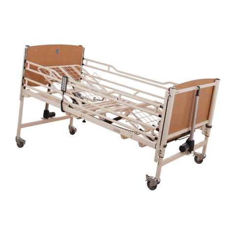
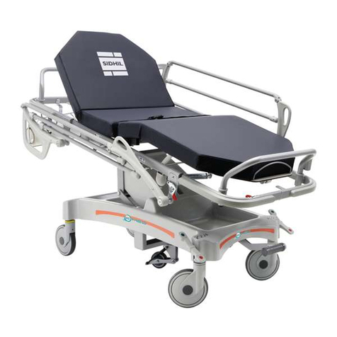
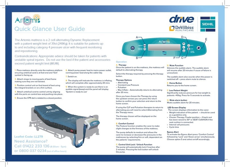
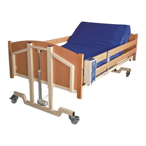
sidhil Artemis User manual

Instructions for use
Dynamic Mattress Systems
www.sidhil.com

2
Still making it better...
Welcome to Sidhil
Excellence in customer
service is our key objective.
Alongside our focus on
innovation, research and
product development, we
use our UK manufacturing
facility to ensure optimum
levels of product and
spares availability,
with unparalleled
levels of reliability and
performance.
Corporate social responsibility
is also an issue for Sidhil. We
have now received accreditation
to ISO 14001, underlining our
commitment to maintaining the
highest levels of environmental
awareness and sustainability
across our manufacturing
operation.
At Sidhil, everything we do
is designed around quality.
From our modern and ecient
manufacturing plant in Halifax,
West Yorkshire, we manufacture
a range of products for the
healthcare market using leading
edge production technology and
nishing processes.
We are the only remaining
volume manufacturer of
hospital beds in the UK,
bringing together innovation
in product development,
sales, customer service and
logistics to provide clear
benets for our customers
in terms of exibility, short
production timescales and
support from our nationwide
network of service and
maintenance centres.

3
CONTENTS
1. INTRODUCTION.................................................................................................................4
2. CONTACT INFORMATION............................................................................................4
3. PRODUCT DESCRIPTION...............................................................................................5
3.1 Environment....................................................................................................................5
3.2 Intended Use......................................................................................................................5
3.3 Features.......................................................................................................................5
4. SAFETY..........................................................................................................................6
4.1 Warnings and Cautions........................................................................................................6
4.2 RiskAssessment...................................................................................................................6
4.3 Contraindicators.....................................................................................................6
4.4 Mattress Load......................................................................................................................6
4.5 General Warnings................................................................................................................7
5. TRANSPORT AND STORAGE........................................................................................8
5.1 Storage..........................................................................................................................8
5.2 Transportation.............................................................................................................8
5.3 Environmental Conditions..................................................................................................8
6. SYMBOL DEFINITION...................................................................................................9
7. PARTS IDENTIFICATION.............................................................................................10
8. INSTALLATION....................................................................................................11
9. OPERATION.......................................................................................................15
9.1. Environmental Limits When in Operation.........................................................................15
9.2. Preparing For Use.............................................................................................................15
9.3. Control Interface..............................................................................................................15
9.4. Mattress Overview...........................................................................................................16
9.5. Control Unit Operation...................................................................................................16
9.5.1. TurningOn/Off....................................................................................................16
9.5.2. System Setup.......................................................................................................16
9.5.2.1. Alternation........................................................................16
9.5.2.2. Patient Weight and Pressure...................................................................17
9.5.3. SafetyFunctions...................................................................................................17
9.5.3.1. Function Lock........................................................................................17
9.5.3.2. Mute..........................................................................................18
9.5.4. SystemFunctions.................................................................................................18
9.5.4.1. Therapy Selection..................................................................................18
9.5.4.2. Comfort Control...................................................................................19
9.5.4.3. Additional Settings.................................................................................19
9.6. Mattress Operation..........................................................................................................22
9.6.1. AutoSeatMode....................................................................................................22
9.6.2. Low Patient Weight...........................................................................................22
9.7. CPR.....................................................................................................................22
9.8. Mattress Disconnection and Power Cuts............................................................................23
9.9. Use of Incontinence Products............................................................................................23
10. DECONTAMINATION / CLEANING..............................................................................24
10.1. Control Unit......................................................................................................................24
10.2. Mattress...................................................................................................................25
10.3. Alternative Mattress Cover Cleaning Instructions...........................................................25
11. TROUBLESHOOTING.......................................................................................26
12. MAINTENANCE..................................................................................................28
12.1. Disposal of Parts................................................................................................................29
13. SPECIFICATION..........................................................................................................30
14. ELECTROMAGNETIC COMPATIBILITY (EMC).........................................................31
14.1. Requirements According to IEC 60601-2:2007..................................................................32
15. WARRANTY....................................................................................................................36

4
Thank you for purchasing this product. These instructions for use should be read
carefully before operating the dynamic mattress and kept for future reference. Please
ensure that you understand all instructions, if you have any questions concerning the
operation or maintenance of the dynamic mattress please contact your provider.
1. INTRODUCTION
2. CONTACT INFORMATION
For any service, warranty, sales or customer service information on this product please
contact your provider or if in doubt contact Sidhil Ltd at the following address.
Please quote the control unit and/or mattress serial number on all correspondence.
Sidhil Ltd.
Sidhil Business Park
Holmfield
Halifax
West Yorkshire
HX2 9TN
UK
For Service & Support outside the UK & Northern Ireland please contact the local
distribution company from where this equipment was purchased. Failure to do so may
result in the manufacturer’s warranty becoming void.
Service & Maintenance
Tel: +44 (0)1422 233136
Fax: +44 (0)1422 233010
Spares
Tel: +44 (0)1422 233138
Fax: +44 (0)1422 233010
Customer Service
Tel: +44 (0)1422 233000
Fax: +44 (0)1422 233010
www.sidhil.com

5
Customer Service
Tel: +44 (0)1422 233000
Fax: +44 (0)1422 233010
3. PRODUCT DESCRIPTION
3.1 Environment
Your dynamic mattress system is intended for use in the following environment:
• A hospital where intensive/acute care is provided and medical supervision is
required and monitoring provided.
3.2 Intended Use
The Artemis dynamic mattress system is a high quality air support surface suitable for
individuals at very high risk, those with up to and including grade 4 pressure ulcers,
needing frequent monitoring and positioning. Via the automatic changing pressure in
the air cells the mattress provides comfort and pressure relief to patients vulnerable to
pressure damage by providing regular periods of pressure reduction to aid blood and
lymphatic flow to vulnerable tissue.
The mattress system is designed for use on both standard and profiling bed frames.
Ideally, patients allocated to this system will have some degree of independent mobility
or can be repositioned according to individual needs.
For assistance in setting up, using or maintaining your dynamic mattress system or to
report unexpected operation refer to the contact details found in section 2.
Mattress
• 23 cells: 3 static head cells and 20 alternating cells (including 8 narrow heel cells).
• Cell on cell construction.
• 10 minute cycle period.
• Securing straps.
• 2 way stretch, vapour permeable and waterproof cover.
• Automatic patient egress detection (when function is activated on control unit).
• Cable management routing.
Control Unit
• Provides air supply to mattress.
• Automatically determines patient weight (±10kg).
• Automatically sets optimum pressure for patient.
• Operated via a touch panel with integrated visual display.
• Alternating, constant low pressure, pulsation and max inflate functions.
• Customisable functions.
• Fault indicator displays.
3.3 Features

6
4. SAFETY
4.1 Warnings and Cautions
Warnings in these instructions for use highlight potential hazards that if
disregarded could lead to injury or death.
Cautions in these instructions for use highlight potential hazards that if
disregarded could lead to equipment damage or failure.
Warning
Caution
4.2 Risk Assessment
Bed frames used with the mattress system can vary greatly depending on the specific
healthcare setting (i.e. hospitals, nursing homes, home care etc). It is the responsibility
of the carer to carry out the necessary risk assessment to ensure the safety of the
patient.
Beforeapatientusesthedynamicmattresssystemariskassessmentmustbeperformed
on a patient by patient basis. The risk assessment should include, but is not limited to:
• Product combinations (bed frame, mattress, side rails etc.).
• Extent of tissue damage (if any).
• Entrapment.
• Patient falls.
• Small adults (and children).
• Patients with learning difficulties.
• Unauthorised people with access to the controls.
4.3 Contraindicators
Patientconditions forwhichthe application of pressure relief on an alternating mattress
system is a contraindication are as follows:
• Cervical or skeletal traction
• Unstable spinal fractures
Other contraindications may be relevant which are specific to the patient or care
environment.
4.4 Mattress Load
Maximum patient weight: 248kg (39 stone)

7
4.5 General Warnings
• The mattress system is to be installed and put into service in
accordance with the information provided in these instructions for
use.
• The mattress system is typically not suitable for child use, if it is
to be used for child occupancy ensure a risk assessment has been
undertaken taking into account the proportions of the child and
dimensions of the mattress system.
• Misused electrical equipment can be hazardous.
• Exposure of the control unit to any liquid while it is plugged in could
result in a severe electrical hazard.
• The control unit is a precision electronic product. Use care when
handling or transporting it. Dropping or other sudden impacts may
result in damage to the unit.
• Do not open the control unit – Risk of electrical shock.
• Repairs and service are to be conducted by suitably trained
personnel. If the control unit is not functioning properly, or has been
damaged, unplug the unit and take it out of service immediately.
• Modification of the mattress or control box is not allowed without
the permission of Sidhil Ltd – A hazard could be introduced.
• Occupants and users of this equipment must never smoke in close
proximity to the control unit, mattress or bedding being used with
it - Risk of fire.
• Accessories that have not been approved or designed for use with
the mattress system are not be used.
• Control unit shall not be used in the presence of flammable gasses
or used in oxygen rich environments – Risk of explosion / fire.
• Control unit functions must be locked out when a patient is left
unattended.
• If children, adults with learning difficulties or even pets pose a
potential risk of intentional or unintentional tampering with the
control unit its suitability for use is to be considered during the
initial patient / product risk assessment.
• The mattress is for single occupancy use. Additional weight could
damage the mattress or affect the performance of the mattress
system.
• Minimise articles (e.g. bedding) between the mattress surface and
patient, and secure bed sheets loosely so as not to affect mattress
functionality.
• Perform regular patient skin checks – Any tissue deterioration may
require equipment reallocation and/or a re-assessment of the care
being provided.
Warning

8
5. TRANSPORT AND STORAGE
5.1 Storage
• Detach the control unit from the mattress.
• Rotate the CPR dial until it is open.
• Lay the mattress out flat and position upside down.
• Ensure there is no air trapped in the cells – Note, air will only escape from the
CPR outlet and not the mattress connector.
• Position the control unit on the mattress.
• Roll from the head end towards the foot end (ensuring the control unit is fully
covered).
• Place into storage bag to protect from dirt, debris, fluids etc.
The mattress system is to be decontaminated prior to any storage to
avoid risk of cross contamination.
• Do not fold, crease or stack mattresses and/or control units -
damage could be incurred.
• Do not store whilst inflated - damage could be incurred.
Warning
Caution
• Do not remove mattress from bed frame if occupant is still on
mattress – Risk of falling.
• If essential that patient is moved whilst staying on mattress the
mattress must be re-plugged in immediately once desired location
has been reached - Risk of tissue damage due to loss of cell
alternation.
• Do not transport/move whilst inflated (unless safely secured to
bed frame) – Damage could be incurred.
• Never drag the mattress - always carry it.
Warning
Caution
5.2 Transportation
The following conditions should be followed when transporting and storing the
dynamic mattress system:
• Ambient temperature: -25°C to +70°C
• Humidity: < 93%, non-condensing
5.3 Environmental Conditions

9
6. SYMBOL DEFINITION
The following symbols are found on this bed:
(See section 9.3 for interface symbols)
Warning
Beware of potential hazard
W.E.E.E Label
(Waste Electrical and Electronic Equipment)
Refer to section 12.1
Refer to instructions for use - Mandatory
Failure to read the instructions for use could introduce a hazard
No smoking near to mattress system or whilst occupying mattress - Risk of fire
Type BF Applied Part
AppliedPart:Thepartsofthedevicethatcomeintophysicalcontactwiththeuser/occupant
in order for it to carry out its intended function (refer to secion 13 for a description of the
applied parts).
Type BF: Applied parts which are electrically isolated from earth and other parts of the
medical equipment - Complying with specific requirements for protection against electric
shock to IEC 60601-1
Mattress
The following symbols are found on the mattress:
Machine wash at 71ºC
Do not iron
Do not bleach
Do not dry clean
Tumble dry on low heat
71˚C

10
7. PARTS IDENTIFICATION
3
1
No. Item Description Qty.
1Air Cell 23
2Top Cover 1
3Air Connector 1
4Mattress Strap 8
5Base Cover 1
6CPR dial 1
No. Item Description Qty.
AControl Interface 1
BHook 2
CMains Cable Port 1
DPad 2
EAir Connector (attached to mattress) 1
FAir Filter Cover 1
2
4
5
B
C
A
D
FE
6

11
8. INSTALLATION
Refer to the warnings at the end of this section before proceeding with
installation.
• Ensure the mains supply is compatible with the control unit (see
section 13 for electrical specification)
• Avoid placing the mattress system in direct sunlight – Direct
sunlight could damage the mattress cover.
Warning
Caution
When specifying a mattress, bedframe and side rail combination a clinical assessment
of the patient’s needs must be carried out in line with local policy.
• Open all packaging with care.
• Once removed from the packaging check product for any signs of damage. If
damaged do not put into use and contact your provider or Sidhil Ltd. (see section
2).
• Remove all covers, sheets and the existing mattress from the bed.
• Position the mattress on top of the bed frame, top cover facing upwards and air
hose at the foot of the bed for control unit positioning.
• Attach to the bed frame by securing the adjustable straps to the moving sections
of the bed.
• For profiling beds, it is essential that straps are secured around the
movable sections of the bedframe – Damage will be incurred when
profiled if secured to fixed parts of frame.
• To avoid any risk of damage to the mattress ensure there are no
sharp objects which may come in contact with it.
Caution

12
• Ensure the CPR dial is rotated to a vertical or horizontal, and closed, position.
• Position the control unit by hanging the hooks over the foot board. If there is no
foot board place the unit on the floor with the front facing upwards. Ensure the
rear of the unit is not obstructed by carpet, rugs etc. It is advisable to place the
unit on a firm surface.
• Attach the air connector to the control unit, ensuring the air hose does not kink
or become trapped between parts of the bedframe.
• Route the mains cable down the length of the mattress using the integral routing
sheath. Detach the pop studs from the sheath, insert the cable and reattach all
the studs down the full length of the sheath.
• Plug the mains cable into a suitable mains supply and switch on the control unit
(see section 9).
• The mattress system will start to inflate. Inflation will be complete within 20
minutes.
CPR Closed:CPR Open:

13
• Once inflated, ensure the straps that attach the mattress to the bed frame are
secure and hold the mattress in place, adjust as necessary.
• Once the mattress is fully inflated, the bedding can be replaced. Secure sheets
loosely enough to ensure they do not interfere with cell alternation.
• Proceed to section 9 for Operation.
• Ensure the mattress is used with a compatible side rail and bed frame
combination – Incorrect combinations can lead to entrapment and/or falls
hazards.
• Ensure the mattress is of the correct type for the patient – Incorrect
mattress specification could lead to an injury.
• The mains plug is the disconnect device for the means of isolating the
control unit from the mains supply, the plug must be accessible at all times.
• Ensure the mains cable is plugged into an appropriate power source at all
times.
• To avoid the risk of electric shock, this equipment must only be connected
to a supply mains with a protective earth.
• Ensure the mains cable is not in tension, paying particular attention to
when the bed travels up/down.
• Precautions are to be taken when routing the mains cable around the bed
to ensure that it does not become squeezed, trapped or damaged by the
bedframe or other ancillary equipment - Risk of electrocution.
• Any electrical cable that is part of the mattress system or associated
ancillary equipment that is found to be damaged must be replaced
immediately - Damaged electrical cables can create a risk of electrocution
and / or fire.
• A CE marked extension cable must only be used when it is not possible to
reach a wall socket with the equipment mains cable – Contact Sidhil Ltd
for detail in regards to safe use of extension cables.
• If an extension cable is used never overload it by plugging in appliances
that together will exceed the maximum current rating stated for the
extension cable – Risk of fire.
• Block adaptors are not to be used.
• Ensure multiple socket outlets are not positioned under the bed frame -
Liquids that leak onto such a socket could pose an electrical / fire risk.
Warning

14
• Consideration is to be taken in the positioning of the mains cable and
air hose to minimise the risk of accidental strangulation resulting from
patient, baby or child entanglement – Sidhil recommend the use of the
mains cable routing sheath that is incorporated down the length of the
mattress.
• Keep away from sources of heat and naked flames (e.g. cigarettes,
fireplaces, electric fires, fan heaters, electric blankets etc.) – Close
proximity could damage the electrical system and / or mattress cover,
bedding could catch fire etc.
• Do not place any objects or items, such as blankets, on or over the control
unit - Risk of fire.
• Avoid placing the mattress system in direct sunlight – Direct sunlight could
damage the electrical system and / or mattress covers.
• Avoid placing the mattress system in a moisture rich environment -
Prolonged exposure to moisture could damage the electrical system and
pose an electrical/fire risk.
Warning

15
9. OPERATION
The following conditions should be followed when operating the dynamic mattress
system:
• Ambient temperature: +5°C to +40°C.
• Humidity: 15-93%, non-condensing.
• Atmospheric pressure: 700 hPa to 1060 hPa
9.1. Environmental Limits When in Operation
Prior to patient usage of the dynamic mattress system the following must be
performed:
• Ensure the bed and mattress system are at room temperature.
• Ensure the bed and mattress system have been cleaned and disinfected (see
section 10).
• ‘Ensure the mattress cover has been checked for tears, punctures, abrasion
marks etc. and that their are no signs of fluid ingress.’
9.2. Preparing For Use
9.3. Control Interface
No. Symbol Description
1Turns system on and off (see 9.5.1).
2
Opens therapy menu –
Provides 4 different therapy
settings (see 9.5.4.1).
3
Opens comfort control menu
– Provides 3 different comfort
settings (see 9.5.4.2).
4Selects and initiates the chosen
parameter.
1 32 4 65
89
7
No. Symbol Description
5Moves the cursor up / down the
selected menu.
6Mutes the audible signal for a 30
minute period (see 9.5.3.2).
7Returns to main screen.
8Locks / unlocks interface
functions (see 9.5.3.1).
9 - Illuminates if power is lost

16
The zoned mattress offers 3 static head cells, 12 torso cells and 8 heel cells.
The cells can be inflated between a range of 13mmHg and 70mmHg, dependent on the
function chosen.
The heel section has narrower and lower cells. The lower cells offload pressure to
protrusions such as the heels and the narrower cells offer a more supportive surface
and ensure localised pressure relief for vulnerable areas.
9.4. Mattress Overview
Hold the button down until an audible signal sounds for a brief period. The screen
illuminates.
9.5.1. Turning On / Off
9.5. Control Unit Operation
The system will be ready for use after an initial inflation period of 20minutes. Once the
mattress is fully inflated the panel will instruct the user that the system is ready for use
and a short audible signal will sound.
If the system does not reach the required pressure it will sound a ‘low pressure’
indication after 20 minutes (see section 11).
To turn the system off hold the button down until the screen extinguishes.
Once a patient is positioned on the mattress the system will determine the patient’s
approximate weight and optimum pressure level within a period of 4 minutes. Once
weight detection is complete the mattress automatically defaults to alternation mode.
9.5.2. System Setup
The mattress utilises an ‘AB’ alternation cycle where alternate cells deflate and inflate.
As the system is detecting the patient weight the screen shows the changing pressure
differential between the A and B cells at that moment in time. In the illustration below A
= 34mmHg and B = 33mmHg
9.5.2.1. Alternation
Welcome to Sidhil Artemis
Automatic Support Surface
Initializing....
Please wait until ready
Weight(kg): 40□□□□□□□□□□□□□□□□□□□□□250
Mode: System is ready to use (12,12)
Cycle Time: 10 minutes
Weight(kg): 40□□□□□□□□□□□□□□□□□□□□□250
Mode: Patient weight detection (34,33)
Cycle Time: 10 minutes

17
When the system is determining the patient weight the control unit is also calculating
the optimum pressure level for that weight of patient. The process occurs every
60 minutes or when the control unit detects a significant change in weight. The
detection works by increasing the pressure in all cells to maximum and then
decreasing them to the lowest possible supportive pressure where the patient
weight is at its heaviest (i.e. sacral, legs etc.).
The weight guidance indicator is accurate to ±10kg. In the illustration below the
weight is approximated to be 100kg with an alternating pressure of 13mmHg.
9.5.2.2. Patient Weight and Pressure
Weight(kg): 40■■■■■■□□□□□□□□□□□□□□250
Mode: Alternating (13,11)
Pressure Setting: 13 mmHg
Cycle Time: 10 minutes
The weight indicator is not to be used for medical purposes, it is to
act as information only. If the inclusion of the weight indicator could
introduce a hazard it can be hidden, see 9.5.4.3.
Warning
Once the system has set itself for the patient, re-check it after approximately 20-
30 minutes to ensure the patient is comfortable and that the system is functioning
correctly.
The control unit will automatically lockout all functionality 2 minutes after a function
change. To unlock the control unit the ‘lock’ button is pressed for 2 seconds. To re-
engage the lock the button can either be again pressed for 2 seconds or the user can
wait for the automatic lock to re-engage.
When pressed the lock indicator illuminates:
9.5.3. Safety Functions
9.5.3.1. Function Lock
Weight(kg): 40■■■■■■□□□□□□□□□□□□□□250
Mode: Alternating (13,11)
Pressure Setting: 13 mmHg
Cycle Time: 10 minutes <LOCK>

18
The audio visual signal activates if a fault is detected. To silence the audible signal the
‘mute’ button is pressed. When the system is muted the screen shows:
9.5.3.2. Mute
****MATTRESS DISCONNECT**** MUTE
Please make sure the connector is
securely fastened. (note, fault shown is an example only)
Re-pressing the mute button reactivates the audible signal.
The mute setting will self-cancel after 30 minutes and the audible signal will re-sound.
Note: If the ‘power failure’ indicator activates the mute button will not silence
the audible signal. To silence, the system must be turned off by pressing the power
button.
When silencing the ‘power failure’ indicator the audible signal will not
reactivate after 30 minutes and all lights will extinguish – There will
be no indication that the system is powered down. Ensure power is
returned to the system as soon as possible to resume pressure relief.
Warning
When pressed a menu appears offering 4 different settings:
9.5.4. System Functions
9.5.4.1. Therapy Selection
1: Alternating
2: Constant Low Pressure
3: Pulsation
4: Max Inflate
Use the up/down cursor key followed by the selection key to initiate the chosen
setting.
1) Alternating: Operates an ‘AB’ cycle where alternate cells deflate and inflate over a
defined time period (see section 9.5.4.3) causing the pressure over any one part of
the body to change regularly, actively encouraging tissue perfusion.
2) Constant low pressure: Reduces the contact pressure by increasing the surface
area over which the patient is supported and by contouring to the shape of the
body, therefore redistributing pressure away from vulnerable areas. In this setting
the system runs in a static mode where the cells are not alternating and are within a
pressure range of 10 to 40mmHg (patient weight dependent).
When using the constant low pressure setting, to return to alternating it is necessary
to manually reselect alternating from the therapy menu, it will not automatically
default back.

19
3) Pulsation: Creates tissue stimulus by alternately increasing and decreasing the cell
pressure of the constant low pressure mode by 20% in each direction.
When using the pulsation setting, to return to alternating it is necessary to manually
reselect alternating from the therapy menu, it will not automatically default back.
4) Max inflate: Inflates the cells to maximum pressure (40mmHg) to provide a stable,
static support surface.
The system will automatically revert back to alternation mode after 20 minutes for
patient safety.
When pressed a menu appears offering 3 different settings:
9.5.4.2. Comfort Control
Use the up/down cursor key followed by the selection key to initiate the chosen
setting.
By selecting this function the softness / firmness of the mattress can be manually
altered, dependent on the patient’s requirements. The pump defaults to medium.
Firm = + 5mmHg
Medium = Automated pressure setting
Soft = – 5mmHg
Before changing the pressure a clinical judgement is required from frequent
monitoring and repositioning of the patient.
1: Soft/Firm Control a: Firm
b: Medium
c: Soft
1: Cycle Time
2: Auto Lock
3: Weight Unit (kg or lbs)
Page 1/2
On accessing the comfort control menu ( ) and then pressing the lock ( ) and
down arrow ( ) buttons together a hidden menu is accessed:
9.5.4.3. Additional Settings
4: Weight Display On/Off
5: Egress Alert On/Off
6: Back to the Main Screen
Page 2/3

20
2) Auto lock: When pressed a menu appears offering 2 different settings:
By selecting ‘disable’ the interface will not automatically lock itself (see section
9.5.3.1).
Use the up/down cursor key followed by the selection key to initiate the chosen
setting.
The lock is only to be disabled in an environment where intentional/
unintentional tampering cannot occur – Sidhil recommend that the lock
is always set to ‘enable’ regardless of the environment.
Warning
Use the up/down cursor key followed by the selection key to initiate the chosen unit
of measure.
2: Auto Lock a: Enable
b: Disable
3) Weight unit: When pressed a menu appears offering 2 different settings:
3: Weight Unit a: kg
b: lbs
4) Weight display: When pressed a menu appears offering 2 different settings:
4: Weight display a: on
b: off
Use the up/down cursor key followed by the selection key to show/hide the weight
indicator on the main screen.
By selecting this function the cycle time of the alternation sequence can be manually
altered, dependent on the patient’s requirements. Note, the default cycle time for
the system when first turned on is 10 minutes.
Use the up/down cursor key followed by the selection key to initiate the chosen
setting.
1) Cycle time: When pressed a menu appears offering 3 different settings:
1: Cycle Time a: 10 mins
b: 15 mins
c: 20 mins
Other manuals for Artemis
1
Table of contents
Other sidhil Medical Equipment manuals

sidhil
sidhil E-Med 1200 User manual

sidhil
sidhil BARIATRIC DYNAMIC User manual

sidhil
sidhil Inspiration Cot User manual

sidhil
sidhil Freedom II User manual

sidhil
sidhil SOLITE-PRO User manual

sidhil
sidhil Lullaby User manual

sidhil
sidhil 1531 User manual

sidhil
sidhil 1310 User manual

sidhil
sidhil Artemis Instruction manual

sidhil
sidhil E-Med 1500 User manual