Trix BR 45 User manual

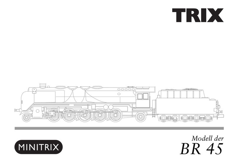
Modell der Dampflok BR 45
22945
D GB F
USA NL

2

3
Inhaltsverzeichnis: Seite
Informationen zum Vorbild 4
Hinweise zur Inbetriebnahme 6
Sicherheitshinweise 7
Wichtige Hinweise 7
Multiprotokollbetrieb 7
Hinweise zum Digitalbetrieb 8
Schaltbare Funktionen 10
Parameter/Register 11
Ergänzendes Zubehör 27
Wartung und Instandhaltung 30
Ersatzteile 36
Table of Contents: Page
Information about the prototype 4
Notes about using this model for the first time 6
Safety Notes 12
Important Notes 12
Multi-Protocol Operation 12
Notes on digital operation 13
Controllable Functions 15
Parameter/Register 16
Completing accessories 27
Service and maintenance 30
Spare Parts 36
Sommaire : Page
Informations concernant la locomotive réelle 5
Indications relatives à la mise en service 6
Remarques importantes sur la sécurité 17
Information importante 17
Mode multiprotocole 17
Remarques relatives au fonctionnement
en mode digital 18
Fonctions commutables 20
Paramètre/Registre 21
Accessoires complémentaires 27
Entretien et maintien 30
Pièces de rechange 36
Inhoudsopgave: Pagina
Informatie van het voorbeeld 5
Opmerking voor de ingebruikname 6
Veiligheidsvoorschriften 22
Belangrijke aanwijzing 22
Multiprotocolbedrijf 22
Aanwijzingen voor digitale besturing 23
Schakelbare functies 25
Parameter/Register 26
Aanvullende toebehoren 27
Onderhoud en handhaving 30
Onderdelen 36

4
Informationen zum Vorbild
Steigende Lasten und Beschleunigung des Zugverkehrs
erforderten Anfang der 1930er- Jahre die Entwicklung einer
schweren Güterzugmaschine. Als BR 45 lieferte Henschel
1937 die ersten beiden Baumusterloks ab, deren geforderte
Höchstgeschwindigkeit von 90 km/h mit 1600 mm hohen
Kuppelrädern (bei der BR 44 1.400 mm) erfüllt wurde. Die
Achsfolge war 1`E1`, zudem konnte der Kesseldruck auf
20 bar gesteigert werden und damit die Leistung auf 3.020
PSi. Die Lieferung der Serie (45 003 - 45 026) verzögerte sich
aber dann bis 1940/41.
Sie bewährten sich im schnellen und schweren Güter-
zugdienst und fuhren außerordentlich ruhig.
Nach dem Zweiten Weltkrieg wurden an den Lokomotiven
zunächst Hauptuntersuchungen durchgeführt, viele von
ihnen erhielten neue Kessel mit mechanischer Rostbeschi-
ckung. Davon verschont blieb das vorliegende Modell der 45
004, die dem Versuchsamt Göttingen als Bremslok seit 1948
zur Verfügung stand. Mitte der 1950er-Jahre kam sie zum
Versuchsamt Minden. Dort wurde sie nach einem Schaden
am Mittelzylinder noch einmal repariert und bald danach
ausgemustert.
Information about the Prototype
Increasing loads and acceleration of train service required
the development of a heavy freight locomotive at the start
of the Thirties. When Henschel delivered the first of two
sample locomotives in 1937 as the class 45, the maximum
speed of 90 km/h / 56 mph required of them was fulfilled with
1,600 mm / 63“ driving wheels (on the class 44 1,400 mm /
55-1/8“). The wheel arrangement was 2-10-2, and the boiler
pressure was increased to 290 pounds per square inch and
the power was thereby increased to 3,020 hp. Delivery of
the regular production units (road nos. 45 003 - 45 026 ) was
delayed until 1940/41.
They turned out very well in fast, heavy freight service and
ran extremely quietly.
After World War II, the locomotives first went through main
overhauls, and many of them were equipped with new boi-
lers with mechanical stokers. Of them only road no. 45 004
was preserved – the model before you – which was made
available to the Experimental Institute at Göttingen as a bra-
ke locomotive starting in 1948. It came to the Experimental
Institute in Minden in the middle of the Fifties. There it was
repaired one more time after damages to the center cylinder
and was soon retired thereafter.

5
Informations concernant la locomotive réelle
Au début des années 30, les charges de plus en plus lourdes
et l’accélération du trafic ferroviaire nécessitèrent la
conception d’une machine lourde pour la traction de trains
marchandises. En 1937 Henschel livra pour la série 45
les deux premiers prototypes qui atteignirent la vitesse
maximale exigée de 90 km/h grâce à des roues couplées de
1600 mm de diamètre (1400 mm pour la BR 44). La disposition
d’essieux était 151 ; en outre, la pression de la chaudière
pouvait être poussée à 20 bars et la puissance être ainsi
augmentée jusqu’à 3020 PSi. La livraison de la série (45 003
– 45 026) fut toutefois retardée jusqu’en 1940/41.
Les machines firent leurs preuves dans le service marchan-
dises lourd et rapide et se distinguèrent par une marche
particulièrement équilibrée.
Après la seconde guerre mondiale, les locomotives firent
d‘abord l‘objet de révisions générales et bon nombre d‘entre
elles furent dotées d‘une nouvelle chaudière avec alimenta-
tion mécanique. La locomotive 45 004 – le présent modèle -,
à la disposition du «Versuchsamt» (Office de Recherches et
d’Essais) Göttingen depuis 1948 en tant que locomotive-frein
fut épargnée. Au milieu des années 50, elle fut confiée au
bureau d`experimental Minden. Elle y fut réparée encore
une fois suite à un dommage sur le cylindre central et
réformée peu de temps après.
Informatie van het voorbeeld
Het stijgende treingewicht en het aantrekken van het
treinverkeer in het begin van de dertiger jaren, vereisten het
ontwikkelen van een zware goederentreinlocomotief. De
eerste beide prototypes leverde Henschel in 1937 als BR 45
af, welke de vereiste maximumsnelheid van 90 km/h door de
1600 mm hoge gekoppelde drijfwielen (bij de BR 44 1400 mm)
bereikten. De asindeling was 1‘E1‘ en daarnaast kon de
keteldruk tot 20 bar opgevoerd worden en daarmee het ver-
mogen tot 3020 pk. De levering van de serie (45 003 - 45 026)
werd vertraagd tot 1940/41.
Ze bewezen zich in de snelle en zware goederendienst en
liepen uiterst rustig.
Na de tweede wereldoorlog werd aan de locomotieven
eerst groot onderhoud uitgevoerd. Veel locs kregen een
nieuwe ketel met een mechanische vuurverdeling. De loc
45 004 - het voor u liggende model - bleef daarvan ver-
schoont. Sinds 1948 deed deze loc bij het testcentrum in
Göttingen dienst als rem-loc. In het midden van de vijftiger
jaren kwam deze naar het testcentrum in Minden. Daar
werd de loc na een beschadiging aan de middelste cilinder
nog één keer gerepareerd en kort daarna buitendienstge-
steld.
6
Radius > 500 mm

7
Sicherheitshinweise
• DieLokdarfnurmiteinemdafürbestimmtenBetriebssys-
tem eingesetzt werden.
• Analogmax.15Volt=,digitalmax.22Volt~.
• DieLokdarfnurausalseinerLeistungsquelleversorgt
werden.
• BeachtenSieunbedingtdieSicherheitshinweiseinder
Bedienungsanleitung zu Ihrem Betriebssystem.
• FürdenkonventionellenBetriebderLokmussdasAn-
schlussgleis entstört werden. Dazu ist das Entstörset
611 655 zu verwenden. Für Digitalbetrieb ist das Entstör-
set nicht geeignet.
• ACHTUNG! Funktionsbedingte scharfe Kanten und Spitzen.
• SetzenSiedasModellkeinerdirektenSonneneinstrah-
lung, starken Temperaturschwankungen oder hoher
Luftfeuchtigkeit aus.
Wichtige Hinweise
• DieBedienungsanleitungunddieVerpackungsind
Bestandteile des Produktes und müssen deshalb aufbe-
wahrt sowie bei Weitergabe des Produktes mitgegeben
werden.
• FürReparaturenoderErsatzteilewendenSiesichbittean
Ihren Trix-Fachhändler.
• GewährleistungundGarantiegemäßderbeiliegenden
Garantieurkunde.
• Entsorgung:www.maerklin.com/en/imprint.html
• DervolleFunktionsumfangistnurunterTrixSystems,
DCC und unter mfx verfügbar.
• Eingebaute,fahrtrichtungsabhängigeStirnbeleuchtung.
Im Digitalbetrieb schaltbar.
• BefahrbarerMindestradius360mm.
Multiprotokollbetrieb
Analogbetrieb
Der Decoder kann auch auf analogen Anlagen oder Gleis-
abschnitten betrieben werden. Der Decoder erkennt die
analoge Gleichspannung (DC) automatisch und passt sich
der analogen Gleisspannung an. Es sind alle Funktionen,
die unter mfx oder DCC für den Analogbetrieb eingestellt
wurden aktiv (siehe Digitalbetrieb).
Digitalbetrieb
Der Decoder ist ein Multiprotokolldecoder. Der Decoder
kannunterfolgendenDigital-Protokolleneingesetztwerden:
mfx oder DCC.
Das Digital-Protokoll mit den meisten Möglichkeiten ist das
höchstwertige Digital-Protokoll. Die Reihenfolge der Digital-
ProtokolleistinderWertungfallend:
Priorität1:mfx
Priorität2:DCC
Priorität3:DC
Hinweis: Digital-Protokolle können sich gegenseitig beein-
flussen. Für einen störungsfreien Betrieb empfehlen wir,
nicht benötigte Digital-Protokolle mit CV 50 zu deaktivieren.
Deaktivieren Sie, sofern dies Ihre Zentrale unterstützt, auch
dort die nicht benötigten Digital-Protokolle.
Werden zwei oder mehrere Digital-Protokolle am Gleis
erkannt, übernimmt der Decoder automatisch das höchst-
wertige Digital-Protokoll, z.B. mfx/DCC, somit wird das

8
mfx-Digital-Protokoll vom Decoder übernommen.
Hinweis: Beachten Sie, dass nicht alle Funktionen in allen
Digital-Protokollen möglich sind. Unter mfx und DCC können
einige Einstellungen von Funktionen, welche im Analog-
Betrieb wirksam sein sollen, vorgenommen werden.
Hinweise zum Digitalbetrieb
• DiegenaueVorgehensweisezumEinstellenderdiversen
Parameter entnehmen Sie bitte der Bedienungsanleitung
Ihrer Mehrzug-Zentrale.
• DieabWerkeingestelltenWertesindfürmfxgewählt,so
dass ein bestmöglichstes Fahrverhalten gewährleistet ist.
Für andere Betriebssysteme müssen gegebenenfalls
Anpassungen getätigt werden.
• DerBetriebmitgegenpoligerGleichspannungim
Bremsabschnitt ist mit der werkseitigen Einstellung
nicht möglich. Ist diese Eigenschaft gewünscht, so muss
auf den konventionellen Gleichstrombetrieb verzichtet
werden(CV29/Bit2=0).
mfx-Protokoll
Adressierung
• KeineAdresseerforderlich,jederDecodererhälteine
einmalige und eindeutige Kennung (UID).
• DerDecodermeldetsichaneinerCentralStationoder
Mobile Station mit seiner UID automatisch an.
Programmierung
• DieEigenschaftenkönnenüberdiegrascheOberäche
der Central Station bzw. teilweise auch mit der Mobile
Station programmiert werden.
• EskönnenalleCongurationVariablen(CV)mehrfach
gelesen und programmiert werden.
• DieProgrammierungkannentwederaufdemHaupt-oder
dem Programmiergleis erfolgen.
• DieDefaulteinstellungen(Werkseinstellungen)können
wieder hergestellt werden.
• Funktionsmapping:FunktionenkönnenmitHilfeder
Central Station 60212 (eingeschränkt) und mit der Central
Station 60213/60214/60215 beliebigen Funktionstasten
zugeordnet werden (siehe Hilfe in der Central Station).
DCC-Protokoll
Adressierung
• KurzeAdresse–LangeAdresse–Traktionsadresse
• Adressbereich:
1 – 127 kurze Adresse, Traktionsadresse
1 – 10239 lange Adresse
• JedeAdresseistmanuellprogrammierbar.
• KurzeoderlangeAdressewirdüberdieCVsausgewählt.
• EineangewandteTraktionsadressedeaktiviertdie
Standard-Adresse.
Programmierung
• DieEigenschaftenkönnenüberdieCongurationsVaria-
blen (CV) mehrfach geändert werden.
• DieCV-NummerunddieCV-Wertewerdendirekteinge-
geben.
• DieCVskönnenmehrfachgelesenundprogrammiert
werden (Programmierung auf dem Programmiergleis).
• DieCVskönnenbeliebigprogrammiertwerden(Program-

9
mierung auf dem Hauptgleis PoM). PoM ist nur bei den in
der CV-Tabelle gekennzeichneten CV möglich. Die Pro-
grammierung auf dem Hauptgleis (PoM) muss von Ihrer
Zentrale unterstützt werden (siehe Bedienungsanleitung
ihres Gerätes).
• DieDefaulteinstellungen(Werkseinstellungen)können
wieder hergestellt werden.
• 14bzw.28/126Fahrstufeneinstellbar.
• AutomatischesBremsen(CV27=Wert16)
• AlleFunktionenkönnenentsprechenddemFunktions-
mapping geschaltet werden.
• WeitereInformation,sieheCV-TabelleDCC-Protokoll.
Es wird empfohlen, die Programmierungen grundsätzlich auf
dem Programmiergleis vorzunehmen.
Logische Funktionen
Anfahr-/Bremsverzögerung
• DieBeschleunigungs-undBremszeitkanngetrenntvon
einander eingestellt werden.
• DielogischeFunktionsabschaltungABVkannüberdas
Funktionsmapping auf jede beliebige Funktionstaste
gelegt werden.

10
Schaltbare Funktionen
Spitzensignal an Funktion f0 Funktion f0
Rauchgenerator — Funktion 1 Funktion f1 Funktion f1
Geräusch:Betriebsgeräusch — Funktion 2 Funktion f2 Funktion f2
Geräusch:Lokpfeifelang — Funktion 3 Funktion f3 Funktion f3
ABV aus — Funktion 4 Funktion f4 Funktion f4
Geräusch:Bremsenquietschenaus — Funktion 5 Funktion f5 Funktion f5
Geräusch:Führerstandsbeleuchtung —Funktion 6 Funktion f6 Funktion f6
Geräusch:Rangierpff — Funktion 7 Funktion f7 Funktion f7
Telex-Kupplung hinten — Funktion 8 Funktion f8 Funktion f8
Flackerlicht Feuerbüchse — — Funktion f9 Funktion f9
Geräusch:Dampfablassen — — Funktion f10 Funktion f10
Geräusch:Kohleschaufeln — — Funktion f11 Funktion f11
Geräusch:Schüttelrost — — Funktion f12 Funktion f12
Geräusch:Luftpumpe — — Funktion f13 Funktion f13
Geräusch:Injektor — — Funktion f14 Funktion f14
STOP mobile station
15
f0 f8 f0f8
f0 - f3 f4 - f7

11
CV Bedeutung Wert DCC ab Werk
1 Adresse 1 - 127 3
2 PoM Minimalgeschwindigkeit 0 - 255 18
3 PoM Anfahrverzögerung 0 - 255 15
4 PoM Bremsverzögerung 0 - 255 15
5 PoM Maximalgeschwindigkeit 0 - 255 235
8 Werkreset/Herstellerkennung 8 131
13 PoM Funktionen F1 - F8 im Analogbetrieb 0 - 255 1
14 PoM Funktionen F9 - F15 und Licht im Analogbetrieb 0 - 255 1
17 Erweiterte Adresse (oberer Teil) CV29,Bit5=1 192
18 Erweiterte Adresse (unterer Teil) CV29,Bit5=1 128
19 Traktionsadresse 0 - 255 0
21 PoM Funktionen F1 - F8 bei Traktion 0 - 255 0
22 PoM Funktionen F9 - F15 und Licht bei Traktion 0 - 255 0
29 PoM
Bit0:UmpolungFahrtrichtung
Bit1:AnzahlFahrstufen14oder28/128*
Bit2:DCCBetriebmitBremsstrecke(keinAnalogbetriebmöglich)
Bit5:Adressumfang7Bit/14Bit
0 / 1
0 / 2
0 / 4
0 / 32
***
0, 1, 2, 3, 4, 5, 6,
7, 32, 34, 35, 36,
37, 38, 39
6
63 PoM Lautstärke 0 - 255 255
PoM Program on the Main; muss vom Steuergerät unterstützt werden
* FahrstufenamLokdecoderundamSteuergerätmüssenübereinstimmen,essindsonstFehlfunktionenmöglich.
*** DieWertedergewünschtenEinstellungensindzuaddieren!

12
travel. They can be turned on and off in digital operation.
• Minimumradiusforoperationis360mm/14-3/16“.
• Asmokegeneratorcanberetrottedtothelocomotive-
also for analog operation.
Multi-Protocol Operation
Analog Operation
This decoder can also be operated on analog layouts or ar-
eas of track that are analog. The decoder recognizes alter-
nating current (DC) and automatically adapts to the analog
track voltage. All functions that were set under mfx or DCC
for analog operation are active (see Digital Operation).
Digital Operation
The decoders are multi-protocol decoders. These decoders
canbeusedunderthefollowingdigitalprotocols:mfxorDCC.
The digital protocol with the most possibilities is the highest
order digital protocol. The sequence of digital protocols in
descendingorderis:
Priority1:mfx
Priority2:DCC
Priority3:DC
Note: Digital protocols can influence each other. For trouble-
free operation, we recommend deactivating those digital
protocols not needed by using CV 50. Deactivate unneeded
digital protocols at this CV if your controller supports this
function.
If two or more digital protocols are recognized in the track,
the decoder automatically takes on the highest order digital
protocol,example:mfx/DCC;thedecodertakesonthemfx
Safety Notes
• Thislocomotiveisonlytobeusedwiththeoperating
system it is designed for.
• Analogmax.15voltsDC,digitalmax.22voltsAC.
• Thislocomotivemustneverbesuppliedwithpowerfrom
more than one power pack.
• Pleasemakenoteofthesafetynotesintheinstructions
for your operating system.
• Thefeedertrackmustbeequippedtopreventinter-
ference with radio and television reception, when the
locomotive is to be run in conventional operation. The
611 655 interference suppression set is to be used for this
purpose. The interference suppression set is not suitable
for digital operation.
• WARNING! Sharp edges and points required for operation.
• Donotexposethemodeltodirectsunlight,extreme
changes in temperature, or high humidity.
Important Notes
• Theoperatinginstructionsandthepackagingareacom-
ponent part of the product and must therefore be kept as
well as transferred along with the product to others.
• PleaseseeyourauthorizedTrixdealerforrepairsor
spare parts.
• Thewarrantycardincludedwiththisproductspecies
the warranty conditions.
• Disposing:www.maerklin.com/en/imprint.html
• ThefullrangeoffunctionsisonlyavailableunderTrix
Systems and under DCC.
• Built-inheadlightsthatchangeoverwiththedirectionof

13
digital protocol (see previous table).
Note: Please note that not all functions are possible in all
digital protocols. Several settings for functions, which are
supposed to be active in analog operation, can be done
under mfx and DCC.
Notes on digital operation
• Theoperatinginstructionsforyourcentralunitwillgive
you exact procedures for setting the different parameters.
• Thevaluessetatthefactoryhavebeenselectedformfx
in order to guarantee the best possible running characte-
ristics.
Adjustments may have to be made for other operating
systems.
• Thesettingdoneatthefactorydoesnotpermitoperation
with opposite polarity DC power in the braking block.
If you want this characteristic, you must do without
conventionalDCpoweroperation(CV29/Bit2=0).
mfx Protocol
Addresses
• Noaddressisrequired;eachdecoderisgivenaone-
time, unique identifier (UID).
• ThedecoderautomaticallyregistersitselfonaCentral
Station or a Mobile Station with its UID.
Programming
• Thecharacteristicscanbeprogrammedusingthe
graphic screen on the Central Station or also partially
with the Mobile Station.
• AlloftheCongurationVariables(CV)canbereadand
programmed repeatedly.
• Theprogrammingcanbedoneeitheronthemaintrackor
the programming track.
• Thedefaultsettings(factorysettings)canbeproduced
repeatedly.
• Functionmapping:Functionscanbeassignedtoanyof
the function buttons with the help of the 60212 Central
Station (with limitations) and with the 60213/60214/60215
Central Station (See help section in the Central Station).
DCC Protocol
Addresses
• Shortaddress–longaddress–multipleunitaddress
• Addressrange:
1 – 127 for short address and multiple unit address,
1 – 10239 for long address
• Everyaddresscanbeprogrammedmanually.
• AshortoralongaddressisselectedusingtheCVs.
• Amultipleunitaddressthatisbeinguseddeactivatesthe
standard address.
Programming
• Thecharacteristicscanbechangedrepeatedlyusingthe
Configuration Variables (CV).
• TheCVnumbersandtheCVvaluesareentereddirectly.
• TheCVscanbereadandprogrammedrepeatedly.(Pro-
gramming is done on the programming track.)
• TheCVscanbeprogrammedinanyorderdesired.(Pro-
gramming can be done on the main track PoM). The PoM

14
can only be done with those designated in the CV table.
Programming on the main track PoM must be supported
by your central controller (Please see the description for
this unit.).
• Thedefaultsettings(factorysettings)canbeproduced
repeatedly.
• 14/28or126speedlevelscanbeset.
• Allofthefunctionscanbecontrolledaccordingtothe
function mapping (see CV description).
• SeetheCVdescriptionfortheDCCprotocolforadditional
information.
We recommend that in general programming should be
done on the programming track.
Logic Functions
Acceleration/Braking Delay
• Theaccelerationandbrakingtimecanbesetseparately
from each other.
• ThelogicfunctionABVcanbeassignedtoanyfunction
button by using the function mapping.

15
Controllable Functions
Headlights on Function f0 Function f0
Smoke generator — Function 1 Function f1 Function f1
Soundeffect:Operatingsounds — Function 2 Function f2 Function f2
Soundeffect:longwhistleblast — Function 3 Function f3 Function f3
ABV off — Function 4 Function f4 Function f4
Soundeffect:Squealingbrakesoff — Function 5 Function f5 Function f5
Soundeffect:Engineer‘scablighting — Function 6 Function f6 Function f6
Soundeffect:Shortwhistleblast — Function 7 Function f7 Function f7
Rear Telex coupler — Function 8 Function f8 Function f8
Glow from firebox — — Function f9 Function f9
Soundeffect:Blowingoffsteam — — Function f10 Function f10
Soundeffect:Coalbeingshoveled — — Function f11 Function f11
Soundeffect:Rockergrate — — Function f12 Function f12
Soundeffect:Airpump — — Function f13 Function f13
Soundeffect:Injector — — Function f14 Function f14
STOP mobile station
15
f0 f8 f0f8
f0 - f3 f4 - f7

16
PoM Program on the Main; must be supported by the controller
* Thespeedlevelsonthelocomotivedecoderandonthecontrollermustagreewitheachother;otherwise,
you may have malfunctions.
*** Thevaluesforthedesiredsettingsmustbeadded.
CV Discription DCC Value Factory-Set
1 Address 1 - 127 3
2 PoM Minimum Speed 0 - 255 18
3 PoM Acceleration delay 0 - 255 15
4 PoM Braking delay 0 - 255 15
5 PoM Maximum speed 0 - 255 235
8 Factory Reset / Manufacturer Recognition 8 131
13 PoM Functions F1 - F8 in analog operation 0 - 255 1
14 PoM Functions F9 - F15 and lights in analog operation 0 - 255 1
17 Extended address (upper part) CV29,Bit5=1 192
18 Extended address (lower part) CV29,Bit5=1 128
19 Multiple Unit Address 0 - 255 0
21 PoM Functions F1 - F8 on Multiple Unit 0 - 255 0
22 PoM Functions F9 - F15 and lights on Multiple Unit 0 - 255 0
29 PoM
Bit0:Reversingdirection
Bit1:Numberofspeedlevels14or28/128*
Bit2:DCCoperationwithbrakingarea
(no analog operation possible)
Bit5:Addresslength7Bit/14Bit
0 / 1
0 / 2
0 / 4
0 / 32
***
0, 1, 2, 3, 4, 5, 6,
7, 32, 34, 35, 36,
37, 38, 39
6
63 PoM Volume 0 - 255 255

17
Remarques importantes sur la sécurité
• Lalocomotivenepeutêtreutiliséequ‘aveclesystème
d‘exploitation indiqué.
• Analogiquemax.15Volt=,digitalmax.22Volt~.
• Lalocomotivenepeutpasêtrealimentéeélectriquement
par plus d‘une source de courant à la fois.
• Ilestimpératifdetenircomptedesremarquessurla
sécurité décrites dans le mode d‘emploi de votre système
d‘exploitation.
•
Pour l’exploitation de la locomotive en mode conventi-
onnel, la voie de raccordement doit être déparasitée. A
cet effet, utiliser le set de déparasitage réf. 611 655. Le set
de déparasitage ne convient pas pour l’exploitation en
mode numérique.
•
ATTENTION! Pointes et bords coupants lors du fonctionne-
ment du produit.
• Nepasexposerlemodèleàunensoleillementdirect,
à de fortes variations de température ou à un taux
d‘humidité important.
Information importante
• Lanoticed‘utilisationetl’emballagefontpartieintégrante
du produit ; ils doivent donc être conservés et, le cas
échéant, transmis avec le produit.
• Pourtouteréparationouremplacementdepièces,
adressez vous à votre détaillant-spécialiste Trix.
• Garantielégaleetgarantiecontractuelleconformément
au certificat de garantie ci-joint.
• Elimination:www.maerklin.com/en/imprint.html
• L’intégralitédesfonctionsestdisponibleuniquementen
exploitation Trix Systems, DCC et mfx.
• Feuxdesignalisations‘inversantselonlesensdemar-
che; feux commutables en exploitation digital.
• Rayonminimald’inscriptionencourbe360mm.
• Installationultérieured’ungénérateurdefuméepossible
- également pour exploitation analogique.
Mode multiprotocole
Mode analogique
On peut aussi faire fonctionner le décodeur sur des installa-
tions ou des sections de voie analogiques. Le décodeur identi-
fie automatiquement la tension de voie analogique (CC). Toutes
les fonctions qui ont été paramétrée pour le mode analogique
sous mfx ou sous DCC sont actives (voir mode numérique).
Mode numérique
Les décodeur sont des décodeur multiprotocole. Le
décodeur peut être utilisé avec les protocoles numériques
suivants:mfx,DCC
Le protocole numérique offrant les possibilités les plus
nombreuses est le protocole numérique à bit de poids
fort. La hiérarchisation des protocoles numériques est
descendante:
Priorité1:mfx
Priorité2:DCC
Priorité3:
DC
Indication : des protocoles numériques peuvent s’influencer
réciproquement. Pour une exploitation sans perturbations,
nous recommandons de désactiver avec CV 50 des proto-
coles numériques non nécessaires.

18
Dans la mesure où votre centrale les supporte, désactivez y
aussi les protocoles numériques non nécessaires.
Lorsque deux ou plusieurs protocoles numériques sont
identifiés au niveau de la voie, le décodeur reprend automa-
tiquement le protocole numérique à bit de poids fort, p. ex.
mfx/DCC. Le protocole numérique mfx est donc repris par le
décodeur (voir tableau antérieur).
Indication : remarquez que toutes les fonctions ne peuvent
pas être actionnées dans tous les protocoles numériques.
Sous mfx et sous DCC, il est possible de procéder à
quelques paramétrages de fonctions devant être actives
dans le cadre de l’exploitation analogique.
Remarques relatives au fonctionnement en mode
digital
• Encequiconcernelaprocédurederéglagedesdivers
paramètres, veuillez vous référer au mode d‘emploi de
votre centrale de commande multitrain.
• Lesvaleursparamétréesd’usinesontchoisiespour
mfx de manière à garantir le meilleur comportement de
roulement possible.
Pour d’autres systèmes d’exploitation, ces valeurs
devront éventuellement être adaptées.
• Lesvaleursparamétréesd’usinesontchoisiesdema-
nière à garantir le meilleur comportement de roulement
possible.
• L’exploitationaveccourantcontinudepolaritéinverse
dans les sections de freinage n’est pas possible avec
le réglage d’usine. Si cette propriété est désirée, il faut
alors renoncer à l’exploitation conventionnelle en cou-
rantcontinu(CV29/Bit2=0).
Protocole mfx
Adressage
• Aucuneadressen’estnécessaire,ledécodeurreçoittou-
tefois une identification unique et non équivoque (UID).
• AvecsonUID,ledécodeurindiqueautomatiquement
à une station centrale ou à une station mobile qu’il est
connecté.
Programmation
• Lescaractéristiquespeuventêtreprogramméespar
l’intermédiaire de la couche graphique de la station cen-
trale, voire en partie aussi au moyen de la station mobile.
• Touteslescongurationsvariables(CV)peuventêtrelues
etprogramméesdefaçonréitérée.
• Laprogrammationpeutêtreréaliséesoitsurlavoie
principale, soit sur la voie de programmation.
• Lesparamétragespardéfaut(paramétragesusine)
peuvent être rétablis.
• Mappagedesfonctions:lesfonctionspeuventêtre
affectées à de quelconques touches de fonction au
moyen de la station centrale (60212) (restreinte) et avec
la station centrale 60213/60214/60215 (voir Aide au niveau
de la station centrale).
Protocole DCC
Adressage
• Adressebrève–adresselongue–adressedetraction.
• Champd’adresse:
1 – 127 adresse brève, adresse de traction
1 – 10239 adresse longue

19
• Chaqueadresseestprogrammablemanuellement.
• L’adressebrèveoulongueestchoisieparl’intermédiaire
des CVs.
• Uneadressedetractionutiliséedésactivel’adresse
standard.
Programmation
• Lescaractéristiquespeuventêtremodiéesdefaçon
réitérée par l’intermédiaire des variables de configuration
(CVs).
• Touteslescongurationsvariables(CV)peuventêtrelues
etprogramméesdefaçonréitérée.
• Laprogrammationpeutêtreréaliséesoitsurlavoie
principale, soit sur la voie de programmation.
• LesCVspeuventêtreprogramméeslibrement(pro-
grammation de la voie principale (PoM). La PoM n’est
possible que pour les CVs identifiées dans le tableau des
CVs. La programmation sur la voie principale (PoM) doit
être supportée par votre centrale (voir mode d’emploi de
votre appareil).
• Lesparamétragespardéfaut(paramétragesusine)
peuvent être rétablis.
• 14/28,voire126cransdemarchesontparamétrables.
• Touteslesfonctionspeuventêtrecommutéesenfonction
du mappage des fonctions (voir le descriptif des CVs).
• Pourtouteinformationcomplémentaire,voirletableau
des CVs, protocole DCC.
Il est recommandé, de réaliser la programmation, fonda-
mentalement, sur la voie de programmation.
Fonctions logiques
Retard au démarrage / au freinage
• Lestempsd’accélérationetdefreinagepeuventêtre
paramétrés séparément les uns des autres.
• Parl’intermédiairedumappagedesfonctions,lamise
hors fonction de la fonction logique ABV peut être affec-
tée à n’importe quelle touche de fonction.

20
Fonctions commutables
Fanal éclairage activé Fonction f0 Fonction f0
Générateurdefumée* — Fonction 1 Fonction f1 Fonction f1
Bruitage:Bruitd’exploitation — Fonction 2 Fonction f2 Fonction f2
Bruitage:Sifetlongueur — Fonction 3 Fonction f3 Fonction f3
ABV, désactivé — Fonction 4 Fonction f4 Fonction f4
Bruitage:Grincementdefreinsdésactivé — Fonction 5 Fonction f5 Fonction f5
Eclairage de la cabine de conduite — Fonction 6 Fonction f6 Fonction f6
Bruitage:Sifetpourmanœuvre — Fonction7 Fonction f7 Fonction f7
Attelage Telex — Fonction 8 Fonction f8 Fonction f8
Lueurs dans le foyer — — Fonction f9 Fonction f9
Bruitage:Échappementdelavapeur — — Fonction f10 Fonction f10
Bruitage:Pelletageducharbon — — Fonction f11 Fonction f11
Bruitage:Grilleàsecousses — — Fonction f12 Fonction f12
Bruitage:Compresseur — — Fonction f13 Fonction f13
Bruitage:Injecteur — — Fonction f14 Fonction f14
* Nefaitpaspartiedelafourniture.
STOP mobile station
15
f0 f8 f0f8
f0 - f3 f4 - f7
Other manuals for BR 45
1
This manual suits for next models
1
Table of contents
Languages:
Other Trix Toy manuals

Trix
Trix 403 User manual

Trix
Trix Minitrix BR 44 User manual

Trix
Trix Big Boy 4014 User manual

Trix
Trix BR 03 22144 User manual

Trix
Trix 103 101-2 User manual

Trix
Trix Big Boy 22062 User manual

Trix
Trix BR 152 User manual

Trix
Trix BR 10 User manual

Trix
Trix H0 5519 User manual

Trix
Trix BR 03 Altbau User manual
Popular Toy manuals by other brands

Mattel
Mattel HOTWHEELS MARIOKART GXX41-4B70 instructions

Reely
Reely NEW1 operating instructions

Beyblade
Beyblade B-12 instructions

Vollmer
Vollmer 45738 Mounting instruction

Robinson Helicopter Company
Robinson Helicopter Company R66 Pilot operating handbook

Seagull Models
Seagull Models SEA238 Assembly manual