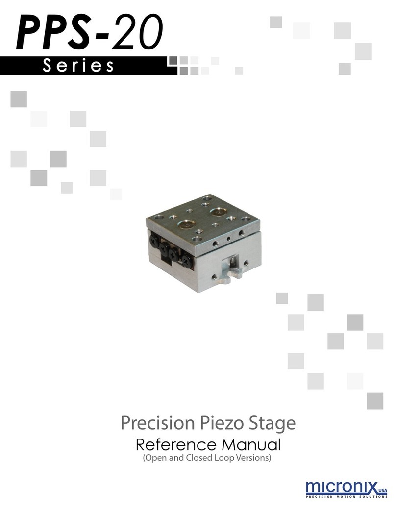
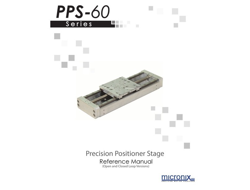
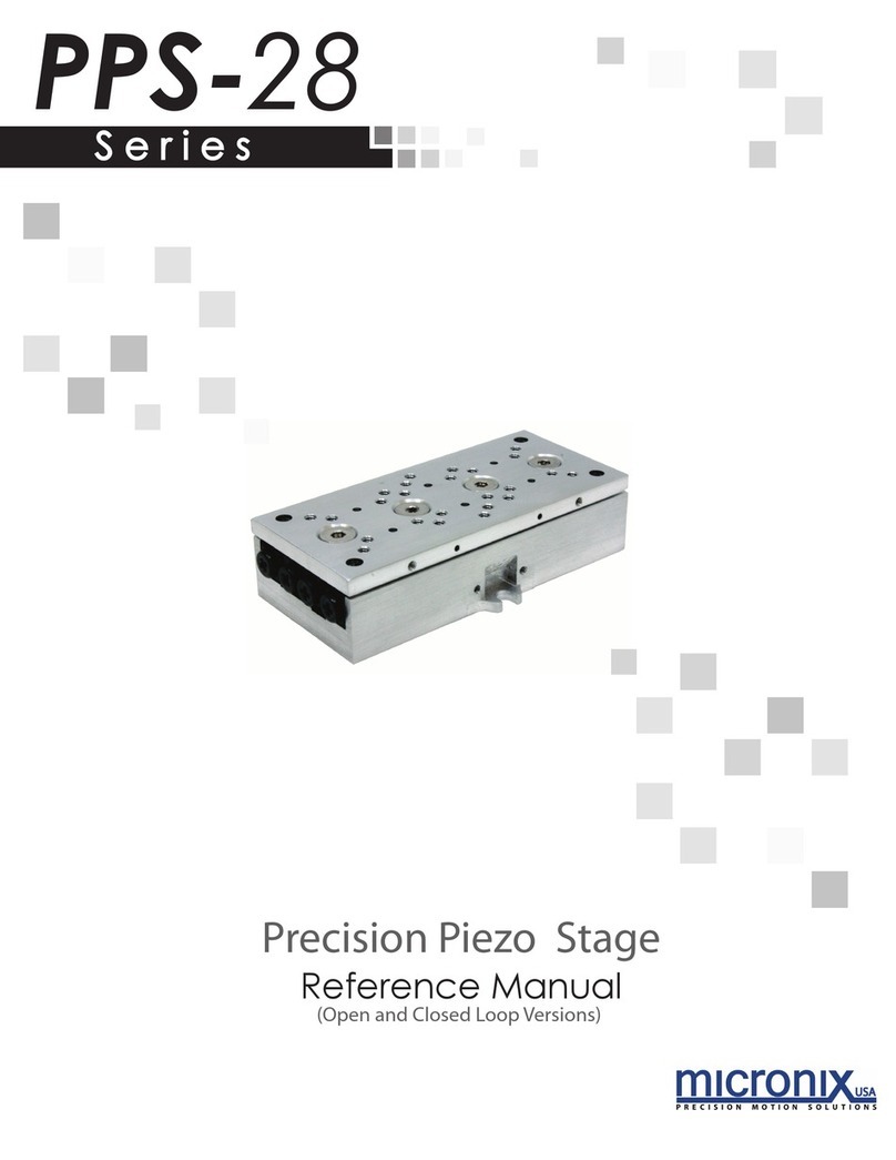
Micronix PP-18 Series User manual

S e r i e s
Reference Manual
Piezo Positioner Stage
(Open and Closed Loop Versions)
PP-18

PP-18
Piezo Positioner Stage
Reference Manual
Rev 1.3
MICRONIX USA, LLC
Tel: 949-480-0538
Fax: 949-480-0538
Email: [email protected]
http://micronixusa.com

PP-18 Piezo Positioner Stage
1
Rev: 1.3
MICRONIX USA,LLC
www.micronixusa.com
Reference Manual
Contents
1. Introduction ………….2
1.1 Product Description.................................................................................................................................................................................................................2
1.2 Recommended Controllers......................................................................................................................................................................................................3
1.3 Technical Data.........................................................................................................................................................................................................................3
1.4 Load Characteristics ................................................................................................................................................................................................................3
2. Model Configurations 4
2.1 PP-18 Order Numbers .............................................................................................................................................................................................................4
3. Preparing to Install the PP-18 ………………….5
3.1 Installation Preparation ..........................................................................................................................................................................................................5
3.2 Package Contents....................................................................................................................................................................................................................5
4. Installing the PP-18 ……6
4.1 PP-18 Installation ....................................................................................................................................................................................................................6
4.1.1 General Mounting ........................................................................................................................................................................................................6
4.1.2 X-Y Mounting................................................................................................................................................................................................................7
5. Connecting the PP-18 ….8
5.1 Atmospheric Environments.....................................................................................................................................................................................................8
6. Dimensions …9
6.1 PP-18 with Digital Encoder......................................................................................................................................................................................................9
7. Stacking Configurations .. 9
7.1 Configurations Examples.........................................................................................................................................................................................................9
8. Supplementary Information ..10
8.1 Maintenance .........................................................................................................................................................................................................................10
8.2 Units and Conventions ..........................................................................................................................................................................................................10
A. Appendix 11
A.1 Electrical Connections...........................................................................................................................................................................................................11
A.1.1 DB-9 Standard Male Motor Connector.......................................................................................................................................................................11
A.1.2 Encoder Pinout...........................................................................................................................................................................................................11
A.2 2 Phase Piezo Motor Wiring Diagram....................................................................................................................................................................................11
'A.3 Resolution.............................................................................................................................................................................................................................12

PP-18 Piezo Positioner Stage
2
Rev: 1.3
MICRONIX USA,LLC
www.micronixusa.com
Reference Manual
1. 0BIntroduction
1.1 Product Description
The PP-18 is a low-cost piezo stage. Miniature cross-roller bearings assure high
stiffness. It utilizes our patent-pending multi-phase piezo motor resulting in high
speed (>2mm/s) and high blocking force (>1.5N).
Features:
▪Travel range of up to 51m
▪Load capacity up to 0.5 kg horizontally, 0.15 kg vertically
▪40 nm closed loop resolution standard
PP-18 20mm Open Loop
(Shown in center position)
Bearing
Base

PP-18 Piezo Positioner Stage
3
Rev: 1.3
MICRONIX USA,LLC
www.micronixusa.com
Reference Manual
1.2 Recommended Controllers
The following controller that is available from MICRONIX USA for piezo stages:
▪MMC-10
1.3 Technical Data
Motor
PM-002
Speed Max. (mm/sec)
2
Resolution Typical (nm)
40 (digital encoder),
Bi-directional Repeatability (nm)
± 200 (digital encoder)
Uni-directional Repeatability (nm)
200 (digital encoder)
1.4 Load Characteristics
Load Characteristics
Fx(N)
Fy(N)
Fz(N)
Mx(Nm)
My(Nm)
Mz(Nm)
kax(µrad/Nm)
kay(µrad/Nm)
PM-002
1.5
5
5
0.1
0.1
0.1
-
-

PP-18 Piezo Positioner Stage
4
Rev: 1.3
MICRONIX USA,LLC
www.micronixusa.com
Reference Manual
2. 1BModel Configurations
2.1 13BPP-18 Order Numbers
Contact MICRONIX USA for custom applications and stacking configurations.
Order No. PP-18-
1
3
0
0
Piezo Motor PM-002 1
12mm Travel 1
18mm Travel 2
26mm Travel 3
51mm Travel 4
Digital (RS-422) 3
None 0
Atmospheric 0

PP-18 Piezo Positioner Stage
5
Rev: 1.3
MICRONIX USA,LLC
www.micronixusa.com
Reference Manual
3. 2BPreparing to Install the PP-18
3.1 14BInstallation Preparation
When mounting the stage, it is important to consider the flatness of the mounting
surface, as the stage will conform to the shape of that mounting surface. A surface
that is not flat can adversely affect the performance and structural integrity of the
stage.
The stage is calibrated and guaranteed to be within specification at 20°C ±5°C
unless otherwise specified. Be sure to use the stage under the following conditions:
▪Mount to a clean and flat surface which is free of debris, burrs or dings
▪An indoor atmosphere free of corrosive gases, excessive dust, and
condensation
▪Temperature range of 0-40°C
▪Relative humidity between 20-80%
▪Locate away from water, heat, and electrical noise
3.2 15BPackage Contents
If product is damaged or there are missing components, contact MICRONIX USA
immediately. Do not discard product packaging in case of return shipment.
Package Should Contain:
▪PP-18 Linear Stage
▪Reference Manual
▪Any other previously agreed upon components such as a controller

PP-18 Piezo Positioner Stage
6
Rev: 1.3
MICRONIX USA,LLC
www.micronixusa.com
Reference Manual
4. 3BInstalling the PP-18
All mounting patterns require M2 screws for mounting and M1.5 x 5mm dowel pins
for precision alignment. Additional brackets and screws may be needed for
custom applications.
4.1 16BPP-18 Installation
4.1.1 28BGeneral Mounting
For general mounting configurations, mount the base to the mounting surface.
Align carriage with clearance holes to access base mounting pattern. (Please
note, it is possible to move the carriage manually without damaging the stage)
Travel
B
12mm
16
18mm
16
26mm
36
51mm
50
Align Base with a Clearance hole.
Install a M2 Socket Head Cap
Screw and Dowel Pins
Direction
of Travel
Align Base with remaining
clearance hole and install second
M2 Socket Head Cap Screw
Clearance Hole
Customer Supplied
Base plate or
mounting surface

PP-18 Piezo Positioner Stage
7
Rev: 1.3
MICRONIX USA,LLC
www.micronixusa.com
Reference Manual
4.1.2 28X-Y Mounting
For X-Y mounting, follow the instructions for mounting the X-axis stage, outlined in
section 4.1.1 General Mounting, then proceed to mount the Y-axis stage, as shown
below (Please note, it is possible to move the carriage manually without damaging
the stage):
Note: For stages assembled in an XY configuration in factory do not require disassembly for
base mounting
Requires:
2x M1.5 x 4mm Dowel Pins
2x M2 x 4mm Socket Head Cap Screws
2xM2x 4mm Phillips Flat Head Screw
430757 PP-18, XY Bracket
3. Align Carriage with remaining
clearance hole and install second
M2 Socket Head Cap Screw
1. Align Y- Axis Stage Carriage with
Clearance Hole. Install M2 Socket
Head Cap Screw
Direction
of Travel
Y-Axis Bearing
XY Bracket
2. Align XY bracket with Bearing
Hole. Install M2 Philips Flat Head
Screw
Bearing Hole

PP-18 Piezo Positioner Stage
8
Rev: 1.3
MICRONIX USA,LLC
www.micronixusa.com
Reference Manual
5. 4BConnecting the PP-18
5.1 17BAtmospheric Environments
For controller information refer to the appropriate MMC controller manual.
31BClosed Loop/Encoder Installation & Wiring Diagram
5.1.1 Digital Encoder Wiring Diagram
For a PP-18 with a digital encoder, connect the stage as shown below using
the supplied 15 to 9 pin cable to connect the Encoder Module to the
Controller.
Standard Cable Description:
A. PP-18 Cable (Male Dsub 15 Pin Connector, 1.5m, Silver Braided Cable)
B. Motor Cable (Female Dsub 15 Pin to Male Dsub 9 Pin, 1.5m, White Teflon cable)
C. Encoder Cable (Female Dsub 15 Pin to Female Dsub 9 Pin, 1.5m, White Teflon cable)
MMC-10
Controller

PP-18 Piezo Positioner Stage
9
Rev: 1.3
MICRONIX USA,LLC
www.micronixusa.com
Reference Manual
6. 5BDimensions
6.1 19BPP-18 with Digital Encoder
7. 6BStacking Configurations
7.1 Configurations Examples (Additional Configurations available upon request)
Using Z-Bracket (P/N: 430753) and XY-Bracket (P/N: 430757)
X-Y-Z
PP-18

PP-18 Piezo Positioner Stage
10
Rev: 1.3
MICRONIX USA,LLC
www.micronixusa.com
Reference Manual
8. 7BSupplementary Information
8.1 21BMaintenance
•The PP-18 series of linear piezo stages utilizes a maintenance free design. Do not
modify the stage or perform any maintenance unless specifically instructed to do
so by MICRONIX USA personal. If the stage is not performing up to the original
specifications, please contact MICRONIX USA.
•The PP-18 linear piezo stage is a precision mechanical device and
should be handled with care. Do not drop or mishandle the stage.
•Do not touch the bearings, as this will contaminate the lubrication and jeopardize
the longevity of the stage.
•Follow the Installation Preparation requirements and use proper cable
management to ensure a clean and safe operating environment.
8.2 22BUnits and Conventions
All measurements in this document are in the metric system of units.
Metric Unit
English Unit
1 millimeter
0.0394 inches
1 micron
0.0000394 inches
1 Newton
0.2248 lbs.
1 Newton-meter
8.85 in-lbs.

PP-18 Piezo Positioner Stage
11
Rev: 1.3
MICRONIX USA,LLC
www.micronixusa.com
Reference Manual
A. 8BAppendix
A.1 Electrical Connections
A.1.1 High Density DB-15 Male Motor Connector
A.1.2 Encoder Pinout
A.2 24B2 Phase Piezo Motor Wiring Diagram
Pin
Description
Color
1
Phase 1
Red
2
Phase 2
White
Green
5
Ground
Black
Green
Housing
Shield
-
Pin
Function
Digital
12
GND
Grey
8
A+
Brown
10
Index+
Violet
11
+5V
White
Grey
15
Index-
White
Violet
14
B-
White
Blue
13
A-
White
Brown
9
B+
Blue
X-Y-Z
PP-22

PP-18 Piezo Positioner Stage
12
Rev: 1.3
MICRONIX USA,LLC
www.micronixusa.com
Reference Manual
A.3 Resolution
All closed loop stages are supplied with 1.2 mm scales. The digital encoder
head interpolates the scale period to a higher resolution.
Table of contents
Other Micronix Valve Positioner manuals
Popular Valve Positioner manuals by other brands

W.E. Anderson
W.E. Anderson 185 Series Installation and operating instructions

halstrup-walcher
halstrup-walcher PSC 4 Series Assembly instructions

Ytc
Ytc YT-400 installation manual

Heimeier
Heimeier Thermolux K Consumer information

Pepperl+Fuchs
Pepperl+Fuchs PGV100-F200A-B25-V1D manual

GEM
GEM 543 eSyStep operating instructions

Crane
Crane WESTLOCK CONTROLS DIGITAL EPIC-2 Technical manual

Samson
Samson 3730-4 Mounting and operating instructions

DeZurik
DeZurik P200 Installation,operation and maintenance instruction

Balluff
Balluff BTL5-T1**-M****-P-S103 series user guide

KSB
KSB SMARTRONIC MA R1310 User instructions

Ros
Ros P20 AC Operation and maintenance manual