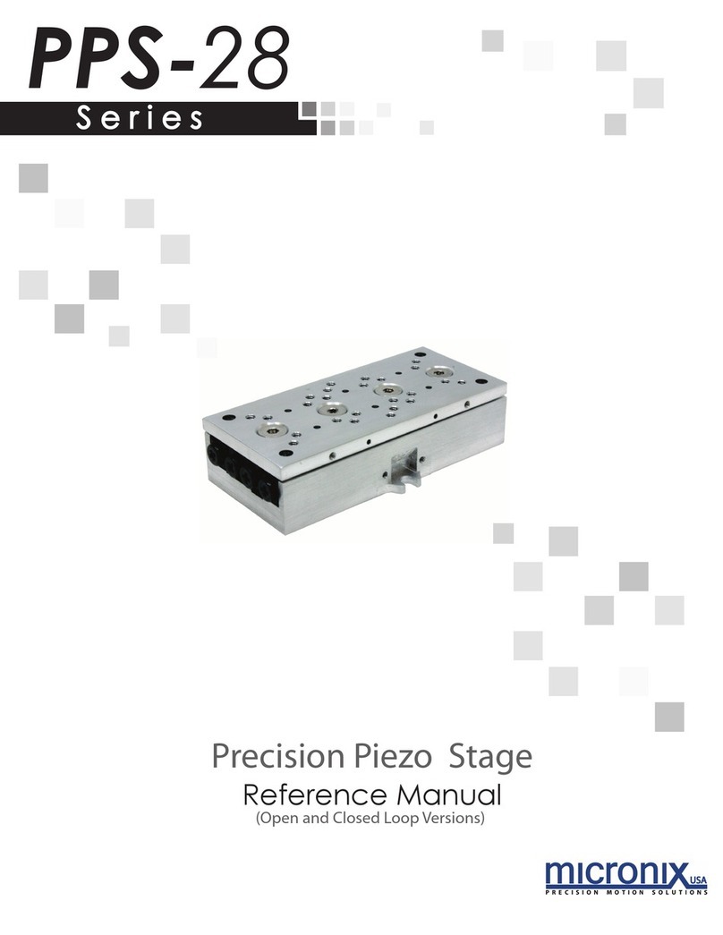
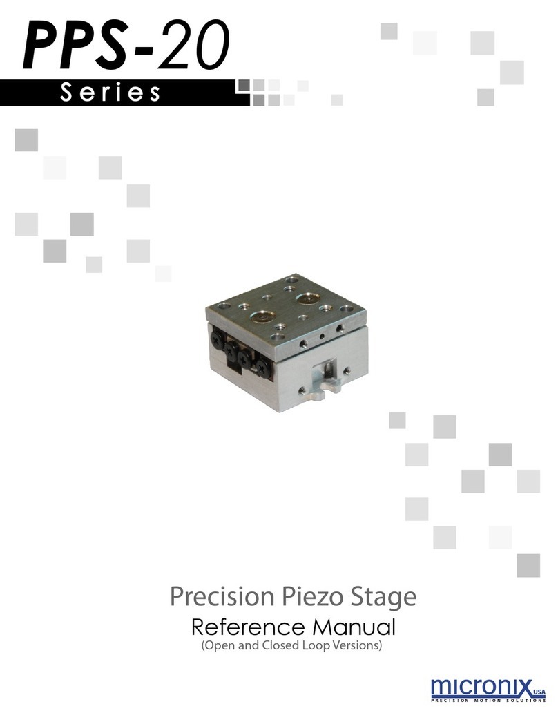
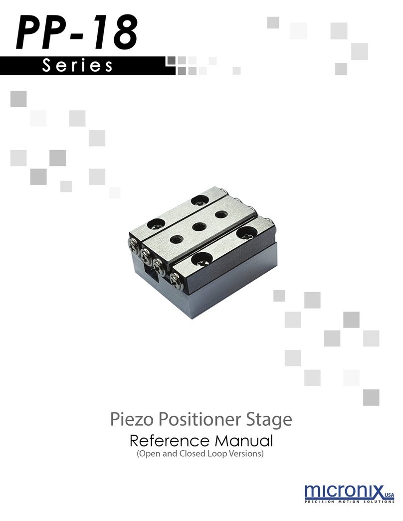
Micronix PPS-60 Series User manual

S e r i e s
Reference Manual
Precision Positioner Stage
(Open and Closed Loop Versions)
PPS-60

PPS-60
Precision
Positioner Stage
Reference Manual
Rev 1.04
MICRONIX USA, LLC
15375 Barranca Parkway, E-106
Irvine, CA 92618
Tel: 949-480-0538
Fax: 949-480-0538
Email: [email protected]
http://micronixusa.com

PPS-60 Precision Positioner Stage
Rev: 1.04
MICRONIX USA,LLC
Irvine, California
www.micronixsusa.com
1
Reference Manual
Contents
1. Introduction 3
1.1 Product Description 3
1.2 Recommended Controllers 4
1.3 Technical Data 4
1.4 Load Characteristics 4
2. Model configurations 5
2.1 PPS-60 Order Numbers 5
3. Preparing to Install the PPS-60 6
3.1 Installation Preparation 6
3.2 Package Contents 6
4. Installing the PPS-60 7
4.1 PPS-60 Installation 7
4.1.1 General Mounting 7
4.1.2 X-Y Mounting 11
5. Connecting the PPS-60 12
5.1 Atmospheric Environments 12
5.1.1 Open Loop Installation & Wiring Diagram 12
5.1.2 Closed Loop/Encoder Installation & Wiring Diagram 13
5.1 Vacuum Environments 15
5.1.1 Handling and Preparation 15
5.1.2 Open loop Installation & Wiring Diagram 15
5.1.3 Closed Loop/Encoder Installation & Wiring Diagram 16
6. Dimensions 18
6.1 PPS-60 Internal Motor Versions 18
6.2 PPS-60 External Stepper Motor Versions 19
7. Stacking Configurations 20
7.1 Configuration Examples 20
8. Supplementary Information 23
8.1 Maintenance 23
8.2 Units and Conventions 23
8.3 Accessories 23
A. Appendix 24
A.1 Stepper Motor 24
A.1.1 Standard Atmospheric DB-9 Male Motor Connector 24

PPS-60 Precision Positioner Stage
Rev: 1.04
MICRONIX USA,LLC
Irvine, California
www.micronixsusa.com
2
Reference Manual
A.1.2 Stepper Motor Specifications 24
A.2 Linear Motor 25
A.2.1 Standard Atmospheric DB-9 Male Motor Connector 25
A.2.2 Linear Motor Specifications 25
A.3 Piezo Motor 26
A.3.1 Standard Atmospheric DB-9 Male Motor Connector 26
A.3.2 2 Phase Piezo Motor Wiring Connections 26
A.4 Limit Switches 27
A.5 Open Loop Vacuum Wiring Diagram 28
A.5.1 Straight Through 9-Pin Feed Through 29
A.6 Using an Analog Encoder 30
A.6.1 Analog Encoder Overview 30
A.6.2 Encoder Pin-out 30
A.6.3 Operating and Electrical Specifications 30
A.6.4 Analog Output (Pins 1,2,6, and 7) 30
A.6.5 Index Window (Pins 3) 30
A.6.6 Resolution 30
A.6.7 Analog Encoder Wiring Diagram 31
A.6.8 Straight Through 15-Pin Feed Through 32
A.7 Using the Digital Encoder Module 33
A.7.1 36BEncoder Module Pin-out 33
A.7.2 Operating and Electrical Specifications 34
A.7.3 Output Signals & Signal Termination for A quad B, Index and limits 34
A.7.4 Resolution 34
A.7.5 MII 6000 Digital Wiring Diagram 35
A.7.6 Straight Through 25-pin Feed Through 36
A.8 Using a Micro Tape (Low Cost) Digital Encoder 37
A.8.1 Micro Tape Encoder Overview 37
A.8.2 Encoder Pin-out 37
A.8.3 Operating and Electrical Specifications 38
A.8.4 Output Signals 38

PPS-60 Precision Positioner Stage
Rev: 1.04
MICRONIX USA,LLC
Irvine, California
www.micronixsusa.com
3
Reference Manual
PPS-60 100mm with External Stepper Motor option
(Shown in center position)
PPS-60 50mm with Internal Stepper Motor option
(Shown in center position)
PPS-60 100mm with Piezo Motor option
(Shown in center position)
PPS-60 100mm with Linear Motor option
(Shown in center position)
Covered Versions Available Upon Request
1. Introduction
1.1 Product Description
The PPS-60 is a high-precision, linear stage which incorporates stepper, piezo, or
linear motors into the same form factor. Precision ball bearings assure high
stiffness and guiding accuracy for loads up to 150N (horizontal orientation). The
PPS-60 is available in standard travel lengths of up to 300mm, and an optional
linear encoder provides nanometer resolution. Vacuum and Ultra High
Vacuum (10-9 torr) versions are available. Longer travel and covered versions
are available upon request.
Features:
§Travel ranges of 25mm, 50mm, 100mm, 200mm, and 300mm (longer travel available
upon request)
§Load capacity up to 15kg
§Optional linear encoder

PPS-60 Precision Positioner Stage
Rev: 1.04
MICRONIX USA,LLC
Irvine, California
www.micronixsusa.com
4
Reference Manual
1.2 Recommended Controllers
The following controllers are available from MICRONIX USA:
§MMC-100 –Piezo
§MMC-110 –Piezo
§MMC-200 –Stepper
1.3 Technical Data
† -achievable with external stepper motor
1.4 Load Characteristics
Load Characteristics Fx[N] Fy[N] Fz[N] Mx[Nm]
My[Nm] Mz[Nm]
k
αx
[μrad/Nm]
k
αx
[μrad/Nm]
PM-003
10
100
150
10
10
10
100
100
SM-001 (internal)
10
100
150
10
10
10
100
100
SM-003 (external)
10
100
150
10
10
10
100
100
LM-002
10
100
150
10
10
10
100
100
Motor option PM-003 SM-001/SM-003 LM-002
Speed, max. [mm/sec]
10 10 (†15) 100
Encoder option Open Loop
Analog
(1 Vpp)
Digital
(RS-
422)
Digital
Low Cost
(RS-422)
Open Loop
Analog
(1 Vpp)
Digital
(RS-
422)
Digital
Low Cost
(RS-422)
Analog
(1 Vpp)
Digital
(RS-
422)
Digital
Low Cost
(RS-422)
Resolution, typical [μ
m]
0.001 0.01 0.0012
0.5 0.1 0.1 0.05 0.5 0.01 0.002 0.5
Repeatability,
bi-directional [µm]
-± 0.05
± 0.02 ± 1 ± 4 ± 0.1 ± 0.1 ± 1 ± 0.05
± 0.02 ± 1
Repeatability,
uni-directional [µm]
- 0.05 0.02 1 0.2 0.1 0.1 1 0.05 0.02 1
Accuracy [µm]
-
± 1
± 1
± 3
± 10
± 1
± 1
± 3
± 1
± 1
± 3

PPS-60 Precision Positioner Stage
Rev: 1.04
MICRONIX USA,LLC
Irvine, California
www.micronixsusa.com
5
Reference Manual
2. Model configurations
2.1 PPS-60 Order Numbers
*SM-001 internal standard installation on stages with 50mm or less travel.
SM-003 external standard installation on stages with 100mm or greater travel.
**Linear motor is not available with open loop or in vacuum environments.
***Only available with option 3 digital encoder.
† Only available with Piezo motor option or externally mounted UHV stepper motor.
‡Not available in vacuum environments.
╝Only available with Piezo motor.
Contact MICRONIX USA for custom applications and stacking configurations.
Order No. PPS-60-
Piezo Motor PM-003 1
Stepper Motor, SM-001* 2
Linear Motor, LM-002** 3
Stepper Motor, SM-003* 4
25mm Travel 1
50mm Travel 2
100mm Travel 3
200mm Travel 4
300mm Travel 5
None (Open Loop) 0
Analog (1Vpp) 2
Digital (RS-422) 3
Digital low cost, 0.5 m ‡4
No Limit Switch ╝0
Mechanical 1
Optical*** 2
Atmospheric 0
High Vacuum, 10-6 mbar 6
Ultra High Vacuum, 10
-9
mbar
†
9

PPS-60 Precision Positioner Stage
Rev: 1.04
MICRONIX USA,LLC
Irvine, California
www.micronixsusa.com
6
Reference Manual
3. Preparing to Install the PPS-60
3.1 Installation Preparation
When mounting the stage it is important to consider the flatness of the
mounting surface, as the stage will conform to the shape of that surface. A
surface that is not flat can adversely affect the performance and structural
integrity of the stage.
The stage is calibrated and guaranteed to be within specification at 20°C
±5°C, unless otherwise specified. The operating conditions of the stage are as
follows:
§Mount to a clean and flat surface which is free of debris, burrs, and dings
§An indoor atmosphere free of corrosive gases, excessive dust, and
condensation
§Temperature range of 0-40°C
§Relative humidity between 20-80%
§Locate away from water, heat, and electrical noise
3.2 Package Contents
If product is damaged or there are missing components, contact MICRONIX USA
immediately. Do not discard product packaging in case of return shipment.
Package Should Contain:
§PPS-60 Linear Stage
§Reference Manual
§Any other previously agreed upon components such as a controller

PPS-60 Precision Positioner Stage
Rev: 1.04
MICRONIX USA,LLC
Irvine, California
www.micronixsusa.com
7
Reference Manual
4. Installing the PPS-60
Mounting patterns require M3, M4, or 4-40 socket head cap screws or pan head
machine screws for mounting, as well as M2 x 6mm dowel pins for precision alignment.
Additional brackets and screws may be required for custom applications.
4.1 PPS-60 Installation
4.1.1 General Mounting
For general mounting configurations, mount the base to the mounting surface
using the thru holes. Move the carriage to access base mounting pattern. Note
that the 25mm version can only be mounted using the M4 Bottom Mount
method. (Please note, it is possible to move the carriage of the linear and piezo
motor configurations manually without damaging the stage, however, for
*stepper versions the motor must be driven by a controller to reposition the
carriage.)
4.1.1.1 Metric Mounting: M3 Top Mount
Travel
A
[mm]
25mm
75
50mm
75
100mm
125
200mm
225
300mm
325
Requires:
2x M2 x 6mm Dowel Pins
4x M3 Socket Head Cap Screws
(Low Profile recommended)
1. Move carriage via controller*, if
necessary, to access four
mounting holes. Insert Pins and M3
SHCS as shown.
Metric M3 Top Mount Mounting Pattern
w
For internal motor configurations: Mounting screws must be flush with base surface.

PPS-60 Precision Positioner Stage
Rev: 1.04
MICRONIX USA,LLC
Irvine, California
www.micronixsusa.com
8
Reference Manual
4.1.1.2 Metric Mounting: M4 Bottom Mount
Travel
A
[mm]
25mm
75
50mm
75
100mm
125
200mm
225
300mm
325
Metric M4 Bottom Mount Mounting Pattern
Requires:
2 x M2 x 6mm Dowel Pins
4 x M4 Socket Head Cap Screws
Insert Pins and M4 SHCS as shown.

PPS-60 Precision Positioner Stage
Rev: 1.04
MICRONIX USA,LLC
Irvine, California
www.micronixsusa.com
9
Reference Manual
4.1.1.3 Mounting to Metric Optical Table (25mm x 25mm spacing)
w
Assuming 25mm optical table hole spacing.
w
Check manufacturing tolerances of the optical table for precision fit.
w
For internal motor configurations: Mounting screws must be flush with base surface.
Travel
A
[mm]
25mm
75
50mm
75
100mm
125
200mm
225
300mm
325
Requires:
2x M2 x 6mm Dowel Pins
4x M3 to M6 Thread Adapters
4x M3 Socket Head Cap Screws
(Low Profile recommended)
1. Move carriage via controller*, if
necessary, to access four
mounting holes. Insert Thread
Adapters and M3 SHCS as shown.
Metric Optical Table Mounting Pattern

PPS-60 Precision Positioner Stage
Rev: 1.04
MICRONIX USA,LLC
Irvine, California
www.micronixsusa.com
10
Reference Manual
4.1.1.4 Mounting to Imperial Optical Table (1" x 1" spacing)
w
Assuming 25.40mm [1 inch] optical table hole spacing.
w
Check manufacturing tolerances of the optical table for precision fit.
w
For internal motor configurations: Mounting screws must be flush with base surface.
Travel
A
mm [in]
25mm
50.8 [2]
50mm
50.8 [2]
100mm
101.6 [4]
200mm
203.2 [8]
300mm
304.8 [12]
Imperial Base Mounting Pattern
Requires:
2 x M2 x 6mm Dowel Pins
4 x 4-40 Pan Head Machine Screws
4x 1/4 - 20 to 4-40 Thread Adapters
(Low Profile recommended)
1. Move carriage via controller*, if
necessary, to access two mounting
holes. Insert Thread Adapters and 4-40
Pan Head Machine Screws as shown.
2. Move carriage via controller*, if
necessary, to access remaining two
mounting holes. Insert 4-40 Pan Head
Machine Screws as shown.

PPS-60 Precision Positioner Stage
Rev: 1.04
MICRONIX USA,LLC
Irvine, California
www.micronixsusa.com
11
Reference Manual
4.1.2 X-Y Mounting
For additional mounting configurations see Section 7: Stacking Configurations.
Note that the 25mm version has to be factory mounted. (Additionally, please
note that it is possible to move the carriage of the linear and piezo motor
configurations manually without damaging the stage, however, for stepper
versions the motor must be driven by a controller to reposition the carriage.)
For internal motor configurations: Mounting screws must be flush with base
surface.
Direction
of Travel
Requires:
2 x M2 x 6mm Dowel Pins
4 x M3 Socket Head Cap Screws
(Low Profile recommended)
Move carriage via the
controller*, if necessary, to
access mounting holes.

PPS-60 Precision Positioner Stage
Rev: 1.04
MICRONIX USA,LLC
Irvine, California
www.micronixsusa.com
12
Reference Manual
5. Connecting the PPS-60
5.1 Atmospheric Environments
For controller information refer to the appropriate MMC controller manual.
Wiring diagrams are consistent for all piezo, stepper, and linear motor assemblies.
5.1.1 Open Loop Installation & Wiring Diagram
Connecting the PPS-60 in an open loop configuration only requires that the D-
sub 9 Pin Motor Cable be connected to a compatible controller. No other
cables or components are required. Please note, open loop configurations are
only available for stepper or piezo motor versions (See Appendix A.1 or A.3 for
pinout configurations).
External Version
Internal Piezo and Stepper Versions

PPS-60 Precision Positioner Stage
Rev: 1.04
MICRONIX USA,LLC
Irvine, California
www.micronixsusa.com
13
Reference Manual
5.1.2 Closed Loop/Encoder Installation & Wiring Diagram
Using the PPS-60 stage with an encoder requires a closed loop compatible
controller that recognizes the proper type of encoder feedback. Connect the
stage as shown below.
5.1.2.1 Analog or Low Cost Digital Encoder Wiring Diagram
Internal Piezo, Linear, and Stepper Versions
External Version

PPS-60 Precision Positioner Stage
Rev: 1.04
MICRONIX USA,LLC
Irvine, California
www.micronixsusa.com
14
Reference Manual
5.1.2.2 MII 6000 Digital Encoder Wiring Diagram
Internal Piezo, Linear, and Stepper Versions
External Version

PPS-60 Precision Positioner Stage
Rev: 1.04
MICRONIX USA,LLC
Irvine, California
www.micronixsusa.com
15
Reference Manual
5.1 Vacuum Environments
5.1.1 Handling and Preparation
When preparing the stage for vacuum environments, take the necessary
precautions (such as wearing gloves, clean room, clothing, etc.) when
handling the stage as to avoid any contaminants. Maximum Bake-out
temperature is 100°C. MICRONIX USA can supply the stage with vacuum
compatible connectors: 9-pin female PEEK connector for open loop, 15-Pin
female PEEK connector for closed loop with analog encoder, 25-pin female
PEEK connector for closed loop with MII 6000 digital encoder.
5.1.2 Open loop Installation & Wiring Diagram
Connecting an open loop PPS-60 in a vacuum chamber requires the use of a
feed through connector at the vacuum chamber wall. The vacuum
compatible PPS-60 will be supplied with wiring for a straight through feed
through, not a cross over gender changer. MICRONIX USA supplies test
connectors that simulate the vacuum feed through to allow for functionality
testing prior to installation in a vacuum chamber. Note: Linear motor versions
and low cost digital encoder versions are not available for vacuum
environments. For details regarding the pin-out and feed through specifications
see the Appendix section A.5.
Internal Piezo and Stepper Versions
External Version
Temporary test
connectors are
standard. Requires
customer supplied
feed through
connector

PPS-60 Precision Positioner Stage
Rev: 1.04
MICRONIX USA,LLC
Irvine, California
www.micronixsusa.com
16
Reference Manual
5.1.3 Closed Loop/Encoder Installation & Wiring Diagram
Closed loop installation of the PPS-60 stage in vacuum environments requires
an intermediate feed through connector at the vacuum chamber wall that
can accommodate both the motor cable, and the encoder cable.
The vacuum compatible PPS-60 will be supplied with wiring for a straight
through feed through, not a cross over gender bender. MICRONIX USA supplies
test connectors that simulate the vacuum feed through to allow for
functionality testing prior to installation in a vacuum chamber. For details
regarding the pin-out and feed through specifications see the Appendix
sections A.6.7, A.7.5.
5.1.3.1 Analog Encoder Wiring Diagram
Internal Piezo and Stepper Versions
External Version
Temporary test
connectors are
standard. Requires
customer supplied
feed through
connector

PPS-60 Precision Positioner Stage
Rev: 1.04
MICRONIX USA,LLC
Irvine, California
www.micronixsusa.com
17
Reference Manual
5.1.3.2 MII 6000 Digital Encoder Wiring Diagram
Internal Piezo and Stepper Versions
External Version
Temporary test
connectors are
standard. Requires
customer supplied
feed through
connector

PPS-60 Precision Positioner Stage
Rev: 1.04
MICRONIX USA,LLC
Irvine, California
www.micronixsusa.com
18
Reference Manual
6. Dimensions
6.1 PPS-60 Internal Motor Versions
Travel
[mm]
A
[mm]
B
[mm]
C
[mm]
D
[mm]
25 117 95 50.8
75
50 142 120 50.8
75
100 192 170 101.6
125
200 292 270 203.2
225
300 392 370 304.8
325
Table of contents
Other Micronix Valve Positioner manuals
Popular Valve Positioner manuals by other brands

Burkert
Burkert 2510 operating instructions

Pepperl+Fuchs
Pepperl+Fuchs PXV F200-B25-V1D Series manual

Pepperl+Fuchs
Pepperl+Fuchs PCV F200-B16-V15 Series manual

Samson
Samson 3780 series Mounting and operating instructions

Festo
Festo CMSX-P-S-A1-C-U-F1-D series operating instructions

Probotix
Probotix COMET Assembly procedure