MICROWELL DRY 300 PLASTIK User manual

MODEL: DRY 300/400/500 PLASTIK
WALL-MOUNTED SWIMMING POOL DEHUMIDIFIER
USER´S MANUAL

lDo not manipulate with the device with wet hands.
lDo not spray any flammable substances into the equipment; this might lead to fire.
lDo not clean the device with water.
lDo not clean the equipment with aggressive cleaning agents, this might lead to damage or deformations.
lWhen cleaning plastic parts do not use any cleaning agents unsuitable for the cover of the dehumidifier (household
cleaning agents, solvents, bleaching agents, benzene, diluents, rough cleaning powder, cresol, chemical agents).
Instead, sweep the dehumidifier cover with a soft cloth or a sponge.
lNever throw or insert any objects into any hose or opening.
lThe cover is made of plastic. Do not manipulate with lighted cigarette, cigarette ashes, or any other kind of fire in
vicinity to this part.
lUse this device exclusively for the intended purpose, as described in the attached instruction manual. Do not use
parts which are not recommended.
lNever block the air opening of the product. Protect the air openings from clogging by particles, hair etc.
lWhen the device is not running correctly (smoke, smell etc.), shut down the device by a circuit breaker in the
switchboard.
lRepair and dislocation must be performed exclusively by a service technician.
lBefore cleaning the device, switch off the circuit breaker in the switchboard.
lDo not place any objects onto the device.
lWhen you do not intend to use the device for a longer time, switch off the circuit breaker.
WALL-MOUNTED SWIMMING POOL DEHUMIDIFIER - USER´S MANUAL
Thank you for your decision to purchase our device.
Please read this user manual carefully before switching on the device.
Please keep the instructions in this practical guide for your quick know-how.
We do not take responsibility or warranty in case of damage, loss or impairment caused by incorrect usage,
or by usage for other purposes not described in this manual.
Contents: 1. Safety measures
2. Specifications for use
3. Instructions for use
4. Instructions for maintenance
5. Servicing the unit
6. Installation guide
7. Technical data
1. SAFETY MEASURES
2. SPECIFICATIONS FOR USE
The units are designed especially for use in indoor swimming pools, spas and saunas. They can also be very useful in laundries,
drying rooms and elsewhere.
2
The Microwell DRY 300 PLASTIK is designed for halls with a swimming pool surface area of up to 30 m .
2
The Microwell DRY 500 PLASTIK is designed for halls with a swimming pool surface area of up to 60 m .
The condition for using the unit is maintaining the room temperature within the range between a minimum of 22°C and
a maximum of 35°C. Ideally, the air in the room should be 2-3 °C warmer than the water in the swimming pool.
Microwell DRY 400 PLASTIK is designed for rooms with a swimming pool, which surface is up to 45 m².
2
INTAKE GRID
HYGROSTAT
UNIT COVER
EXHAUST GRID

The built-in humidistat is located at the bottom of the unit, on the left. The built-in hygrostat reads the humidity of the incoming air
and, depending on the set value, does or does not switch the compressor on. In the central position of the regulator, the unit secures
the average relative humidity of 60%. In indoor swimming pool halls, the correct air humidity should range from 55 to 65%.
Decreasing the humidity under this range is not desirable either from the physiological viewpoint or from the viewpoint of protection
of the building. Moreover, it increases the electricity consumption. The humidistat can be controlled by the user.
A view at the hygrostat scale
3.2. Remote control
On demand a dehumidifier can be controlled by remote humidistat & thermostat DRY EASY 300. If so, User’s manual is
attached to this Manual.
3. INSTRUCTIONS FOR USE
3.1. Humidity control by means of the built-in humidistat
3
WALL-MOUNTED SWIMMING POOL DEHUMIDIFIER - USER´S MANUAL
Under the inside cover of the unit, there is a two-position fan mode switch. In the first position, the fan runs even if the compressor
of the appliance has stopped: continuous operation of the fan. In the second position, the fan only runs simultaneously with the
compressor: periodical duty of the fan. The continuous operation mode of the fan is preferable, since the humidity reader built in
the device continuously reads humidity, and therefore a greater accuracy is reached. At the same time, continuous operation of the
fan results in better air circulation in the room. The installation work supplier selects the mode of the fan according to the request of
the user.
3.3. Control of the fan
Switch of the fan operation
Continuous duty of the fan
Periodical duty of the fan

4
WALL-MOUNTED SWIMMING POOL DEHUMIDIFIER - USER´S MANUAL
Under the inside cover of the unit, there is a two-position fan mode switch. In the first position, the fan runs even if the compressor
of the appliance has stopped: continuous operation of the fan. In the second position, the fan only runs simultaneously with the
compressor: periodical duty of the fan. The continuous operation mode of the fan is preferable, since the humidity reader built in
the device continuously reads humidity, and therefore a greater accuracy is reached. At the same time, continuous operation of the
fan results in better air circulation in the room. The installation work supplier selects the mode of the fan according to the request of
the user.
3.3. Control of the fan
Switch of the fan operation
Start-up of the compressor is, due to its protection, delayed by 3 minutes. Depending on the humidity of the environment, it may
take even longer for compressor to start operating. Once the compressor stops operating, the operation is renewed automatically,
at the earliest after three minutes. The user must not handle the setting element of the delay-action relay.
3.4. Control of the compressor
It is necessary to make sure that the suction inlet and the exhaust outlet are not covered. It is forbidden to place towels or clothing
items onto the exhaust outlets to dry them. The unit's cover can be cleaned with standard cleaning agents using a soft cloth or
a sponge. If water dripping out of the unit, please check the condensed water drain and make sure the pipe is not obstructed.
At least once a year, it is necessary to have the unit checked and cleaned by a service specialist. This is inevitable to secure a long
service life of the unit. We do not recommend the user to clean the interior elements of the unit, as this might cause a damage to the
unit. The unit contains mobile elements and live elements, therefore the interior parts may only be cleaned by a certified electrician
trained to service refrigerating appliances.
The unit must be installed in compliance with the local installation and electrical installation regulations !
6.1. Location of the unit
The unit is to be installed on the wall or on the mobile stand. To ensure the right operations of the dehumidifier and its maximum
efficiency in terms of humidity control, it is necessary to ensure proper air circulation into and from the dehumidifier. This requires
the actual unit placement appropriately into the swimming pool hall respecting basic prerequisites of air circulation and air flow. It is
strictly forbidden to install the unit just below the ceiling. At least 200mm of a free space must be kept above the unit and at least
150mm below the unit. Each swimming pool hall is individual thus a special care needs to be taken to choose a proper dehumidifier
placement. It is forbidden to install the unit on the ground. It is also strictly forbidden to block the air inlet and outlet with any
objects (canoe, buckets, ceiling beams, etc.). For maintenance purposes please keep free space of 200mm on both sides
of the dehumidifier.
4. MAINTENANCE INSTRUCTIONS
5. SERVICING THE UNIT
6. INSTALLATION GUIDE
Continuous duty of the fan
Periodical duty of the fan

5
WALL-MOUNTED SWIMMING POOL DEHUMIDIFIER - USER´S MANUAL
The units have a self-supporting structure and are remarkably easy to install.
A part of the unit accessories is also an installation bracket, which must be fixed onto the wall. The axis of the fixation openings is
210 mm lower than the top edge of the unit. The fixation openings are 420 mm apart (DRY 300/400 PLASTIK) or 360 mm apart
(DRY 500 PLASTIK). Once the bracket is mounted to the wall, it is possible to mount the unit without disassembling its cover.
6.2. Mounting the unit
Model DRY 300/400 PLASTIK
Model DRY 500 PLASTIK
The cover can be dismounted after releasing two screws (DRY 300/400) or three screws (DRY 500) at the bottom of the unit.
Release the screws, pull the bottom part of the cover toward yourself and then, by lifting it shortly, rake down the cover from the
rear plate. To mount the cover, carry the procedure out in reverse order.
6.3. Dismounting and mounting the cover
The unit is designed in such a way that it can be securely mounted and will hold in its place even if lifted accidentally. In the top
edges of the back plate, there are screw holes for safety screws, which are accessible after dismounting the front fibreglass cover.
Arrows indicate the safety screw holes in the back plate. A safety screw is fastened through a screw hole in the back plate into a wall
plug in the wall. This will prevent the unit from being accidentally pulled out and falling off the mounting bracket. At the same time,
it will secure the perpendicular position of the unit and align the unit with the wall.
6.4. Securing the position of the unit
TOP EDGE OF THE UNIT
BRACKET SPIRIT LEVEL
MOUNTING HOLES
BACK PLATE
SAFETY SCREW HOLES
TOP EDGE OF THE UNIT
BRACKET SPIRIT LEVEL
MOUNTING HOLES

6
WALL-MOUNTED SWIMMING POOL DEHUMIDIFIER - USER´S MANUAL
Condensed water is drained from the unit by the force of gravity. It is necessary to situate the unit in such a way that there is
sufficient declivity for the drainage of condensed water. The condensation product must be drained through a siphon into a sewer or
into the outside environment. It is strictly forbidden to drain the condensed water back into the swimming pool, as it may be
polluted by bacteria. A pipe for condensate drainage is led out at the bottom of the unit, on the left. This pipe is to be inserted into a
sewerage pipe with the inside diameter of at least 18 mm.
6.5. Drainage of condensate
CONNECTIONS ARE VALID FOR MODELS DRY 300/400 PLASTIK AS WELL DRY 500 PLASTIK - FRONT VIEW
Connection of the unit onto the mains must conform to relevant safety standards. Connection requirements: Power supply: 220-
240V / 50Hz. Protection: 10A (DRY 300/400 PLASTIK) or 16A (DRY 500 PLASTIK) by a protective switch with nominal differential
drop-out current not exceeding 30 mA. The unit's terminal board for connection onto the electric mains is situated on the left hand-
side of the unit. The main switch of the unit must be situated outside of the swimming pool hall. The main switch of the unit must be
bipolar, with switch-out breaking of conductors L and N. An appliance for disconnecting the unit from the mains must be embedded
into a firm surface. The distance of contacts, when swithched off, must be at least 3 mm for all poles. The connection of the
appliance to the electric mains must be carried out by a certified electrician.
6.6 Connection of the unit onto the mains
An example of preparation of electric power supply, condensate drainage
and mounting of the bracket
ATTACHMENT OF THE HEATER ELEMENT TO THE DISTRIBUTION
OF THE HEATING WATER
THREAD G ½ '’ MALE
OPTIONS LOCATION OF CONNECTION
POWER SUPPLY
2
CYSY WIRE 3C x 1.5 (3C x 2.5) mm
(FROM THE REAR)
117
117
50
15
35
50
100
35
40
50
CONDENSATE DRAINAGE (FROM THE REAR)
PIPING WITH MINIMUM INTERNAL DIAMETER OF 18 mm
A1 - FROM LEFT SIDE
A2 - FROM RIGHT SIDE
A3 - FROM BACK SIDE

7
WALL-MOUNTED SWIMMING POOL DEHUMIDIFIER - USER´S MANUAL
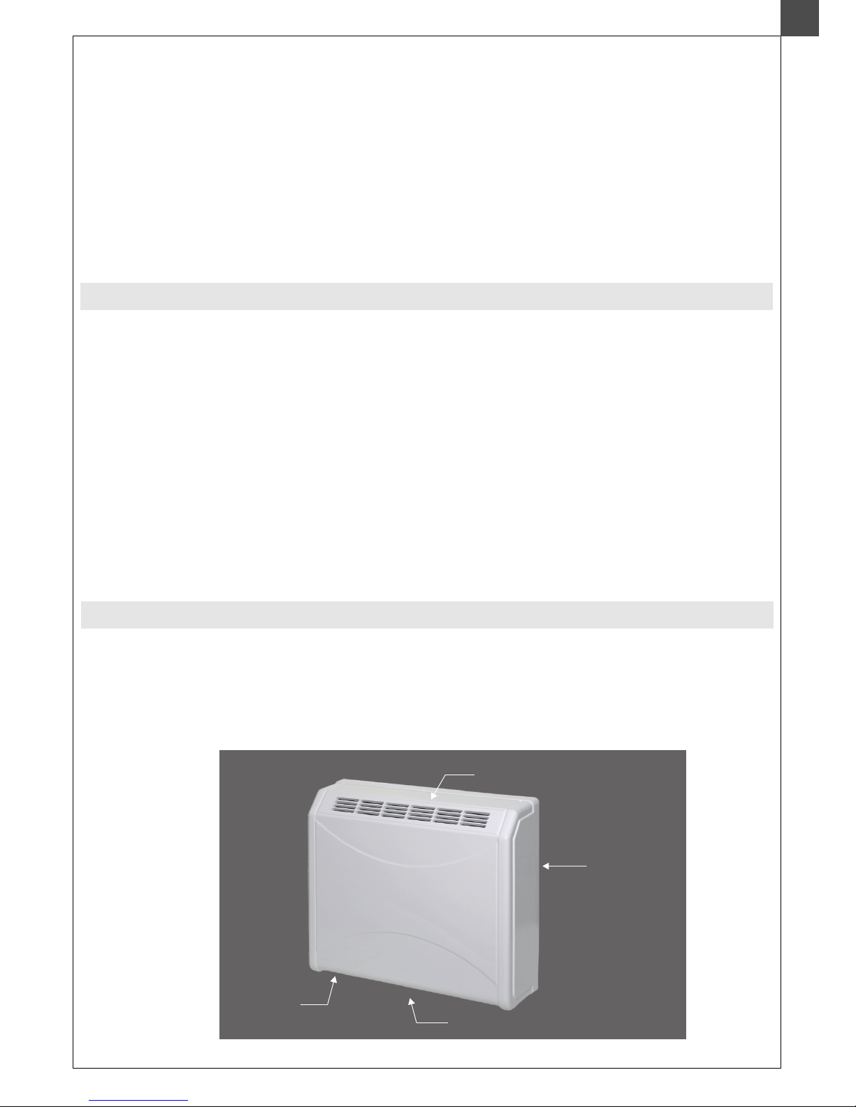
LOCATION OF THE EQUIPMENT
ZONE 1, IPX4
ZONE 2, IPX2
OUTSIDE THE ZONES
In the distance of 1250 mm or less
from the swimming pool edge, the
bottom edge of the unit must be in
the height of 2500 mm from the
swimming pool surface; if it is
embedded under the floor, then
2500 mm from the floor.
At least 1250 mm (i.e. out of the reach of the hand) from the lateral edge
of the wash basin, in the minimum height of 1200 mm above ground. It
cannot be placed above the wash basin.
In the distance of at least 1500 mm
from the vertical plane around the
jumping platforms, diving boards
and 2500 mm above the highest
surface, where persons are likely to
stay.
If the unit is in the distance of less
or equal to 1250 mm horizontally
from the edge of the swimming
pool, then it must be raised up to
the height of 2500 mm from the
swimming pool surface; if the
pool is embedded under the floor,
then the unit must be raised up to
the height of 2500 mm from the
floor.
It is inevirable to locate the unit outside the zones, where cleaning by jet water is supposed. Connection of the unit to the mains and
its protection must correspond with the applicable standards. Electrical supply of the unit must be carried out by a protective
isolating transformer or it must be protected by a current protective switch with a nominal differential cut-off current not exceeding
30 mA.
SWIMMING POOL
The location must be in compliance with the HD 384.7.702 S1, IEC 60364-7-702 standard.
It is recommended to situate the unit outside zones 0, 1 and 2.
In case the unit is situated into zones 2 or 1, it must be adhered to the HD, IEC standard.
SWIMMING POOL
Swimming pools which are not
cleaned by jet water
in the distance of 1250 to 2000 mm from the swimming pool edge,
the unit must adhere to the HD, IEC standard and in the height
of at least 300 mm from the floor
Swimming pools which
are not cleaned by jet water
In the distance of 2000 to 3500 mm
from the swimming pool edge, the
unit must adhere to the HD, IEC
standard and a minimum 150 mm
elevation above the ground is
required for sufficient air flow.
Installing the unit on the floor is
prohibited.
At least 1250 mm (i.e. out of the reach of the hand)
from the lateral edge of the shower cabinet. It cannot
be placed above the shower cabinet.
OUTSIDE THE ZONES OUTSIDE THE ZONES

8
WALL-MOUNTED SWIMMING POOL DEHUMIDIFIER - USER´S MANUAL
The LPHW heater elements are supplied only to order. Connection of the hot water heater element onto the LPHW plumbing is
carried out similarly to the installation of radiators. On the feeder pipe, it is connected by a control valve and on the return pipe by a
closing screw joint. The LPHW is not supplied with a control valve and a screw joint; these are supplied by the supplier of the
heating.
6.7. LPHW heater element - to order
Attachment threading of the hot water heating element Attachment of the heater element to the distribution of the heating water
After installing the LPHW plumbing and leading the LPHW into the element under pressure, it is necessary to bleed the heater
element. The bleeding valve is located on the feeder pipe of the LPHW heater element. To secure that the LPHW heater element
works always at full heat output, blowing onto the unit by a fan must be provided even when no dehumidification is being
performed. Therefore, when using the LPHW heater element, the switch of fan operation must be switched into the position of
continuous operation.
6.9. Mounting behind the wall - on demand
The dehumidifiers are simply adapted also to installation behind the wall into the adjacent room. In such case, only two grids are
visible in the swimming pool area. These are the same grids which are, in the basic configuration, installed on the dehumidifier's
cover. In the configuration for installation behind the wall, conduit adapters are screwed onto the dehumidifier's cover. The
adapters are delivered for passage through the wall of the length of 400 mm. In the place of installation, they are shortened from
the side of the swimming pool as necessary.
View from the adjacent room View from the swimming pool hall
THREAD G ½ '’ MALE
OPTIONS LOCATION OF CONNECTION
117
117
50
15
35
50
100
35
40
50
CONDENSATE DRAINAGE (FROM THE REAR)
PIPING WITH MINIMUM INTERNAL DIAMETER OF 18 mm
A1 - FROM LEFT SIDE
A2 - FROM RIGHT SIDE
A3 - FROM BACK SIDE
POWER SUPPLY
2
CYSY WIRE 3C x 1.5 (3C x 2.5) mm
(FROM THE REAR)
6.8. Hot gas defrost - on demand
Hot gas defrost allows the dehumidifier to operate effectively at air temperatures down to 5°C. The gas circuit is equipped with 4-
way valve. When temperature on evaporator drops below zero, system starts to count 30 minutes of time. After this period the
evaporator temperature is checked again and if the current temperature is still below zero, a compressor and a ventilator are turned
off. Gas circuit is reversed and after 3 min a compressor starts. System now defreezes the unit for 3 minutes. After another 3
minutes, if the defrost cycle is completed, the unit goes into usual operations. In extremely low temperatures and in still humid
enough air it is normal to take 2 or 3 defreezing cycles to complete the procedure.
NOTE: It is normal for a compressor to turn itself off and on again during defreezing cycle.

9
WALL-MOUNTED SWIMMING POOL DEHUMIDIFIER - USER´S MANUAL
Your compressor is protected for the transport with plastic zipper strap. Due to compressor size and weight this is necessary in
order to have a fully functional unit delivered to you safely. This protection must be removed before starting the unit. Please view
below pictures on how to proceed. The procedure generally takes few seconds. Please be advised that no removal of plastic zipper
strap results in warranty void.
6.10. Compressor transport protection (DRY 500 PLASTIK only)
Picture 1: Plastic zipper strap as
delivered from factory. Picture 2: To cut the strap use
pliers or other appropriate tool. Picture 3: Finally remove the
strap from the the dehumidifier.

WALL-MOUNTED SWIMMING POOL DEHUMIDIFIER - USER´S MANUAL
7. TECHNICAL DATA
PIPING 615x65mm - DRY 300 PLASTIK
(PIPING 1075x65mm - DRY 500 PLASTIK)
FLANGED CONNECTION
R100
ELBOW 135° 615x65mm - DRY 300 PLASTIK
(ELBOW 135° 1075x65mm - DRY 500 PLASTIK)
25 mm WIDE FLANGE
DEHUMIDIFIER
R100
SHORTEN THE PIPING AS NECESSARY
PIPING 615x65mm - DRY 300 PLASTIK
(PIPING 1075x65mm - DRY 500 PLASTIK)
FLANGED CONNECTION
ELBOW 135° 615x65mm - DRY 300PLASTIK
(ELBOW 135° 1075x65mm - DRY 500 PLASTIK)
25 mm WIDE FLANGE
SHORTEN THE PIPING AS NECESSARY
MOUNTING FROM INSIDE: REINFORCE THE PIPING TO THE VALUE OF 65 MM
AND FROM THE OUTER SIDE - PUR FOAM HAS TO BE GLUED TO THE MASONRY.
AFTER HARDENING OF THE PUR FOAM, REMOVE THE FORTIFICATION AND
MOUNT THE GRID.
MOUNTING FROM INSIDE: REINFORCE THE PIPING TO THE VALUE OF 65 MM
AND FROM THE OUTER SIDE - PUR FOAM HAS TO BE GLUED TO THE MASONRY.
AFTER HARDENING OF THE PUR FOAM, REMOVE THE FORTIFICATION AND
MOUNT THE GRID.
DRY 300/400 PLASTIK
DRY 500 PLASTIK
300/400 PLASTIK
500 PLASTIK
130
227
428
83
DATA UNIT
DRY 300 DRY 400 DRY 500
For swimming pools with max. water surface m2 30 45 60
Exctraction rate at 30°C and 60 % RH l/24hrs 36 48 66
Exctraction rate at 30°C and 70 % RH l/24hrs 43 53 83
Exctraction rate at 30°C and 80 % RH l/24hrs 47,5 58 101
Operational temperature - standard °C 22-35 22-42 22-35
Operational temperature - antifreeze stat °C 15-35 15-42 15-35
Operational temperature - Thermostatic expansive valve (TEV) °C 22-42 - 22-42
Operational temperature - antifreeze stat + TEV °C 15-42 - 15-42
Operational temperature - hot gas defrost °C 5-35 - 5-35
Operational humidity range % RH 20-100 20-100 20-100
Air flow m3/h 550 550 800
Noise level (in 1m distance) dB (A) 42 42 44
Heat output W 1900 1900 3500
Energy consumption W 700 700 1000
Voltage V/Hz/f 230/50/1 230/50/1 230/50/1
Operating / Starting current A 3.1 / 15 3.1 / 15 4,5
Protection A 10 10 16
Conductor mm2 CYSY 3C x 1,5 CYSY 3C x 1,5 CYSY 3C x 2,5
Condensed water pipe mm d 18 d 18 d 18
Dimensions netto (width x height x depth) mm
PLASTIK (780 x 660
x 255 ),
METAL&SILVER
(780 x 642 x 300)
PLASTIK (780 x 660
x 255 ),
METAL&SILVER
(780 x 642 x 300)
PLASTIK (1245 x
660 x 255 ),
METAL&SILVER
(1245 x 642 x 300)
Dimensions brutto (width x height x depth) mm 850 x 735 x 345 850 x 735 x 345 1315 x 735 x 345
Weight netto / brutto kg PLASTIK 40/ 46 kg,
METAL 50 / 56 kg
PLASTIK 40/ 46 kg,
METAL 50 / 56 kg
PLASTIK 60 / 69 kg,
METAL 77 / 86 kg
Amount of refrigerant - R 410 A kg 0,5 0,5 0,75
Max. pressures in the system HP/LP bar 28,5/8,5 28,5/8,5 28,5/8,5
868
998
10

WALL-MOUNTED SWIMMING POOL DEHUMIDIFIER - USER´S MANUAL
OUTPUT DIAGRAM OF DEHUMIDIFICATION (DRY 300 PLASTIK)
Dehumidification output
Relative humidity
Dehumidification output
Air temperature
OUTPUT DIAGRAM OF DEHUMIDIFICATION (DRY 500 PLASTIK)
Air temperature
Relative humidity
80%
70%
60%
50%
40%
80%
70%
60%
50%
40%
0
10
20
30
40
50
60
15 20 25 30 35
(l/24h)
(°C)
0
20
40
60
80
100
120
15 20 25 30 35
(l/24h)
(°C)
OUTPUT DIAGRAM OF DEHUMIDIFICATION (DRY 400 PLASTIK)
Dehumidification output
Air temperature
Relative humidity
11

WALL-MOUNTED SWIMMING POOL DEHUMIDIFIER - USER´S MANUAL
DIMENSIONS DRY 300/400 PLASTIK
DIMENSIONS DRY 500 PLASTIK
FRONT VIEW
VIEW FROM BELOW
SIDE VIEW
FRONT VIEW
VIEW FROM BELOW
SIDE VIEW
BRACKET
BRACKET
ATTACHMENT OF THE LPHW HEATER ELEMENT TO THE DISTRIBUTION
OF THE HEATING WATER
- (MODELS WITH THE LPHW HEATER ELEMENT ONLY)
THREAD G ½ '’
ATTACHMENT OF THE LPHW HEATER ELEMENT TO THE DISTRIBUTION
OF THE HEATING WATER
- (MODELS WITH THE LPHW HEATER ELEMENT ONLY)
THREAD G ½ '’
THE POSITION AGAINST GETTING LOOSE FROM
THE BRACKET
(FROM THE REAR)
THE POSITION AGAINST GETTING LOOSE FROM
THE BRACKET (FROM THE REAR)
THE POSITION AGAINST GETTING LOOSE FROM
THE BRACKET (FROM THE REAR)
THE POSITION AGAINST GETTING LOOSE
FROM THE BRACKET (FROM THE REAR)
CONDENSATE DRAINAGE (FROM THE REAR)
PIPING WITH MINIMUM INTERNAL DIAMETER OF 18 mm
CONDENSATE DRAINAGE (FROM THE REAR)
PIPING WITH MINIMUM INTERNAL DIAMETER OF 18 mm
POWER SUPPLY
2
CYSY WIRE 3C x 1.5 mm
(FROM THE REAR)
POWER SUPPLY
2
CYSY WIRE 3C x 2.5 mm
(FROM THE REAR)
12

WALL-MOUNTED SWIMMING POOL DEHUMIDIFIER - USER´S MANUAL
WIRING DIAGRAM OF MODEL MICROWELL DRY 300/400 PLASTIK
DRY 300 BASIC
Note: Producer reserves right to make changes on wiring.
DRY 300/400
Standard
DRY 300/400
EASY 200 /
HYG 6001
DRY 300/400
LPHW / Solenoid
Wiring diagram
BASIC
1
2
13

WALL-MOUNTED SWIMMING POOL DEHUMIDIFIER - USER´S MANUAL
DRY 300.1
Note: Producer reserves right to make changes on wiring.
14

WALL-MOUNTED SWIMMING POOL DEHUMIDIFIER - USER´S MANUAL
DRY 300.2
Note: Producer reserves right to make changes on wiring.
15

WALL-MOUNTED SWIMMING POOL DEHUMIDIFIER - USER´S MANUAL
WIRING DIAGRAM OF MODEL MICROWELL DRY 500 PLASTIK
DRY 500 BASIC
Note: Producer reserves right to make changes on wiring.
DRY 500 Standard
DRY 500
EASY 200 /
HYG 6001
DRY 500 LPHW /
Solenoid
Wiring diagram
BASIC
1
2
16

WALL-MOUNTED SWIMMING POOL DEHUMIDIFIER - USER´S MANUAL
Note: Producer reserves right to make changes on wiring.
DRY 500.1
17

WALL-MOUNTED SWIMMING POOL DEHUMIDIFIER - USER´S MANUAL
Note: Producer reserves right to make changes on wiring.
DRY 500.2
18

WALL-MOUNTED SWIMMING POOL DEHUMIDIFIER - USER´S MANUAL
19

WALL-MOUNTED SWIMMING POOL DEHUMIDIFIER - USER´S MANUAL
EXPANDED VIEW OF MODEL MICROWELL DRY 300/400 PLASTIK
EXPANDED VIEW OF MODEL MICROWELL DRY 500 PLASTIK
Position Component Number of
pieces
1 Fiberglass cover 1
1,1 Inlet grid SMH2 20 1075 x 75 1
1,2 Outlet grid SMH2 12.5 1075 x 75 1
2 Back metal sheet 1
3 Ventilator metal sheet 1
4 Metal sheet in front of the exchanger 1
5 Metal sheet above the exchanger 1
6 Metal sheet under the compressor 1
7 Electro-box metal sheet 1
8 Compressor cover 1
9 Evaporator tray 1
10 Compressor tray 1
11 Exchanger 400 - evaporator 1
12 Exchanger 650 - condenser 1
13 Ventilator EBM D4-E133-DL01-D6 1
14 Compressor DAIKING YZG-E24RAY2 1
15 Low pressure valve Ranco HR00001 A5R703 1
16 Filter 20g d4/6mm 1
17 Filling valve, pipe d6, thread SAE 1/4" 2
18 Sunction pipe d10mm 1
19 Pressure pipe d6mm 1
20 Screw ST4.8 x 38 2
21 Screw 3.5 x 13 9
24 Rubber grommet d15 DA 110/150/10 4
25 Rubber grommet d30 DA 230/300/20 4
26 Condensate pipe d18x3, 1m 1
Position Component Number of
pieces
1 Fiberglass cover 1
1,1 Inlet grid SMH2 20 1005 x 65 1
1,2 Outlet grid SMH2 12.5 1075 x 65 1
2 Back metal sheet 1
3 Metal sheet in front of the exchanger 1
4 Metal sheet above the exchanger 1
5 Metal sheet under the compressor 1
6 Ventilator metal sheet 1
7 Electro-box metal sheet 1
8 Holding metal sheet for ventilator 1
9 Compressor cover 1
10 Evaporator tray 1
11 Compressor tray 1
12 Exchanger 720 - evaporator 1
13 Exchanger 1115 - condenser 1
14 Ventilator EBM K4E146-AB73-21 1
15 Compressor DAIKING YZG-E35RY2 1
16 Low pressure valve Ranco HR00001 A5R704 1
17 Filter 30g d6/6mm 1
18 Filling valve, pipe d6, thread SAE 1/4" 2
19 Sunction pipe d10mm 1
20 Pressure pipe d6mm 1
21 Screw ST3.5 x 13 9
22 Screw ST4.8 x 38 3
25 Rubber grommet d30 DA 230/300/20 7
26 Rubber grommet d15 DA 11d180/10 4
27 Condensate pipe d18x3, 1m 1
20
Other manuals for DRY 300 PLASTIK
3
This manual suits for next models
2
Table of contents
Other MICROWELL Dehumidifier manuals

MICROWELL
MICROWELL DRY 500 User manual

MICROWELL
MICROWELL DRY 300 PLASTIK User manual

MICROWELL
MICROWELL DRY 300 PLASTIK User manual

MICROWELL
MICROWELL DRY 1200 METAL User manual

MICROWELL
MICROWELL DRY 800 METAL User manual

MICROWELL
MICROWELL DRY 300 SILVER Guide

MICROWELL
MICROWELL DRY 300 User manual

MICROWELL
MICROWELL DRY 1200 METAL User manual

MICROWELL
MICROWELL T90 User manual

MICROWELL
MICROWELL DRY 800 METAL User manual