5
Condensed water is drained from the device by the force of gravity. It is necessary to locate the device in a way that enables
sufficient condensed water gradient. The condensate must be delivered through a siphon into the sewer or into the outside
environmemt. It is strictly forbidden to deliver the condensate back into the swimming pool, as it may be bacterially contaminated.
There is a tube for condensed water delivery located at the bottom of the device, on the left side. This tube must be plugged into
a sewerage pipe with an internal diameter min. 18 mm.
6.4. Condensate drain
SWIMMING POOL DEHUMIDIFIER - USER´S MANUAL
The cover can be disassembled by releasing of two screws located at the side parts of the device. Release the screws, pull the
bottom part of the cover toward yourself and then, by lifting it shortly, rake down the cover from the rear plate. The unit installation
is performed in an adverse way.
6.3. Dismounting and mounting of the cover
The unit must be installed in compliance with the local installation and electrical installation regulations !
6.1. Unit location
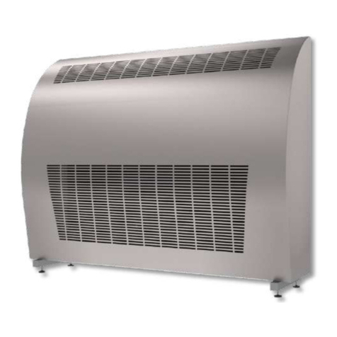
The unit is to be installed on the floor or on the wall. To ensure the right operations of the dehumidifier and its maximum efficiency in
terms of humidity control, it is necessary ensure proper air circulation into and from the dehumidifier. This requires the actual unit
placement appropriately into the swimming pool hall respecting basic prerequisites of air circulation and air flow. It is strictly
forbidden to install the unit just below the ceiling. At least 200mm of a free space must be kept above the unit. Each swimming pool
hall is individual thus a special care needs to be taken to choose a proper dehumidifier placement. It is also strictly forbidden to block
the air inlet and outlet with any objects (canoe, buckets, ceiling beams, etc.). For maintenance purposes please keep free space of
200mm on both sides of the dehumidifier.
6. INSTALLATION GUIDE
The equipment has a self-supporting construction and is very easy to install.
There is an elevated adjustable stand included in the equipment accessories.
6.2. Equipment fixation
The compressor´s operation starting is for securing its protection, delayed by min. 3 minutes. Depending on the humidity of
environment, it may last even longer. The user must not manipulate with the setting element of a time relay.
3.3. Compressor regulation
It is necessary to make sure that the intake and exhaust outlets are not covered. It is forbidden to place towels or other clothes
on the exhaust outlets to dry them. Cleaning of the device´s cover is allowed only by using non-abradant cleaning agents. In case
there is a water dripping from the equipment, please check whether a condensate pipe is not obstructed.
At least once a year, it is necessary to have the unit checked and cleaned by a service specialist. This is necessary in order to secure a
long operational life of the device. Cleaning the interior parts of the device by a user is not recommended, as this may lead to a
damage on the unit. The device contains mobile elements as well as elements under electrical pressure, therefore the interior parts
can be cleaned only by a certified electrician with an appropriate knowlegde of refrigerating technology.
4. MAINTENANCE INSTRUCTIONS
5. SERVICING THE UNIT
600
280
50
90
50
95
50
60
POWER SUPPLY/FROM BACKSIDE/
- CYSY WIRE 3C x 2.5 mm2
CONDENSATE DRAINAGE (FROM BACKSIDE)
PIPING WITH MINIMUM INTERNAL DIAMETER OF 18 mm
LOCATION OF CONNECTION /FROM BACKSIDE/
THREAD G ½ '’ MALE
