MICROWELL DRY 800 METAL User manual

POOL
DEHUMIDIFIER
Installation and user manual
Version: 01/2022
Model: DRY 800 METAL
DRY 1200 METAL

Installation and user manual DRY 800/1200 Metal
V01/2022| 2
Contents
Thank you, for purchasing a Microwell swimming pool dehumidifier. You
have probably chosen the best and most energy efficient dehumidifier for
your pool. Before you use this device, it is necessary to carefully read the
entire Installation and user manual. It is not allowed to commence the heat
pump installation or operation unless full content of this Installation and
user manual is understood and acknowledged. Please keep the Installation
and user manual available in the case of any future reference is required.
Please provide this information also to each user of the device. Please
mind local regulations in your country regarding installation and usage of this heat pump which are
valid in addition to this User manual.
1. WASTE DISPOSAL INFORMATION............................................................................................................. 3
2. SAFETY MEASURES................................................................................................................................... 3
2.1 ELECTRICAL SAFETY ..................................................................................................................................... 3
2.2 USAGE PRECAUTIONS .................................................................................................................................. 4
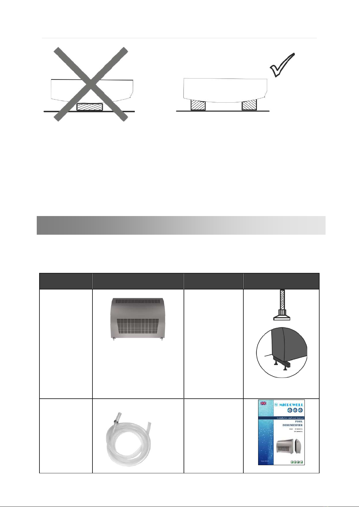
2.3 HANDLING PRECAUTIONS ............................................................................................................................. 5
3. PRODUCT DESCRIPTION ........................................................................................................................... 6
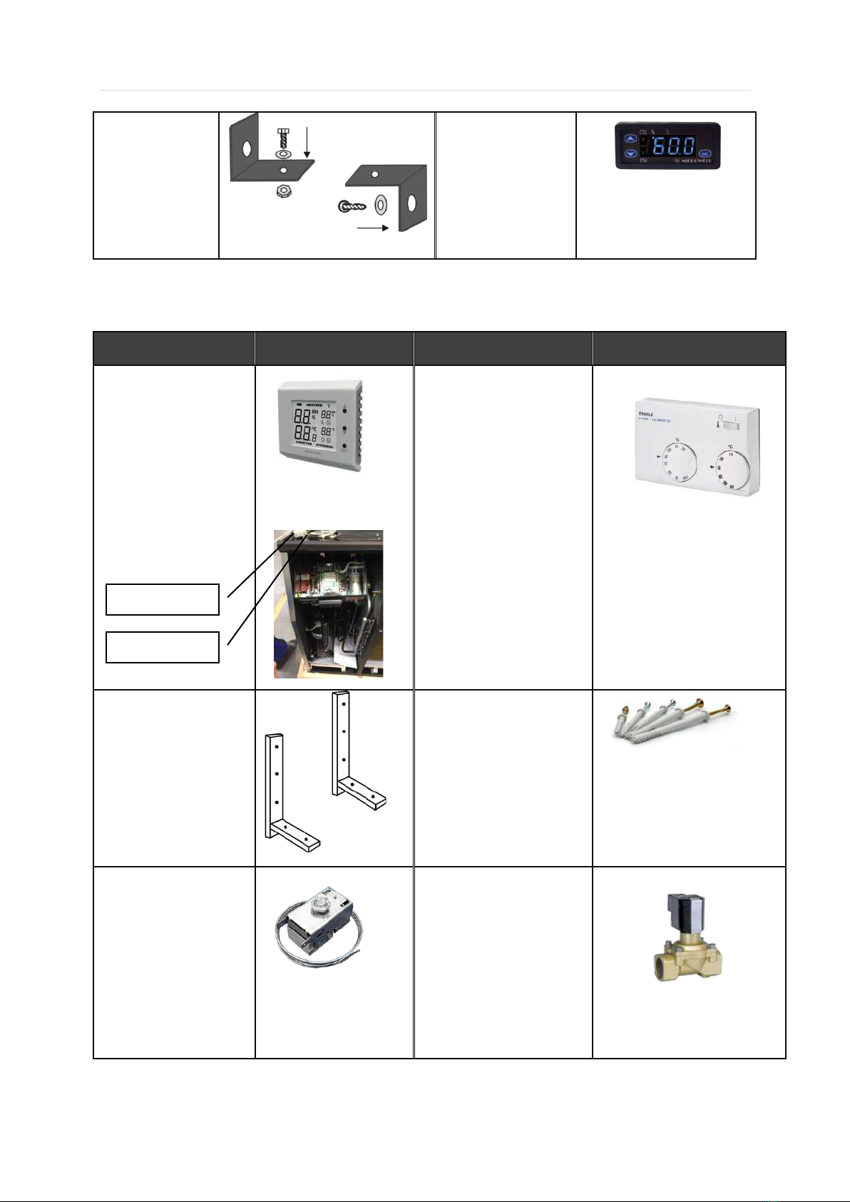
3.1 DESCRIPTION OF BASIC PARTS........................................................................................................................ 9
3.2 FRESH AIR SUPPLY (ON DEMAND AS ACCESSORY) ............................................................................................... 9
4. HANDLING INSTRUCTIONS ..................................................................................................................... 10
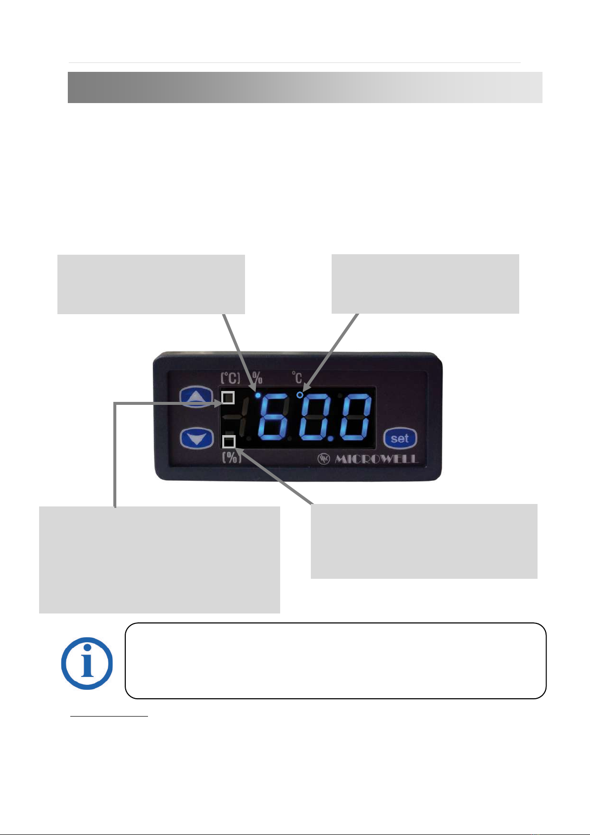
4.1 MAIN HUMIDISTAT ................................................................................................................................... 10
4.2 BACKUP HUMIDISTAT................................................................................................................................. 15
4.3 HUMIDITY CONTROL BY REMOTE CONTROLLER -ON DEMAND............................................................................ 15
4.4 HUMIDITY CONTROL BY EXTERNAL WIRED HUMIDISTAT EBERLE ........................................................................ 18
4.5 FAN REGULATION...................................................................................................................................... 18
4.6 COMPRESSOR REGULATION......................................................................................................................... 19
5. INSTALLATION MANUAL ........................................................................................................................ 19
5.1 LOCATING THE DEVICE ............................................................................................................................... 20
5.2 INSTALLATION OF DEVICE............................................................................................................................ 22
5.3 CONDENSATE DRAIN.................................................................................................................................. 33
5.4 MAIN POWER SUPPLY CONNECTION.............................................................................................................. 35
5.5 LPHW HOT WATER INSERT FOR ADDITIONAL HEATING –ON DEMAND ................................................................. 39
5.6 ELECTRIC HEATING .................................................................................................................................... 41
5.7 AIR FILTER –ON DEMAND........................................................................................................................... 42
6TECHNICAL DATA ................................................................................................................................... 45
6.1 TECHNICAL DATA CHART*........................................................................................................................... 45
7SUMMER SHUTDOWN ........................................................................................................................... 56
7.1 TROUBLESHOOTING –SAVE TIME AND MONEY................................................................................................ 56
7.2 MAINTANANCE INSTRUCTIONS .................................................................................................................... 57
7.3 CLEANING BY SUPERCLORING ...................................................................................................................... 57
7.4 OPERATION DURING CONSTRUCTION ............................................................................................................ 57
7.5 MICROLIGHT+ ........................................................................................................................................ 57
8WARRANTY CONDITIONS....................................................................................................................... 59

Installation and user manual DRY 800/1200 Metal
V01/2022| 3
1. WASTE DISPOSAL INFORMATION
If you are using the heat pump in Europian countries, you must follow these instructions:
DISPOSAL: Do not dispose this product as unsorted municipal waste. It is prohibited to
dispose this heat pump in domestic / household waste. It is prohibited to dispose this
appliance into forests or natural landscape. This could lead into local soil pollution.
Collection of such waste must be treated individually.
DISPOSAL POSSIBILITIES:
1. The municipality has established a collection system where electronic waste can be
disposed.
2. When buying a new product, the retailer or the manufacturer may take back the old
appliance free of charge.
3. Old appliance may contain valuable resources which could be sold to scrap material dealers.
4. Disposal of packaging materials such as carton box or plastic / bubble foil can be recycled.
Please use your local waste separation services.
2. SAFETY MEASURES
The device is primarily designed for use in indoor swimming pools, smaller pools, spas or saunas.
Alternative use is in laundries, drying rooms or other humid areas requiring dehumidification. See the
technical data table to check model suitability for a pool room and pool area.
It is necessary to follow the instructions in this Installation and user manual and local regulations
in your country that regulate the installation and usage of this device. Incorrect, improper or
operations contradictory to this User´s manual may lead to injury or property damage and will
lead to loss of warranty. To prevent injury or property damage the following instructions must be
followed:
2.1 Electrical safety
•The device operates at dangerous electrical current.
•Only authorized persons with particular electro-technical qualification can manipulate with unit.
•Danger of electrical shock.
•Do not exceed the required power supply.
•Do not turn a device that shows signs of possible damage such as broken packaging, broken or
otherwise damaged unit’s chassis or cover, smoke, smell, damaged power cord etc. on.
•It is necessary to use appropriate Residual current circuit breaker (RCD) for connection of the
dehumidifier to main power supply.
•Do not manipulate device with wet hands.
For proper and optimal operation of this device, it is necessary to keep the air temperature in
the pool hall 2 - 3 ° C higher than the actual water temperature in the pool. It is also necessary
to maintain the air temperature in the pool hall within the operating temperature range of the
dehumidifier (specified in the Technical Data section), based on the specific selection of the
operating temperature of the accessories selected for the specific equipment. Lower air
temperatures outside the operating temperature range can damage the device due to freezing.
Higher temperatures outside the operating temperature range may damage the unit due to
overheating of the unit.
WARNING !

Installation and user manual DRY 800/1200 Metal
V01/2022| 4
•Do not clean device with water.
•Before cleaning the device, unplug the power cord and switch off the circuit breaker of the unit’s power
supply.
•Installation, service or repair must be performed by a qualified technician.
•When the device is not intended to be used for a longer time, we recommend switching the circuit
breaker of the unit’s power supply off.
•Unit must be installed in vertical position to avoid condensate water to enter electrical part of the unit.
•It is forbidden to install the unit close to devices that may cause electrical or frequency disturbance
such as welding machines, motors or rotors, WIFI/WLAN routers or repeaters.
•It is forbidden to alter electrical installation of the device. It is also forbidden to alter any other part or
functionality of the device.
2.2 Usage precautions
•Do not cover or block the intake or exhaust openings. It is forbidden to block or cover the intake or
exhaust openings with clothes, towels, buckets, canoes, ceiling beams, etc.
•Do not install or place any heating appliances close to intake grilles / louvers. It could
continually overheat the dehumidifier and result in its malfunction or damage.
•Do not climb or sit on the unit.
•Do not place any objects on the top of the unit (e.g. boxes, flower vases, etc.)
•Never push or push any objects into any hose or hole.
•Do not spray any flammable substances on the device, as this may cause a fire.
•Do not clean the device with aggressive cleaning agents, which may damage or deform the unit.
•The cover of the METAL dehumidifier model is made of three-layer anti-corrosion-protected steel,
with a silver metallic or white surface color.
•Use the device only for the purpose for which it was manufactured, as described in the instruction
manual. Do not use parts that are not recommended.
•Do not drink or otherwise use condensate that has been aspirated by the unit. Do not return water
to the pool. Water can be contaminated with bacteria.
•Children are not allowed to operate, touch or play with the unit.
•Children are not allowed to handle the packaging, plastic / bubble foil. Risk of suffocation!
•Prevent children from being injured or injured by handling the unit, its parts, or its packaging.
Small parts, such as the screws can be swallowed by children and cause injury.
•Do not leave the children in the swimming pool hall unattended.
•Do not dry wet towels or swimsuits
on the unit and do not put other objects
on top of it (e.g. boxes, vases with
flowers, etc.).

Installation and user manual DRY 800/1200 Metal
V01/2022| 5
2.3 Handling precautions
•Transport in a horizontal position or overturning the unit may damage the compressor, which may result in
malfunction or damage to the unit and will void the warranty.
•The device must be handled carefully and with special care to avoid mechanical damage.
•It is forbidden to exert any unsuitable mechanical force on the unit, which may cause mechanical damage to
the device
•It is forbidden to freely drop the device on the ground or any hard or rough surface that can lead to a hard
impact of the device and scratch the cover. As the owner of the area make sure that your installer does not
damage the cover or a part of the device during handling and installation.
Keep in vertical
position for 2 hours
Leave the unit in a vertical upright position for at least
2 hours before mounting. It is necessary to stabilize
the refrigerant charge and especially to return the oil
to the compressor tray. Oil could get out of the tray
during t
ransport and handling, and this could
adversely affect the function of the dehumidifier.
Beware of scratches. Handle the
device carefully. Avoid contact with
surfaces that may scratch the
device.

Installation and user manual DRY 800/1200 Metal
V01/2022| 6
•Please notify your reseller or distributor if the delivered unit had been damaged. The unit may appear to
work fine at first, but minor damage may cause the unit to stop working properly in a short time. In this case the
unit must be inspected and its further use must be approved by the seller.
•Please notify your reseller or distributor if you notice immediately after installation that the unit is not
working properly.
•In case of device failure resulting from improper handling or mechanical damage (impact, hit, fall, etc.), the
manufacturer reserves the right to evaluate the continuity of warranty.
3. PRODUCT DESCRIPTION
The unit was delivered in a carton box on a wooden palette. Please unpack the unit and check the
content. It should include the following:
Package:
Name/ code
Image
Name/ code
Image
1 - Dehumidifier
1x
2 – Metal feet /
adjustable screw with
plastic heel /
4x
3 – Condensate
drain hose
(illustration photo)
1x
4 - Installation and
user manual
1x

Installation and user manual DRY 800/1200 Metal
V01/2022| 7
5 – Adjusting "L"
piece
2x
+ screw M6 – 2x
+ nut MC – 1x
+ washer D7 – 2x
6- Built-in digital
humidistat and
thermostat
Additional accessories (to order):
Name/code
Image
Name/ code
Image
1 - External wireless
humidistat and thermostat
DRY EASY 300
1x
Part of packaging (white
box) located on the fan
plate on the left
2 - External wired humidistat
EBERLE
Separate small box glued to
the device (cardboard box)
see picture 1
3 – Wall console
2x
4 – Fixing screws for a cross
screwdriver D6 and dowels
D10 (illustration photo)
4x
5 – Defrost thermostat
6 - Solenoid valve - valve and
coil
1x
Part of packaging (white box)
located under the main cover
on the fan plate on the left,
see. picture point. 1
Easy300 / Eberle
Solenoid valve

Installation and user manual DRY 800/1200 Metal
V01/2022| 8
7 – air filter
Installed inside the device
8 – fresh air supply adapter
List of necessary tools (is not part of packaging):
Názov/ kód
Obrázok
Názov/ kód
Obrázok
1 - Drill
1x
3 – Drill bit 10mm
1x
2 - Phillips
screwdriver
1x
Vacuum cleaner and
ladder
5 – Small hammer
1x
6 - Meter
1x
7- Spirit level
1x

Installation and user manual DRY 800/1200 Metal
V01/2022| 9
3.1 Description of basic parts
Legend:
1 – Air exhaust
2– Air suction
3– Mechanical humidistat (on the bottom)
4– Metal cover
5– Possible heating water supply from the right / left side ½ “(on request as accessory)
6– Possible heating water supply from the back ½ “(on request as accessory)
7– Fresh air supply Ø 100 mm (on request as accessory)
8 – Condensate drain Ø outer 20 mm ( Ø inner 16 mm)
9 – Power supply 230 V
10 - position (under the cover) of the connection box for the main power supply
11 - position (under cover) of the fan mode switch
12 - position of the cover fixing screws
13 - Built-in digital humidistat and thermostat
14 -Feet
15 - position of the nut for screwing the locking L-pieces to the wall
3.2 Fresh air supply (on demand as accessory)
Each MICROWELL DRY dehumidifier has the option of fresh air supply. The air supply is located below
the condenser, which effectively heats the incoming fresh air due to heat recovery.
The metal fresh air connection is supplied already mounted on the dehumidifier, but towards the
inside. When installing the dehumidifier, it is necessary to remove the flange to wind it correctly
(opposite to the one supplied). For example, a plastic pipe is then mounted on the flange, which
conducts the air through the wall.
1
2
1
7
2
12
5
6
8
9
4
10
11
15
13
12
14

Installation and user manual DRY 800/1200 Metal
V01/2022| 10
4. HANDLING INSTRUCTIONS
4.1 Main humidistat
The dehumidifier is switched on and off using a digital humidistat with a display. The built-in
humidistat is located in the housing of the device. The humidistat checks the humidity level of the
intake air and, depending on the set value, starts dehumidification if necessary. In rooms with an
indoor pool, the optimum humidity should be between 55% and 65%. Reducing the humidity level
below said interface is not desirable, taking into account the physiological aspects as well as the
protection of the building. In addition, electricity consumption increases. The humidistat can be fully
controlled by the user.
ERROR REPORTS:
Er1 Memory impairment. Switch the electrical connection off and then on again. If the fault
message persists, please contact us to replace the part.
0-E Sensor failure. The electrical connection of the sensor is interrupted. Please check the cable.
S-E Sensor failure. The sensor is shorted. Please check the cable.
The illuminated dot indicates
that the display shows the air
temperature.
The illuminated dot indicates
that the humidity level is shown
on the display.
The lit square indicates that the controller
is giving a signal to heat the air (if a hot
water insert and solenoid valve are
installed.) An unlit symbol indicates that
the desired air temperature is lower than
the actual one.
An illuminated square indicates that the
controller is giving signal to
dehumidify, ie. the required humidity is
lower than the actual one.
The manufacturer recommends setting the required humidity value in the range of 55 to 65% RH.
Reducing humidity below this range is not desirable either from a physiological point of view or
from a building protection point of view. In addition, it increases electricity consumption. Setting
above 65% RH can create an environment where the humidity reaches a critical level of 70%,
which could lead to an overgrowth of unwanted bacteria and the formation of mold, or damage

Installation and user manual DRY 800/1200 Metal
V01/2022| 11
User setting HUMIDITY / TEMPERATURE changing ( /* Manufacturer settings)
Press SET key for 10secs
User setting TEMPERATURE
changing menu
User setting HUMIDITY changing menu /*
TEMP./HUMI. display changing cycle setting menu
Save in memory
Return to operating mode
Temperature manufacturer setting
without LPHW /* with LPHW /*

Installation and user manual DRY 800/1200 Metal
V01/2022| 12
Deviation, correction and other service settings
Press SET key for 10secs
Displayed after 10 secs
Press SET button shortly
Displayed immediately
2
1
TEMPERATURE output type
select
HUMIDITY output type
select

Installation and user manual DRY 800/1200 Metal
V01/2022| 13
Program setting ( /* Manufacturer settings)
TEMPERATURE output type
Cooling
Heating /*
Change
TEMP. output delay
time setting
TEMP. output
hysteresis type select
TEMP. output
hysteresis setting
Temperature sensor
correction
Setting the device address for
communication with the
superior system via the RS485
interface
Communication speed setting
/RS485/
Program lock setting
Single.(+) hysteresis setting
Double(+/-) hysteresis
Setting /*
Change
Change
Change
Change
Unlock /*
Lock
1
/*
/*
/*
/*

Installation and user manual DRY 800/1200 Metal
V01/2022| 14
HUMIDITY output type select
Humidifying
Dehumidifying /*
HUMI. output delay
time setting
HUMI. output
hysteresis type select
HUMI. output
hysteresis setting
HUMI. sensor
correction
Sensor heating set
Change
Change
Change
Heating enable
Heating unenable /*
HUMIDITY / TEMP. display mode change
HUMI. display mode
HUMI./TEMP. diplay
mode
TEMP. display mode
2
Single.(+) hysteresis
setting /*
Double(+/-) hysteresis setting
/*
/*
/*

Installation and user manual DRY 800/1200 Metal
V01/2022| 15
4.2 Backup humidistat
Your dehumidifier is equipped with a built-in mechanical humidistat as standard. On request, it can
be equipped with an external wired humidistat, or an external wireless humidistat and thermostat. A
detailed description of the operation of these controllers is described in separate manuals, which are
part of their own packaging.
The mechanical humidistat is a reliable way of measuring and subsequently regulating the humidity
in your pool hall. Its advantage is it’s high reliability as it measures moisture based on the physical
properties of the measuring fiber. In the case of a mechanical humidistat, a hysteresis of 4% and a
maximum of 8% must be taken into account. Hysteresis is a property where the off or on is shifted to
a higher or lower relative humidity value than the actual desired one.
If you use an external (wired or wireless) humidistat, a mechanical humidistat also remains installed
in the device. It functions as a backup in case of failure of the external humidistat. In this case, the
mechanical humidistat is set to 70%. We recommend the user not to change this setting.
4.3 Humidity control by remote controller - on demand
An external wireless humidistat and thermostat DRY EASY 300 can be ordered for the pool
dehumidifier as standard equipped with a built-in digital humidistat and thermostat + mechanical
humidistat.
Wireless communication takes place in the 868 MHz band, where the emphasis is on the reliability
and range of the controller. The dehumidifier is controlled primarily by a remote humidistat,
When ordering the DRY EASY 300, there will be no digital humidistat and thermostat
1401F on the cover. The hole in the cover will be covered.
Picture:
Mechanical
humidistat
indicator wheel.
Humidity scale. DRY = continuous
dehumidification, STOP = stop
dehumidification. Values of 20-30-40-
50-60-70 correspond
to relative
humidity.
Humidistat setting ("V").
Currently, the humidistat in the
photo is set to 70%.
The built-in mechanical humidistat is located in the lower left part of the
device (under the cover of the dehumidifier). The humidistat checks the
humidity level of the sucked-in air and, depending on the set value,
starts or dehumidifies. Ideal humidity of a pool hall is 55-65%. Your
dehumidifier is primarily regulated by a built-in digital humidistat and
thermostat. The role of the mechanical humidistat (black wheel) is to be
a backup controller. Therefore, it is set to 70%. We do not recommend
changing this setting.
The manufacturer recommends setting the required humidity value on the backup
humidistat to the range of 70-80% RH. This will serve as a backup in case the digital
humidistat and thermostat 1401F located on the cover switches off. The recommended
setting of the digital humidistat and thermostat 1401F is in the range of 55 to 65% RH.

Installation and user manual DRY 800/1200 Metal
V01/2022| 16
provided that the built-in humidity controller in the dehumidifier is set to a higher desired humidity
value than the remote humidistat.
If the backup humidistat had been set to a lower value than the DRY EASY 300 remote humidistat,
the backup humidistat will take over the room humidity control and in this case the dehumidifier will
not respond to signals from the DRY EASY 300 remote humidistat.
The manufacturer recommends setting the required humidity value on the DRY EASY 300 in the
range of 55 to 65% RH.
External wireless humidistat and thermostat DRY EASY 300
1. TRANSMITTER 2. RECEIVER 3. ANTENNA
Broadcast indication
Additional functions and operation of the remote humidistat are described
in the separate enclosed instructions.
Battery status
indicator
Humidity
Temperature
Dehumidification
Indication of reaching/not
reaching required humidity
Indication of reaching/not
reaching required
temperature
Heating indicator

Installation and user manual DRY 800/1200 Metal
V01/2022| 17
Location of receiver and antenna
A: The receiver is located inside the electrical box and the antenna is located on the outside of the
electrical box.
B: For TTW version /through the wall/, we recommend pulling the antenna into
the pipe in the wall. Follow the picture below.
C: If your dehumidifier is also equipped with an electric heater, place
the antenna on the outside of the cover. After starting the
dehumidifier, test whether the signal is successfully transmitted
between the transmitter (display unit) and the antenna. For
example, if you set the humidity lower than the current value, then
the dehumidifier will start up into its full operation within 3 minutes.
The signal is designed to pass successfully over a distance of about
100 meters, through an aluminum fence or steel-reinforced concrete
wall. However, the individual conditions of a particular installation
may be different. If there is no signal transmission, place the
antenna in the lower (suction) air ducting.

Installation and user manual DRY 800/1200 Metal
V01/2022| 18
4.4 Humidity control by external wired humidistat EBERLE
If your device is equipped with an EBERLE wired remote humidity controller, pay attention to this
section of the installation manual.
The dehumidifier can be equipped with a remote humidistat on request. In this case, the
dehumidifier has two humidity controllers. One of them is a built-in mechanical humidistat inside the
pool dehumidifier, the other is an external wired humidistat. The dehumidifier is controlled primarily
by the remote humidistat, provided that the built-in humidity controller inside the dehumidifier is set
to a higher desired humidity value than the remote humidistat.
If your dehumidifier is equipped with a hot water insert and/or a solenoid valve also, you must use a
humidistat with an EBERLE HYG7001 thermostat to activate the dehumidifier’s air heating function,
or you must have an external thermostat connected.
4.5 Fan regulation
Under the inner cover of the device there is a two-position fan mode switch. In the first position,
the fan runs even if the compressor of the device does not, it is a so-called CONTINUOUS mode. In
the second position, the fan runs simultaneously with the compressor, it is a PERIODICAL mode.
The continuous operation mode of the fan is more optimal, as the humidity sensor built into the
device continuously senses the humidity, which achieves higher accuracy. At the same time, the
continuous operation of the fan mixes the air in the room better. The fan control is set by the
installation company according to the user's requirements. DRY800/1200 models are equipped with
two speeds. In the case of continuous operation, the fan still runs at full speed. In the case of
continuous operation while the compressor is switched off, the fan runs at low speed, which
effectively mixes the air in the pool hall.
CONTINUOUS DUTY OF THE FAN
PERIODICAL DUTY OF THE FAN
Wired humidistat EBERLE HYG6001
Wired humidistat and thermostat EBERLE
When ordering EBERLE HYG6001/7001, there will be no digital humidistat and
thermostat 1401F on the covers and the hole in the cover will be covered with a cover.

Installation and user manual DRY 800/1200 Metal
V01/2022| 19
4.6 Compressor regulation
The start of the compressor is delayed by 3 minutes due to it‘s protection. Depending on the
humidity and ambient temperature, this may take longer. If the compressor stops, it will start
automatically after 3 minutes at the earliest. The user must not manipulate the setting element of
this time protection. The task of time protection is to equalize the pressures of the refrigerant in the
dehumidifier‘s system.
5.INSTALLATION MANUAL
After a long period of inactivity, it is normal for the compressor to try to start 4-6 times
before finally turning on. It also depends on the current air temperature. A lower ambient
temperature (approx. 22°C) requires more attempts, a higher temperature (approx. 30°C)
usually requires only 1 attempt.
The appliance must be installed in accordance with national installation and
wiring regulations!
Please note that the screws and dowels supplied with the appliance may only be
used on a solid concrete or a brick wall. Please check the base material and select
suitable screws and dowels.
The location of the device must be in accordance with the STN 33 2000-7-702
standard. It is recommended to place the device outside zones 0,1 and 2. When
placing the device in zones 2 or 1, the STN must be observed.
It is necessary to place the device outside zones where cleaning with spraying
water is expected. Connection to the electric network and protection must comply
with relevant standards. The power supply of the device must be realized by a
protective isolating transformer or protected by a residual current device with a
rated residual breaking current not exceeding 30 mA when installed in rooms
where water can be found.

Installation and user manual DRY 800/1200 Metal
V01/2022| 20
5.1 Locating the device
MICROWELL DRY 800/1200 METAL are designed to be installed directly in the pool hall. All models
are protected by electrical protection class IP44.
ZONE 1, IPX4
ZONE 2, IPX2
OUTSIDE ZONE
at a distance of less than or equal to
1250 mm from the edge of the pool,
the lower edge of the device must be
at a height of 2500 mm from the
surface of the pool, if it is recessed
under the floor or from the floor.
min. 1250 mm (i.e. out of reach) from the side edge of
the
sink at a height of min. 1200 mm from the floor,
cannot be above the sink.
at a distance of min. 1500 mm
from the vertical plane around
the jumping platforms, jumping
boards and starting blocks and
2500 mm a
bove the highest
surface on which pe
ople are
expected to be present.
if the unit is at a distance less than or
equal to 1250 mm horizontally from
the edge of the pool, then it must be
lifted 2500 mm from the surface of
the pool, if it is recessed under
the
floor and from the floor.
POOL
POOL
Pools that are not cleaned
by
water jet
at a distance of 1250 to 2000 mm from the edge of the pool
they must comply with STN and at least 300 mm from the floor
.
at a distance of 2000 to 3500
mm from the edge of the pool
must be in accordance with STN
and is required min. 150 mm
elevation above the floor due to
sufficient airflow, installation of
the device on the floor is
prohibited.
min. 1250 mm (i.e. out of reach) from the side edge of
the shower enclosure, cannot be above the shower
enclosure.
OUTSIDE ZONE
OUTSIDE ZONE
Pools that are not cleaned
by
water jet
Other manuals for DRY 800 METAL
1
This manual suits for next models
1
Table of contents
Other MICROWELL Dehumidifier manuals

MICROWELL
MICROWELL DRY 300 PLASTIK User manual

MICROWELL
MICROWELL DRY 1200 METAL User manual

MICROWELL
MICROWELL T90 User manual

MICROWELL
MICROWELL DRY 300 PLASTIK User manual

MICROWELL
MICROWELL DRY 1200 METAL User manual

MICROWELL
MICROWELL DRY 300 SILVER Guide

MICROWELL
MICROWELL DRY 800 METAL User manual

MICROWELL
MICROWELL DRY 300 PLASTIK User manual

MICROWELL
MICROWELL DRY 300 PLASTIK User manual

MICROWELL
MICROWELL DRY 300 User manual