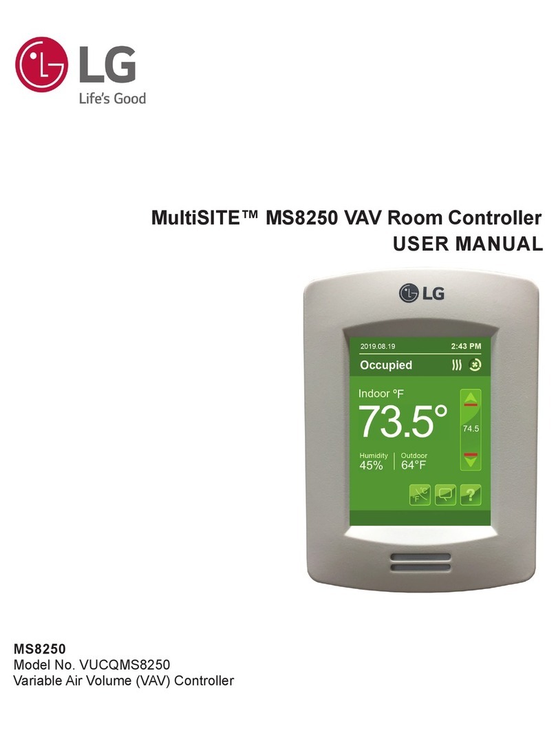
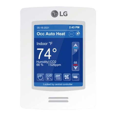
LG MultiSITE MS8000 Series User manual

MS8350
Model No. VUCQMS8350
Commercial and Hotel HVAC Fan Coil Controller
MS8650
Model No. VUCQMS8650
Rooftop Unit, Heat Pump, and Indoor Air Quality Controller
MultiSITE™ MS8000 Series Room Controllers
USER MANUAL

The instructions included in this manual must be followed to prevent prod-
uct malfunction, property damage, injury, or death to the user or other
people. Incorrect operation due to ignoring any instructions will cause
harm or damage. A summary of safety precautions begins on page 4.
Do not throw away, destroy, or lose this manual.
Please read carefully and store in a safe place for future reference.
Content familiarity required for proper installation.
For more technical materials such as submittals, engineering
databooks, and catalogs, visit www.lghvac.com.
For continual product development, LG Electronics U.S.A., Inc., reserves the right to change specifications without notice.
©LG Electronics U.S.A., Inc.
This document, as well as all reports, illustrations, data, information, and other materials are the property of LG Electronics U.S.A., Inc.
PROPRIETARY DATA NOTICE
This document, as well as all reports, illustrations, data, information, and
other materials are the property of LG Electronics U.S.A., Inc., and are
disclosed by LG Electronics U.S.A., Inc., only in confidence.

3
Due to our policy of continuous product innovation, some specications may change without notication.
©LG Electronics U.S.A., Inc., Englewood Cliffs, NJ. All rights reserved. “LG” is a registered trademark of LG Corp.
User Manual
TABLE OF CONTENTS
Safety Precautions ............................................................................. 4-5
Standards and Certications................................................................ 6
Introduction............................................................................................ 7
Disclaimer .............................................................................................. 8
HMI Display and Set Up ................................................................... 9-11
Customized Screens ...................................................................... 12-17
User HMI for Hospitality..................................................................... 12
User HMI for Commercial.................................................................. 13
Other Functions / Setpoint Adjustment for Heating Mode ................. 14
Heating Only Conguration / Setpoint Adjustment for Cooling Mode /
System Modes................................................................................... 15
Fan Mode Settings ............................................................................ 16
Customizable Color Options.............................................................. 17
User and Integrator Screens .............................................................. 18
Network Screens ............................................................................ 19-28
Network Settings ............................................................................... 19
ZigBee Network 1 / 2......................................................................... 20
ZigBee Network 2 / 2......................................................................... 21
BACnet Network Settings.................................................................. 22
BACnet Instance Number.................................................................. 23
Modbus Network Settings.................................................................. 24
Wi-Fi Network 1 / 4............................................................................ 25
Wi-Fi Network 2 / 4............................................................................ 26
Wi-Fi Network 3 / 4............................................................................ 27
Wi-Fi Network 4 / 4............................................................................ 28
Conguration Screens................................................................... 29-58
MS8350 Congurations 1 to 9...................................................... 29-41
MS8650 Congurations 1 to 11 .................................................... 42-58
Setpoints Screens .......................................................................... 59-62
MS8350 Setpoints 1 / 2 ..................................................................... 59
MS8350 Setpoints 2 / 2 ..................................................................... 60
MS8650 Setpoints 1 / 2 ..................................................................... 61
MS8650 Setpoints 2 / 2 ..................................................................... 62
Display Screens.............................................................................. 63-64
Display Screen 1 / 2 .......................................................................... 63
Display Screen 2 / 2 .......................................................................... 64
Service View Screens..................................................................... 65-81
MS8350 Service View Screens 1 to 8 .......................................... 65-72
MS8650 Service View Screens 1 to 9 .......................................... 73-81
Test Outputs Screens..................................................................... 82-83
Test Outputs Screen 1 / 2 .................................................................. 82
Test Outputs Screen 2 / 2 .................................................................. 83
Language Selection Screens.............................................................. 84
Language Selection Screens 1 / 4 to 4 / 4......................................... 84
Schedule Screens........................................................................... 85-88
Clock - Schedule Menu ..................................................................... 85
Clock.................................................................................................. 86
Schedule............................................................................................ 87
Options .............................................................................................. 88
ADR Screen.......................................................................................... 89
Wireless Screens............................................................................ 90-96
Wireless Menu Options ..................................................................... 90
Ecosystem Settings........................................................................... 91
Device Groups................................................................................... 92
Device X ....................................................................................... 93-94
Temperature Alarm Conguration...................................................... 95
Alarms ............................................................................................... 96
LUA Screens ................................................................................... 97-98
LUA Settings 1 / 3 and 2 / 3............................................................... 97
LUA Generic Parameters 3 / 3........................................................... 98
4
MultiSITE MS8000 Series Room Controllers
Due to our policy of continuous product innovation, some specications may change without notication.
©LG Electronics U.S.A., Inc., Englewood Cliffs, NJ. All rights reserved. “LG” is a registered trademark of LG Corp.
4
SAFETY PRECAUTIONS
TABLE OF SYMBOLS
DANGER
This symbol indicates an imminently hazardous situation which, if not avoided, will result in death or serious injury.
WARNING
This symbol indicates a potentially hazardous situation which, if not avoided, could result in death or serious injury.
CAUTION
This symbol indicates a potentially hazardous situation which, if not avoided, may result in minor or moderate injury.
This symbol indicates situations that may result in equipment or property damage accidents only.
This symbol indicates an action that should not be performed.
The instructions below must be followed to prevent product malfunction, property damage, injury or death to the user or other people. Incor-
rect operation due to ignoring any instructions will cause harm or damage. The level of seriousness is classified by the symbols described
below.
DANGER
Do not use or store ammable gas or combustibles near
the unit.
There is risk of re, explosion, and physical injury or death.
Disconnect power before installing or servicing the unit.
There is risk of physical injury or death due to electric shock.
Do not touch any exposed outdoor unit wiring, terminals,
or other electrical components with tools or exposed skin.
Only qualied technicians should install, use, or remove this
unit.
Improper installation or use may result in re, explosion, electric shock,
physical injury and/or death.
WARNING
The information contained in this manual is intended for use
by an industry-qualied, experienced, trained electrician
familiar with local, national, and regional codes and who is
equipped with the proper tools and test instruments.
Failure to carefully read and follow all instructions will result in personal
injury or death.
All electric work must be performed by a licensed electrician
and conform to local building codes or, in the absence of lo-
cal codes, with the National Electrical Code, and the instruc-
tions given in this manual.
If the power source capacity is inadequate or the electric work is not
performed properly, it will result in re, electric shock, physical injury or
death.
Do not change the settings of the protection devices.
If the protection device is shorted and forced to operate improperly, or
parts other than those specied by LG are used, there is risk of re,
electric shock, explosion, and physical injury or death.
Discharge yourself correctly before handling and installing
the controller.
There is risk of electric shock and physical injury or death.
Do not touch the unit with wet hands.
There is risk of re, electric shock, physical injury, and/or death.
This manual provides details on configuring the LG MultiSITE MS8000 Series Room Controllers to monitor and control LG HVAC equipment
(Model Numbers: VUCQMS8350 and VUCQMS8650).
Refer to the Installation Manual for installation and mounting instructions of the controllers.

5
Due to our policy of continuous product innovation, some specications may change without notication.
©LG Electronics U.S.A., Inc., Englewood Cliffs, NJ. All rights reserved. “LG” is a registered trademark of LG Corp.
User Manual
5
SAFETY PRECAUTIONS
WARNING
Use a soft, pre-moistened lint-free cloth for cleaning.
Avoid getting moisture in openings.
If moisture accesses the electrical components of the controller, there is
risk of re, electric shock, and physical injury or death.
Do not use caustic / corrosive products, ammonia, sol-
vents or any cleaning product containing alcohol or grit.
There is risk of re, electric shock, and physical injury or death.
Do not drop or crush the controller, or allow it to come
into contact with liquids.
There is risk of re, electric shock, and physical injury or death.
Do not spray anything directly on the controller or use
compressed air.
There is risk of re, electric shock, and physical injury or death.
Never use paint on the controller.
If moisture accesses the electrical components of the controller, there is
risk of re, electric shock, and physical injury or death.
Do not use a damaged device (such as one with a cracked
screen).
There is risk of re, electric shock, and physical injury or death.
Wear protective gloves when handling equipment.
Sharp edges cause personal injury.
CAUTION
Disconnect power before installing or servicing the unit.
There is risk of equipment damage and degraded performance.
Do not allow water, dirt, or animals to enter the controller.
There is risk of unit failure or degraded performance.
Do not spill water or other liquid on the inside of the con-
troller. Do not drop the controller into water. If the unit is
immersed in water or other liquid, contact your local autho-
rized LG distributor for support.
There is risk of unit failure or degraded performance.
This device is only intended for use as a monitoring and
control device. It is not a safety device. Do not use it for
any other purpose.
Tampering with the devices or unintended application of the devices will
result in a void of warranty. There also is risk of data loss or equipment
damage.
The controller is not compatible with a Power-Over-Ethernet
(POE) network. Do not connect the controller on a network
segment that carries power.
The unit may fail.
Use a soft, pre-moistened lint-free cloth for cleaning.
Avoid getting moisture in openings.
There is risk of equipment damage, and will void the manufacturer's
warranty.
Do not spray anything directly on the controller or use
compressed air.
There is risk of equipment damage, and it will void the manufacturer's
warranty.
Do not use caustic / corrosive products, ammonia, sol-
vents or any cleaning product containing alcohol or grit.
There is risk of equipment damage, and it will void the manufacturer's
warranty.
Never use tools directly on the touchscreen.
There is risk of damage to the controller screen, and it will void the
manufacturer's warranty.
Never use paint on the controller.
There is risk of equipment damage, and it will void the manufacturer's
warranty.
Do not drop or crush the controller, or allow it to come
into contact with liquids.
There is risk of equipment damage, and it will void the manufacturer's
warranty.
Do not use a damaged device (such as one with a cracked
screen).
Performance can be affected if the glass on the screen is broken, and it
will void the manufacturer's warranty.

6
MultiSITE MS8000 Series Room Controllers
Due to our policy of continuous product innovation, some specifications may change without notification.
©LG Electronics U.S.A., Inc., Englewood Cliffs, NJ. All rights reserved. “LG Life’s Good” is a registered trademark of LG Corp.
STANDARDS AND CERTIFICATIONS
Safety Standards
• LV Directive 2014 / 35 / EU
• UL 60730-2-9
• UL 60730-2-13
• CAN / CSA-E60730-2-9
• IEC / EN 60730-1
• IEC / EN 60730-2-9
• IEC / EN 60730-2-13
EMC Standards
• EMC Directive 2014 / 30 / EU
• FCC 15 Subpart B
• ICES-003
• IEC / EN 60730-1
• IEC / EN 60730-2-9
• IEC / EN 60730-2-13
Radio Standards (Wireless Models)
• RE Directive 2014 / 53 / EU
• ETSI EN 300 328 V2.1.1
• ETSI EN 301 489-1 V1.9.2
• ETSI EN 301 489-17 V2.2.1
• FCC Part 15 Subpart C
• RSS 247
THIS DEVICE COMPLIES WITH PART 15 OF THE FCC RULES. OPERATION IS SUBJECT TO THE FOLLOWING TWO CONDITIONS: (1)
THIS DEVICE MAY NOT CAUSE HARMFUL INTERFERENCE, AND (2) THIS DEVICE MUST ACCEPT ANY INTERFERENCE RECEIVED,
INCLUDING INTERFERENCE THAT MAY CAUSE UNDESIRED OPERATION.
THE GRANTEE IS NOT RESPONSIBLE FOR ANY CHANGES OR MODIFICATIONS NOT EXPRESSLY APPROVED BY THE PARTY RE-
SPONSIBLE FOR COMPLIANCE. SUCH MODIFICATIONS COULD VOID THE USER’S AUTHORITY TO OPERATE THE EQUIPMENT.
This equipment has been tested and found to comply with the limits for a Class B digital device, pursuant to Part 15 of the FCC Rules. These
limits are designed to provide reasonable protection against harmful interference in a residential installation. This equipment generates uses
and can radiate radio frequency energy and, if not installed and used in accordance with the instructions, may cause harmful interference to
radio communications. However, there is no guarantee that interference will not occur in a particular installation. If this equipment does cause
harmful interference to radio or television reception, which can be determined by turning the equipment off and on, the user is encouraged to
try to correct the interference by one of the following measures:
• Reorient or relocate the receiving antenna.
• Increase the separation between the equipment and receiver.
• Connect the equipment into an outlet on a circuit different from that to which the receiver is connected.
• Consult the dealer or an experienced radio/TV technician for help.
This device complies with Industry Canada’s licence-exempt RSSs. Operation is subject to the following two conditions:
1. This device may not cause interference; and
2. This device must accept any interference, including interference that may cause undesired operation of the device.
In order to comply with FCC/ISED RF Exposure requirements, this device must be installed to provide at least 7-7/8 inches (20cm) separation
from the human body at all times.
Check with your local government
for instruction on disposal of these
products.
Standards and Certifications

7
User Manual
Due to our policy of continuous product innovation, some specifications may change without notification.
©LG Electronics U.S.A., Inc., Englewood Cliffs, NJ. All rights reserved. “LG Life’s Good” is a registered trademark of LG Corp.
Introduction
This guide shows the User Interface instructions for the MS8350 Controller (Firmware Release version 2.1) and MS8650 Controller (Firmware
Release version 2.1) for User and Integrators.
MS8350 Controllers
For Commercial and Hotel HVAC Fan Coil Applications.
Features
• Auto / Low / Med / High Fan Speeds
• Low-voltage 24 Vac
• Customizable color digital touch screen interface with Multi-lan-
guage support
• BACnet®MS/TP or Modbus®
• Automatic Demand Response (ADR) used to reduce energy load
when electric grid contingencies threaten supply-demand balance
• Custom LUA script can be uploaded to the Room Controller
• Role based configuration (password protected)
• Function code settings
• Function Code Search Tool
• Date and Time Display only when a network time synchronization
command is received
• Room temperature display
• On / Off Operation
• Auto / Cool / Heat / Fan Only Modes
• Occupied cooling and heating temperature setpoints
• Unoccupied cooling and heating temperature setpoints
• 7 day scheduling with mode
• Error code display during unit or system malfunction
MS8650 Controllers
For Rooftop Unit, Heat Pump and Indoor Air Quality Applications.
Features
• Auto / On / Smart Fan Speeds
• Low-voltage 24 Vac
• Customizable color digital touch screen interface with Multi-lan-
guage support
• BACnet MS/TP or Modbus
• Automatic Demand Response (ADR) used to reduce energy load
when electric grid contingencies threaten supply-demand balance
• Custom LUA script can be uploaded to the Room Controller
• Role based configuration (password protected)
• Function code settings
• Function Code Search Tool
• Date and Time Display only when a network time synchronization
command is received
• Room temperature display
• On / Off Operation
• Auto / Cool / Heat / Fan Only Modes
• Occupied cooling and heating temperature setpoints
• Unoccupied cooling and heating temperature setpoints
• 7 day scheduling with mode
• Error code display during unit or system malfunction
BACnet®is a registered trademark of ASHRAE.
Modbus®is a registered trademark of Schneider Electric USA, Inc.
INTRODUCTION

8
MultiSITE MS8000 Series Room Controllers
Due to our policy of continuous product innovation, some specifications may change without notification.
©LG Electronics U.S.A., Inc., Englewood Cliffs, NJ. All rights reserved. “LG Life’s Good” is a registered trademark of LG Corp.
Disclaimer
Standby Screen
The Room Controllers incorporate TFT-type LCD technology, and therefore, necessary precautions are required to prevent the phenomenon
of image retention (residual image) from occurring.
Image retention may occur when a static image is displayed on the screen for a prolonged period. This can cause a faint outline of the image
to remain visible on the screen when the screen is changed via the user menu, or a different image is uploaded and selected to be displayed.
To minimize and prevent image retention, it is recommended to select the “Screen Save” setting on the “Standby” screen selection from the
setup menu “Display 1/2”. This setting switches the display during periods of inactivity from the “Home Screen”.
It is recommended to use a black or medium gray image, or one with light color contrasts as the screen saver to prevent this phenomenon
from occurring. If the display still exhibits this phenomenon, loading an all-black or all-medium gray image as the screen saver and displaying
it for upwards of five (5) hours continuously minimizes this effect.
WARNING
Avoid placing the controller in poorly ventilated areas, or in areas that may create excess heat around the display. Poorly ventilated areas or
areas that create excessive heat could generate short circuiting, which will lead to electrical shock, re, physical injury and / or death.
Avoid placing the controller in poorly ventilated areas, or in areas that may create excess heat around the display. Poorly ventilated areas or
areas that create excessive heat could generate short circuiting, which will lead to product damage.
DISCLAIMER
Short Network
Message

9
User Manual
Due to our policy of continuous product innovation, some specifications may change without notification.
©LG Electronics U.S.A., Inc., Englewood Cliffs, NJ. All rights reserved. “LG Life’s Good” is a registered trademark of LG Corp.
Human Machine Interface (HMI) Display
The below shows a typical user interface for the hospitality industry. The User HMI is configurable and allows display functions such as Date,
Time, Humidity, Outdoor Temperature, and Setpoint to be enabled or disabled by setting various parameters.
HMI DISPLAY AND SET UP
Figure 1: Typical Hospitality Industry User Interface.
For MS8350 and MS8650
Time
System Status
Fan Status
Up Arrow
Increase Temperature Setpoint
Actual Setpoint
Down Arrow
Decrease Temperature Setpoint
Help
Language Selection
Temperature Units
Fan Mode
Short Network
Message
Date
Occupancy Status
Indoor Temperature
Indoor Humidity
Outdoor Temperature
System Mode

10
MultiSITE MS8000 Series Room Controllers
Due to our policy of continuous product innovation, some specifications may change without notification.
©LG Electronics U.S.A., Inc., Englewood Cliffs, NJ. All rights reserved. “LG Life’s Good” is a registered trademark of LG Corp.
Enter Set-up Screen
Return to
Previous Menu
1/2 Setup
Network
Configuration
Setpoints
Display
Service view
Test Outputs
“Discover Mode” shows wireless
ZigBee network.
BACnet MS/TP, Modbus and ZigBee®network settings
Parameter Configuration Menu
Setpoint Settings
Status Display (Read Only)
Display Settings
Test Outputs Settings
HMI DISPLAY AND SET UP
Figure 2: Enter Set-up Screen Display.
Figure 3: Set-up Screen Display 1 / 2.
ZigBee®is a registered trademark of the ZigBee Alliance, Inc.
For MS8350 and MS8650
Touch and hold this point for three
(3) seconds to enter set-up mode.
If a conguration / installer password is activated to prevent unauthorized access to
the conguration menu parameters, a password entry prompt shows to prevent ac-
cess to device conguration components.

11
User Manual
Due to our policy of continuous product innovation, some specifications may change without notification.
©LG Electronics U.S.A., Inc., Englewood Cliffs, NJ. All rights reserved. “LG Life’s Good” is a registered trademark of LG Corp.
2/2 Setup
Clock - Schedule
LUA
Wireless
Language Selection
ADR
Automatic Demand Response
LUA Scripting (Shows Only if LUA Script is Uploaded)
Wireless Ecosystem Settings
Select Language
Set Clock, Schedule and Occupancy
HMI DISPLAY AND SET UP
Figure 4: Set-up Screen Display 2 / 2.
For MS8350 and MS8650

12
MultiSITE MS8000 Series Room Controllers
Due to our policy of continuous product innovation, some specifications may change without notification.
©LG Electronics U.S.A., Inc., Englewood Cliffs, NJ. All rights reserved. “LG Life’s Good” is a registered trademark of LG Corp.
• Setpoint adjustment
• System mode setting
• Fan mode setting
• Local unit scale adjustment
• Local user language
• User help menu
• Setpoint adjustment
• System mode setting
• Fan mode setting
• User help menu
• Local unit scale adjustment
• Local user language
• User help menu
• Setpoint adjustment
• User help menu
Parameters are model dependent and may not appear on certain models.
• Fully locked interface with no
user settings
• Setpoint adjustment
• System mode setting
• User help menu
• Setpoint adjustment
• System mode setting
• Fan mode setting
• Local unit scale adjustment
• User help menu
• Setpoint adjustment
• System mode setting
• Fan mode setting
• Unoccupied mode overdrive
• User help menu
0 (Hospitality) 1 (Hospitality) 2 (Hospitality) 3 (Hospitality)
4 (Hospitality) 5 (Hospitality) 6 (Hospitality) 7 (Commercial)
User HMI for Hospitality
CUSTOMIZED SCREENS
For MS8350 and MS8650

13
User Manual
Due to our policy of continuous product innovation, some specifications may change without notification.
©LG Electronics U.S.A., Inc., Englewood Cliffs, NJ. All rights reserved. “LG Life’s Good” is a registered trademark of LG Corp.
• Setpoint adjustment
• Unoccupied mode override
• Local user language
• User help menu
• Setpoint adjustment
• Unoccupied mode override
• User help menu
• Unoccupied mode override • Setpoint adjustment
• System mode setting
• Unoccupied mode override
• User help menu
8 (Commercial) 9 (Commercial) 10 (Commercial) 11 (Commercial)
User HMI for Commercial
12 (Commercial)
• Offset setpoints adjustment
• System mode setting
• User help menu
CUSTOMIZED SCREENS
• Parameters are model dependent and may not appear on certain models.
• The day / night setback button appears only in unoccupied mode from 7 to 11 in HMI Commercial. If UI17 input is configured as “override”,
the day / night setback button does not show.
For MS8350 and MS8650

14
MultiSITE MS8000 Series Room Controllers
Due to our policy of continuous product innovation, some specifications may change without notification.
©LG Electronics U.S.A., Inc., Englewood Cliffs, NJ. All rights reserved. “LG Life’s Good” is a registered trademark of LG Corp.
Other Functions / Setpoint Adjustment for Heating Mode
Local humidity only shows on models with the humidity sensor present and when enabled by configuration property RH Display.
Outdoor temperature display is dependent on receiving a valid networked outdoor temperature value.
Automatic Heating / Cooling Mode
Setpoint Adjustment for Heating Mode
In automatic mode, setpoint showing at the top of the setpoint bar located directly under the blue line represents the actual occupied
cooling setpoint.
During occupied setpoints adjustment, large digits are temporarily used to display the occupied Cooling Setpoint or occupied Heating
Setpoint. The actual setpoint is dependent on the last effective demand (heating or cooling). The setpoint on top of the red line repre-
sents the actual occupied heating setpoint. The differential between the occupied heating and cooling setpoint is defined by the minimum
deadband configuration parameter.
Normal temperature display resumes after setpoints are adjusted and the actual occupied heating and cooling setpoints show in the
setpoint bar.
CUSTOMIZED SCREENS
Other Functions
Figure 5: Other Function Displays.
Figure 6: Setpoint Adjustment for Heating Mode Display.
For MS8350 and MS8650

15
User Manual
Due to our policy of continuous product innovation, some specifications may change without notification.
©LG Electronics U.S.A., Inc., Englewood Cliffs, NJ. All rights reserved. “LG Life’s Good” is a registered trademark of LG Corp.
Time and Date show only when a
network time synchronisation
command is received.
Setpoint value shows if
main display parameter is
set to Setpoint.
F
On / Off icon is used instead of
system mode icon when sequence of
operation is set to either heating on
or cooling only.
F
Cooling Mode or Cooling Only
Sequence of Operation.
Heating Only Conguration / Setpoint Adjustment for Cooling Mode / System Modes
Setpoint Adjustment for Cooling Mode
In Cooling mode, the setpoint displayed in the bar is the current occupied cooling setpoint. During occupied setpoint adjustment, the large
digits are temporarily used to show occupied cooling setpoint while it is adjusted.
Normal temperature display resumes after setpoint is adjusted and actual occupied cooling setpoint shows in setpoint bar.
CUSTOMIZED SCREENS
Heating Only Configuration
Figure 7: Heating Only Conguration Display.
Figure 8: Setpoint Adjustment for Cooling Mode Display.
For MS8350 and MS8650
System Modes
The following apply in System Modes.
Table 1: System Mode Descriptions.
System Mode Signicance and Adjustments
Off Heating, Cooling and Dehumidification demands are ignored.
Auto Controller automatically toggles between Heating and Cooling modes to satisfy both Heating and Cooling
demands. Dehumidification is allowed.
Cool Controller only satisfies Cooling demands, Heating demands are ignored. Dehumidification is allowed.
Heat Controller only satisfies Heating demands, Cooling demands are ignored. Dehumidification is allowed.

16
MultiSITE MS8000 Series Room Controllers
Due to our policy of continuous product innovation, some specifications may change without notification.
©LG Electronics U.S.A., Inc., Englewood Cliffs, NJ. All rights reserved. “LG Life’s Good” is a registered trademark of LG Corp.
MS8350 Fan Mode Settings
Fan Mode Setting
The Fan mode settings displayed on the home screen must be configured in the Fan menu
tab of the Configuration menu.
The possible options are Low, Med, High, Auto, On.
CUSTOMIZED SCREENS
Fan Mode Settings
Figure 9: MS8350 Fan Mode Settings
Display.
Table 2: Fan Mode Setting Descriptions.
Fan Mode Setting Signicance and Adjustments
ON Fan is on continuously, even when system mode is OFF.
Auto Fan cycles on a call for heating or cooling for both occupied and
unoccupied periods.
Smart During occupied periods, fan is on continuously. In unoccupied mode,
fan cycles on a call for heating or cooling.
For MS8350 or MS8650
MS8650 Fan Mode Settings
Fan Mode Setting
The Fan mode settings displayed on the home screen must be configured in the Fan menu
tab of the Configuration menu.
The possible options are On, Auto, Smart.
Figure 10: MS8650 Fan Mode Settings
Display.

17
User Manual
Due to our policy of continuous product innovation, some specifications may change without notification.
©LG Electronics U.S.A., Inc., Englewood Cliffs, NJ. All rights reserved. “LG Life’s Good” is a registered trademark of LG Corp.
Customizable Color Options
FFFF
F
2018.04.18 12:54 PM
F
2018.04.18 12:54 PM
F
2018.04.18 12:54 PM
F
2018.04.18 12:54 PM
F
2018.04.18 12:54 PM
F
CUSTOMIZED SCREENS
Customizable Color Options
Figure 11: Display Color Options.
For MS8350 and MS8650

18
MultiSITE MS8000 Series Room Controllers
Due to our policy of continuous product innovation, some specifications may change without notification.
©LG Electronics U.S.A., Inc., Englewood Cliffs, NJ. All rights reserved. “LG Life’s Good” is a registered trademark of LG Corp.
User and Integrator Screens
The Room Controllers have dynamic screens and parameters that only appear on certain models or based on the presence of a communica-
tion module (VCM). The LUA tab on the second menu screen will also only show if a LUA script is uploaded to the Room Controller.
Read Only
Parameter
6/7 Configuration
Language English
Units °C
Low backlight 60 %
Night backlight 5 %
RH display Disable
Parameter Screen
Variable XXXX
XXXXVariable
XXXXVariable
Adjustable
Parameter
Some parameters
appear only in
models with on-
board ZigBee,
Wi-Fi module, or
if a LUA script is
uploaded.
Change Value
Previous
Screen
Next
Screen Return to
Previous
Menu
1. When any change is made to a parameter, the value is permanently saved in the database when the next parameter is selected or
another screen is opened. This event is true only if a parameter was changed locally on the Room Controller. Making changes through
BACnet will not have the same outcome. If permanent changes need to be done remotely through BACnet, use priority 1, 2 or 3, or write
to relinquish default (priority 17).
2. The ZigBee®PRO communication module must be Revision 10 (R10) or later to support newly introduced ZigBee devices to the market.
3. The controller must be running Firmware version 1.7 or later to enable the Automatic Demand Response (ADR) feature.
USER AND INTEGRATOR SCREENS
Figure 12: MS8350 Screen Details.
ZigBee®PRO is a are registered trademarks of the ZigBee Alliance, Inc.
Figure 13: MS8650 Screen Details.
6/7 Configuration
Language English
Units °C
Low backlight 60 %
Night backlight 5 %
RH display Disable
Parameter Screen
Parameter XXXX
XXXXParameter
XXXXParameter XXXXParameter
Change Value
Previous
Screen
Next
Screen Return to
Previous
Menu
Read Only
Parameter
Adjustable
Parameter
Some parameters
appear only in
models with on-
board ZigBee or
Wi-Fi VCM, or if
a LUA script is
uploaded.

19
User Manual
Due to our policy of continuous product innovation, some specifications may change without notification.
©LG Electronics U.S.A., Inc., Englewood Cliffs, NJ. All rights reserved. “LG Life’s Good” is a registered trademark of LG Corp.
Network Settings
User can select wired BACnet / Modbus / ZigBee wireless protocol.
Network
BACnet
Wired protocol
Optional prot.
None ZigBee Card Detection (Read Only)
Wired Protocol (BACnet MS/TP or Modbus)
Table 3: Network Settings Parameter Details.
Conguration Parameters Default Value Signicance and Adjustments
Wired Protocol
Default Value: BACnet
None: No wired protocol configured
BACnet: BACnet MS/TP network protocol
Modbus: Modbus network protocol
Choices: None, BACnet or Modbus
NETWORK SCREENS
Network Settings
Figure 14: Network Settings Display.
For MS8350 and MS8650

20
MultiSITE MS8000 Series Room Controllers
Due to our policy of continuous product innovation, some specifications may change without notification.
©LG Electronics U.S.A., Inc., Englewood Cliffs, NJ. All rights reserved. “LG Life’s Good” is a registered trademark of LG Corp.
1/2 ZigBee Network
COM address 254
Node type
PAN ID 25
Channel 15
Network status No NWK
Permit join Off
Router
Table 4: ZigBee Network 1 / 2 Parameter Details.
Conguration Parameters
Default Value Signicance and Adjustments
COM Address
Default Value: 254
Controller networking address. For wireless models, the use of the COM address is not mandatory. The COM
address is an optional way to identify a device on the network and is recommended if used with an MPM. It is
Mandatory for BACnet.
Range: 0 to 254
Node Type
Default: Router
Sets device to act as Router or Coordinator in a network.
Coordinator: Creates the network and manages the binding of wireless devices.
Router: Joins a network created by a coordinator (permit join must be set to “ON”).
Choices: Coordinator or Router
Pan ID (ZigBee Pan ID)
Default Value: 0
Personal Area Network Identification that links specific Controllers to specific ZigBee coordinators. For every
Controller reporting to a coordinator, set the SAME PAN ID value both on the coordinator and the Controller.
• The default value of 0 is NOT a valid PAN ID.
• For Controllers running Firmware version 1.3 and earlier, the PAN ID must be set to 501-1000 for the Controller
to act as a coordinator.
Range: 1 to 32767
Channel (ZigBee
Channel)
Default Value: 10
The frequency or channel on which the ZigBee network transmits and receives data. The channel of the Coordi-
nator must match that of the routers to exchange data.
The default value of 10 is NOT a valid channel. The valid range of available channel is from 11 to 25.
Using channels 15 and 25 is recommended.
Range: 10 to 25
Network Status (ZigBee
Network Status) Read
Only
Shows the current status of the ZigBee network.
No NWK: ZigBee configured but no network joined
Joined: ZigBee network joined
Online: Communicating (Exchanging data)
Display Readings: No NWK, Joined, Online
Permit Join
Default Value: On
Changing this value to “Off” on the Coordinator prevents any new ZigBee devices from joining the network.
Permit join can be On/Off when the Controller is a Coordinator, however the parameter is read only when the
Controller is a router. If not set to off manually the Permit join will stay On for 3 hours.
Choices: On or Off
ZigBee Network 1 / 2
When setting up a ZigBee network to bind with multiple devices, there must first be a Coordi-
nator to manage the initial binding between the Router and the end devices. After successful
binding, the Router becomes the parent to the end devices.
Before binding any ZigBee devices, the network must rst be created by the Coordinator..
NETWORK SCREENS
ZigBee Network 1 / 2
Figure 15: ZigBee Network 1 / 2 Display.
For MS8350 and MS8650
Other manuals for MultiSITE MS8000 Series
1
This manual suits for next models
2
Table of contents
Other LG Controllers manuals