Midea WQP6-3602E Series How to use

1
TechnicalServiceGuide
Compact Dishwasher 6settings)
MODELSERIES: WQP6-3602E
IMPORTANT SAFETYNOTICE
The information inthisservice guide isintended foruse byindividualspossessing adequatebackgrounds of
electrical, electronic, and mechanicalexperience.Anyattempt torepair amajor appliance mayresult inpersonal
injuryand propertydamage.The manufacturer or seller cannot be responsiblefor the interpretation ofthis
information, nor canit assumeanyliabilityinconnection withitsuse.
WARNING
Toavoidpersonalinjury, disconnect power beforeservicing thisproduct. Ifelectricalpower isrequiredfordiagnosis
or test purposes, disconnect the power immediatelyafter performing the necessarychecks.
RECONNECTALLGROUNDINGDEVICES
Ifgroundingwires, screws, straps, clips, nuts, or washersused tocompleteapathtoground areremoved for
service, theymust be returned totheir originalposition and properlyfastened.
MIDEACONSUMER PRODUCTS
TECHNICAL SERVICE GUIDE
COPYRIGHT. 2014
ALL RIGHTS RESERVED.THISSERVICE GUIDE MAY NOT BE REPRODUCED INWHOLE OR INPART,INANY FORM,WITHOUT
WRITTEN PERMISSION FROMTHE MIDEA DISHWASHER MANUFACTURING COMPANY.
CONTENTS
Introduction.............................................................................................................................................................3
Specification...........................................................................................................................................................3
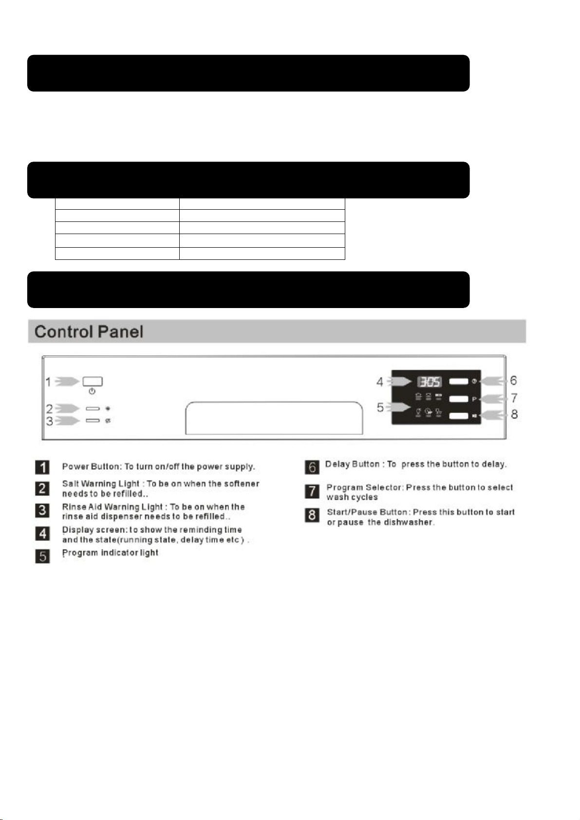
ControlPanelFeatures.........................................................................................................................................3
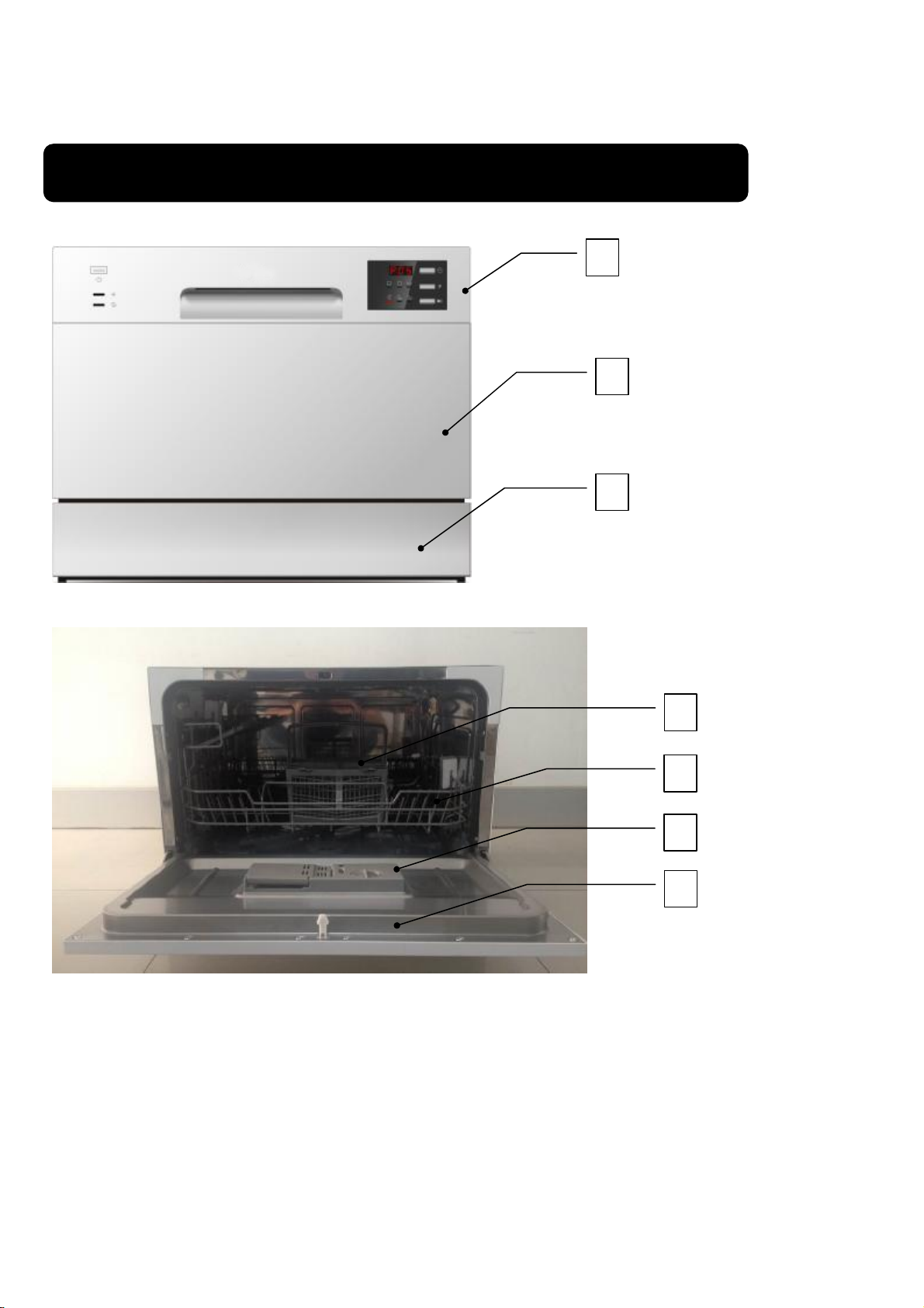
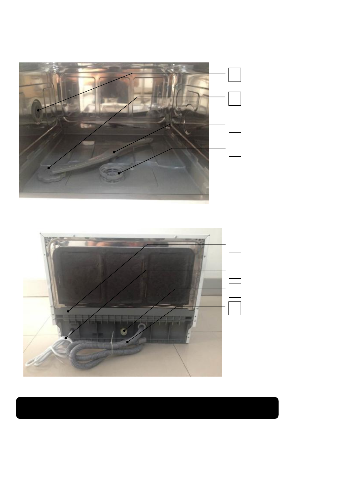
Component Locator Views...................................................................................................................................4
Dishwasher Components.....................................................................................................................................5
Maincontrolboard.........................................................................................................................................6
Floater assembly...........................................................................................................................................7
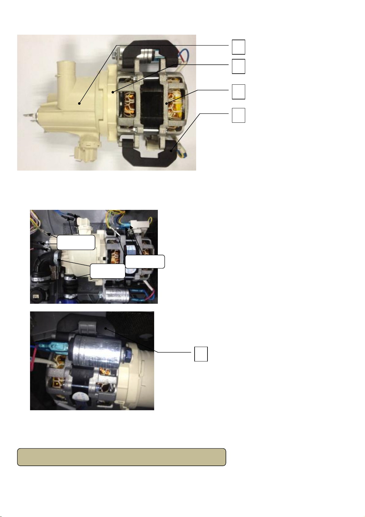
Heating pumpmotor assembly....................................................................................................................7
Heating pumpassembly...............................................................................................................................8
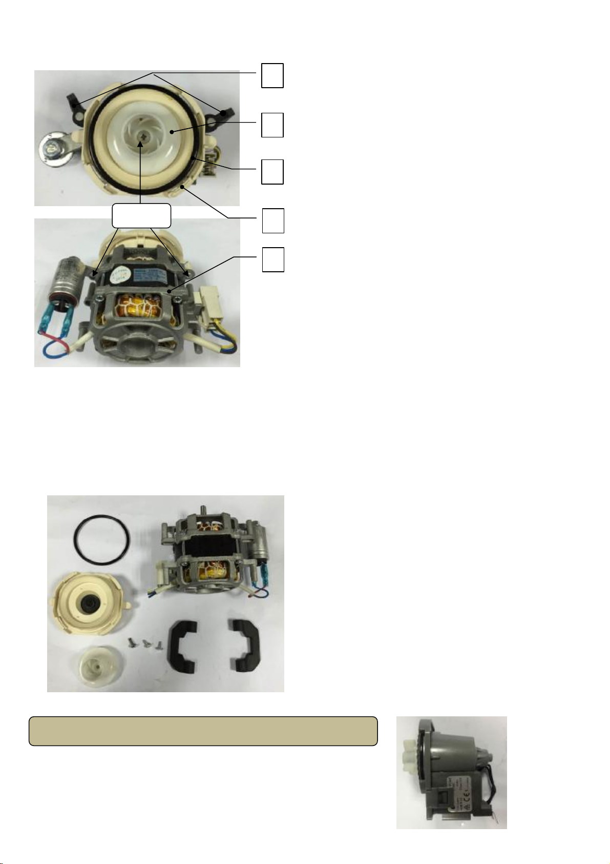
Motor assembly..............................................................................................................................................9
Drainpumpassembly.................................................................................................................................10
Checkplate...................................................................................................................................................11
Inlet valve......................................................................................................................................................11
Controlpanel................................................................................................................................................12

2
Operatingboard...........................................................................................................................................13
Outer Door....................................................................................................................................................13
Dispenser......................................................................................................................................................14
Inner Door.....................................................................................................................................................14
Shell...............................................................................................................................................................15
Doorlockassembly.....................................................................................................................................16
Air breaker....................................................................................................................................................16
Hinge assemblyand springsystem..........................................................................................................17
Tankassembly.............................................................................................................................................18
Troubleshooting.....................................................................................................................................................19

3
WQP6-3602 compactelectricaldishwasherwith6washing cyclesoffersgood washing
performancetosatisfyeverywashing requirement. Itselectroniccontroliseasyand convenientto
operate.The rackcanholdup to6setsofdishes.The size(width*depth*height: 550mm*
500mm*438mm)can easilyfitinanycornerofthe kitchen,and itsrecommendedtolocateat
which the water hose connectionisaccessible.
Rated voltage: 220~240V/ 50Hz
Rated power: 1170-1380W
Water pressure: 0.04~1.0MPa
Water temperature: maximum60
Capacity: 6settings
Note:all modelshave differentcontrolpanelfeatures and appearances.Alldetailcan be
referred touser manualsof the model.
Control Panel Features
Specification
Introduction

4
FrontView
Part N
ame:
1
control panel2
outerdoor
3
kick board
InteriorView(with basket)
Part Name:1
cutlerybasket
2
basket
3
dispenser
4
innerdoor
Component LocatorViews
2
1
2
3
4
3
1

5
InteriorView(With BasketRemoved)
Part Name:1
N
ut of air
breaker
2
WaterSoftenercover
3
Sprayer
4 FilterSystem
BackView
Part Name:1
Bottomboard
2
Powercord
3
Inlet hoseconnecter
4 Outerdrainhose
Note:Throughout thismanual, features and appearance may varyfromyour model.
WARNING: Always turnoffthe electricpowersupplybeforeservicing any electricalcomponent,
DishwasherComponents
1
2
3
1
2
3
4
4

6
making ohmmeter checks,or replacing any parts.
Note: Allvoltagechecksshouldbe made withavoltmeterhaving afull scalerange of250volts
orhigher.Afterservice iscompleted,be sureall safetygrounding circuitsarecomplete,
all electricalconnectionsaresecure, andallaccess panelsareinplace.
The maincontrolboardcontrolsallelectricalelementsinthe dishwashermachine.It located in
the protecting boxinthe bottomofdishwashermachine.And iteasyisreplaced when itcannot
work.
Removal and Replacement
1.Disconnect power supply.
2.Takeoff cutlerybasket, basket and filtersystem.
3.Turnthe dishwasher machine.And unfixallsnapsfor fixingcover ofbottomboard
.
Part Name:1
coverof
bottomboard
4.Pull outall housings and terminals(includingsomelockingterminals), thenunfixallsnaps
for fixing maincontrolboard.
Part name:1 protecting box2 maincontrol board
Note: markall housings and terminals positionsand colorsbeforepulling out them.
Note: someterminalsarelocking terminals.
Maincontrol boa
rd
1
1
2
snap
s

7
5.Reverse the aboveproceduretoinstall.And checkout all connectorsconnectswell.
Part Name:1
coverof bottomboard
2
microswitch
3 floaterholder4 floater
Removal and Replacement
1. Remove coverof bottomboard. (see maincontrol board removaland replacement)
2.Pull out all terminalsofmicroswitch.
3.Unfit snapsfixing microswitch tofloater holder.
4.Unfit snapsfixing floater holder tocover ofbottomboard.
5.Reverse the aboveproceduretoinstall.And checkout all connectorsconnected well.
F
loaterassembly
Heating pumpmotor
assembly
2
1
3
4
Terminlals
S
naps
S
naps

8
Part Name:1
heatingpumpassembly
2
lowerpumpcover
3 motorassembly4 motorhunger
Removal and Replacement
1.Remove coverof bottomboard. (see maincontrol board removaland replacement)
2.Pull out all terminalsofheating pumpmotor assembly.
Part Name:1 motorhunger
3.Removeclampsfixing heating pumpmotor assemblytosumpofbottomboard.
4.Unfitmotor hungersfixing heating pumpmotor assemblytobottomboard.
5.Reverse the aboveproceduretoinstall.And checkout all connectorsconnected well.
Heating pump
assembly
2
1
3
4
Clamps
Terminals
Terminal
s
1

9
Part Name:1
upperpumpcover
2
heatingelement
3 pressureswitchassembly
Removal and Replacement
1.Takeoutheatingpumpmotorassemblyfromthe dishwashermachine. (see mainheating
pumpmotorassembly removalandreplacement)
2.Unfit snap ofheating pumpassembly, and contrarotateheating pumpassembly.
3.Reverse the aboveproceduretoinstall.And checkout all connectorsconnected well.
Motor
assembly
2
1
3
S
nap

10
Part Name:1
motorhunger
2
impellerassembly3
pumpseal ring
4 lowerpump5 motorassembly
Removal and Replacement
1.Takeoutheating pumpmotorassemblyfromthe dishwashermachine. (see mainheating
pumpmotorassembly removalandreplacement)
2. Disassembleheating pumpmotorassembly.(see heatingpumpassembly removaland
replacement)
3.Takeouttwomotorhungers,and removescrewsforfixing impellerassemblyand lower
pumptomotor assembly.
4.Reverse the aboveproceduretoinstall.And checkout all connectorsconnected well.
Removal and Replacement
1.Remove coverofbottomboard. (see maincontrolboard removal
and replacement)
Drainpump
assembly
2
1
3
5
Screws 4

11
2.Pull out all terminalsofdrainpumpassembly.
3.Unfit snap ofdrainpumpassembly, and contrarotatedrainpumpassemblytotake it out.
4.Reverse the aboveproceduretoinstall.And checkout all connectorsconnected well.
Removal and replacement
1.Remove coverofbottomboard. (see maincontrolboard removaland
replacement)
2.Removeclamp fixinginnerdrainhose to bottomboard, and pullit out .
Part Name:1 innerdrainhose2 check plateassembly
3.Pull out checkplatefromcheckplateholder, and replaceanew checkplate.
4.Reverse the aboveproceduretoinstall.And checkout all connectorsconnectswell.
Removal and Replacement
1.Remove coverof bottomboard. (see maincontrol board removaland replacement)
2.Pull out all terminalsofinlet valve.
Check plate
Inletvalve
Terminals
S
nap
1
2

12
3.Removeclampforfixingconnectinghose toinletvalve,and contrarotateinletvalvetotake it
out.
4.Reverse the aboveproceduretoinstall.And checkout all connectorsconnected well.
The outer door coversthedoor tothe dishwasher and protectsthe detergent dispenser.
Removal and Installation
1.Open the door ofdishwasher.And removeallscrewsfor fixing controlpanel.
2.Removescrew and unfixall snapsfor fixing the operating board.
Part Name:1
Control panel
2
operating board
3.Reverse the aboveproceduretoinstall.And checkout all connectorsconnected well.
Control Panel
1
2
Screw
snaps snaps
Clamps Terminals
Screws
Screw

13
Removal and Replacement
1.Disconnect power supply.
2.Removeall screwsforfixing controlpanel. (see control panel removaland installation)
3.Put out allhousings for connecting operating board.
4.Removescrewandunfixallsnapsforfixing theoperating board. (see controlpanel
removaland installation)
5.Reverse the aboveproceduretoinstall.And checkout all connectorsconnected well.
The outer door coversthedoor tothe dishwasher and protectsthe detergent dispenser.
Removal and Installation
1.Open the door ofdishwasher.And removeallscrewsfor fixing outer door.
2.Reverse the aboveproceduretoinstall.And checkout all connectorsconnected well.
FrontView(withouterdoorassemblyremoved)
Part Name:
1
streamresistant cotton 2
d
ispenser
3
so
undabsorbing
cotton4 doorhinge(left) 5 rod fordoorhinges 6 doorhinge
(right) 7 kick board
Operatingboard
OuterDoor
5
1
2
3
4
6
7
Screws

14
The dispenserautomaticallydispenses boththe detergentand the rinse agentatthe appropriate
times.The dispenser isactivated twice during awashcycle.
The firsttime,the dispenserisactivated, thelever slides up theright-hand pathof the
connecting rod.Thisaction moves thecovercatch andreleases the detergentcover.When
deactivated,the leverresetstorestunderthe notch inthe centerof theconnecting rod.When
activated forthe secondtimeinacycle,the leverlifts theconnectingrod bythe notch,lifting
the rinsedispenser plunger and releasing therinseagent. When deactivated,the leverreturns
toitsoriginalstarting position. Themagneticsensor isconnected torinseaidwarning lightat
controlpanelbywires.When the indicator lightsup,it shouldadd morerinseaid.
Part Name:1
covercatch
2
detergent powercompa
rtment
3 cover4 sight glass5 rinse agent cap
6 detergent tablet compartment
Part Name:1
electromagneticvalve2
lever
3 plunger4 connecting rod
5 magneticsensor
Removal and Replacement
1.Removeouter door assembly. (see outerdoor removaland installation)
2.Pull out all terminalsofdispenser.Then removeallscrewsfor fixing dispenser.
Part Name:1
dispenserbrackets
2
dispenser
3.Reverse the aboveproceduretoinstall.And checkout all connectorsconnected well.
Caution: Inner door of edges aresharp.
InnerDoor
Dispenser
5
1
2
3
4
6
4
1
2
3
5
t
erminal
s
2
1
Screws

15
Removal and Replacement
1.Removeouter door assembly. (see outerdoor removaland installation)
2. Removecontrolpanel.(see control panel removaland installation)
3. Removedispenser. (see dispenser removaland replacement)
4.Removeall screwsforfixing inner door toright hingeassemblyand left hinge assembly.
5.Removedispenser. (see dispenser removaland replacement)
6.Reverse the aboveproceduretoinstall.And checkout all connectorsconnected well.
Removal and Installation
1.Removeall screwsforfixing shell withtankand bottomboardassemblyinthe rearof
dishwasher machine.
2.Pushthe shell fromfront toback.Andtakeit awayfromthe machine.
3.Reverse the aboveproceduretoinstall.And checkout all connectorsconnectswell.
Top View(with shellremoved)
Shell
Screws
Screws

16
Part Name:1
doorswitchassembly
2
absorber
3
4
backboard
Removal and Replacement
1.Disconnect power supply.
2.Removeshell. (see shell removaland installation)
3.Unfit snap ofdoorlockassembly, and pushit out.
4.Pull out all terminalsofmicroswitch fixed onthe door lockassembly.
5.Reverse the aboveproceduretoinstall.And checkout all connectorsconnected well.
Removal and Replacement
1.Remove shell. (see shell removaland installation)
2.Takeout absorbingcotton, upperbasket and lowerbasket.
3.Contrarotatenut ofair breaker and take out it.
4.Pull out terminalofair breaker, and unfit snapsofair breaker fixing onsoftener.
DoorLock Assembly
A
ir
breaker
1
2
3
4
S
nap
L
ocking t
erminals
clamps

17
5.Turnthedishwasher machine,removethe coverofbottomboard.(see maincontrolboard
removaland installation)
6.Removeall clampsfor fixing connecting hoses toair breaker.
7.Reverse the aboveproceduretoinstall.And checkout all connectorsconnected well.
Part Name:1 spring holder2 spring3 friction strip4 absorbing cotton
5 hingeassembly
Removal and Replacement
1.Remove shell. (see shell removaland installation)
2.Takeout absorbingcotton.
3.Takeoff spring holder fromthe slot ofbottomboard.
Caution: Thisoperationmust be morecarefully, it iseasy tobe injured by thefriction strip.
Hingeassemblyand Spring system
snap
1
2
3
4
5

18
4. Remove all screwsfor fixing hinge assemblytobottomboard.
5.Reverse the aboveproceduretoinstall.And checkout all connectorsconnected well.
Removal and Installation
1.Remove shell. (see shell removaland installation)
2.Takeout absorbingcotton.
3.Removeair breaker. (see airbreaker removalandreplacement)
4.Removeall screwsforfixing tankassemblytobottomboard.
5.Reverse the aboveproceduretoinstall.And checkout all connectorsconnected well.
Tankassembly
Screws
Screws

19
SYMPTOM CHECKFORTHEFOLLOWING REMEDY
Error:E1
(Dishwasher
will notfill with
waterorwill not
fill properly.)
The water supplyisturnedoff. Turnthe water supplyon.
Defectivewater fillvalve. Replace the water fillvalve.
Low water pressure. Minimumwater pressureof20 PSI.
Obstructed water fillsvalveor hose. Disassembleandclean the waterfill valveand
hose.
Damagedor defectivewiring. Repair the wiring.
Defectivepressureswitch forhigh water
levelsafeguard. Replace the pressureswitch.
Defectiveflowmeter. Replace the flowmeter
Heavy water usage elsewhereinhome. Use dishwasherwhen waterusageisata
minimum.
DefectivePCBassembly Replace the PCBassembly
Dishwasher will
not
pumpout.
Defectivedrainpump. Replace the drainpump.
Obstructed drainhose checkthe drainhose
DefectivePCB assembly Replace the PCBassembly
Damagedor defectivewiring. Repair the wiring.
Dishwasherruns
but. will not heat.
Low input voltage. The lowest input voltage is198V
DefectiveThermalresistor Replace the Thermalresistor
Damagedor defectivewiring. Repair the wiring.
Too littlewater fill. See “Too littlewater fill.”
Defectivemicro-switchofpressure
switch assembly. Replace the micro-switch ofpressureswitch
assembly.
Defectiveheatingelement. Replace the heatingelement.
DefectivePCB assembly Replace the PCBassembly
Error : E4
(overfall alarm)
Defectivemicro-switchforoverfall
safeguard Replace the micro-switch
Damagedor defectivewiring. Repair the wiring.
DefectivePCB assembly Replace the PCBassembly
Water leaksfromdishwasher. See “Water leaks fromdishwasher”
Donotwork
when pressstart The door not close well closethe door
Defectivedoor switch contacts. Replace the door switch.
Defectivedoor handleassembly. Replace the door handleassembly.
Damagedor defectivewiring. Repair the wiring.
DefectivePCB assembly Replace the PCBassembly
Too littlewater
fill. Dishwasher not level. Levelthe dishwasher.
Defectiveflowmeter. Replace the air breaker
Clogged filter assembly. Clean the filter assembly.
Water siphonsout Clean orReplace the air breaker
Dishwasherruns
withdoor open. Defectivedoor switch contacts. Replace the door switch.
Defectivedoor lockassembly. Replace the door lockassembly.
Damagedor defectivewiring. Repair the wiring.
DefectivePCB assembly Replace the PCBassembly
Motor humsbut
will not start or
run.
Defectivemotor bearings. Replace the motor.
Defectivemotor capacitor. Replace the motor capacitor.
Damagedor defectivewiring. Repair the wiring.
Impropermotor voltage.Replace the motor.
Motortrips outon
internalthermal
overload
Motor windingsshorted.Replace the motor.
Impropermotor voltage. Replace the motor.
Defectivemotor capacitor. Replace the motor capacitor.
Troubleshooting
Error:E3

20
protector Defectivemotor bearings. Replace the motor.
Repeated
dishwasher
cycles.DefectivePCB assembly Replace the PCBassembly
Waterremains in
bottom Asmallamountofwater(insumparea)
isnormal.
Thisisnecessarytokeepthe pumpprimed and is
drained automaticallyatthe beginning ofeach
cycle.
Defectivedrainpump Replace the drainpump.
DefectiveCheckplate Clean orReplace the Checkplate
DefectiveOne wayvalve Clean orReplace the air breaker
Spotting or
filming on
glasses
(reposition of
foodsoil).
Detergentallowed tostand too long in
the dispenserorexcessiveamountsof
detergent arebeing used.Instructthe customeron properuse ofdishwasher
detergent. Refer tothe owner smanual.
Improper loading ofdishes, pots,
pans, andnesting ofsilverware.
Noisypump
assembly.
Debrisinbottomoftub sumparea. Clean out the sumparea.
Pumppartswerenot properlyinstalled. Inspectthe pumpandcorrectand installation
errors.
Impellersarenotproperlyshimmedor
arerubbing.
Use theshimguage furnished inthe impellerseal
kit. When thesealisproperlyshimmedthe
impellerswillbe inthe correct operating position.
Poor washability.
Clogged filter assembly. Clean the filter assembly.
Dishwarestopthe sprayer revolvethe sprayer beforewash.
Improperloading ofdishes,pots,pans,
and nestingofsilverware. Refer tothe ownersmanual.
Littledetergent/rinse module
Selectimproperprogram
Defectivedetergent/rinse moduleReplace the etergent/rinsemodule.
Defectivesprayarm. Checksprayarmfor proper rotation.
Too littlewater fill. See “Too littlewater fill”symptom.
Defectivemotor pump Replace the motor pump
Poordrying of
dishes Improperloading ofdishes,pots,pans,
and nestingofsilverware. Instructthe customeronproperloading ofthe
dishwasher. Refer tothe ownersmanual.
Selectimproperprogram
Defectivedispenser Replace the dispenser
Water leaksfrom
dishwasher.
Too much water fill. See previous symptom.
Defectivedrainpump Replace the drainpump
Dishwasher not level. Levelthe dishwasher.
Soapsuds leakfromdishwasher. Refer touse and caremanual.
Loosehoseclamps. Tighten or replacehoseclamps.
Looseoverflow cover. Remount the overflow cover.
Drainpumpassemblynotseated
properlywithsump. Remount the drainpumpassembly.
Defectiveflow systemseals. Replace the flow systemseals.
Table of contents
Other Midea Dishwasher manuals

Midea
Midea MDWS-2703 User manual

Midea
Midea MDWMINIPLUS User manual

Midea
Midea MDWMINIW User manual

Midea
Midea WQP6-3206B How to use

Midea
Midea JHDWSD7SS User manual

Midea
Midea DWP63608 User manual

Midea
Midea MDW15KSS User manual

Midea
Midea MFD60S300W.2-ES User manual

Midea
Midea JHDW143BK User manual

Midea
Midea MDW15GSS User manual

Midea
Midea MDT24P4AST User manual

Midea
Midea MDW45FSS User manual

Midea
Midea WQP8-7636Q User manual

Midea
Midea MDWFS014LSO User manual

Midea
Midea WQP8-B9252 User manual

Midea
Midea WQP6-3208-US User manual

Midea
Midea CD400 User manual

Midea
Midea WQP6-3607 User manual

Midea
Midea WQP12-U7635R User manual

Midea
Midea MDP18B10AWWC User manual