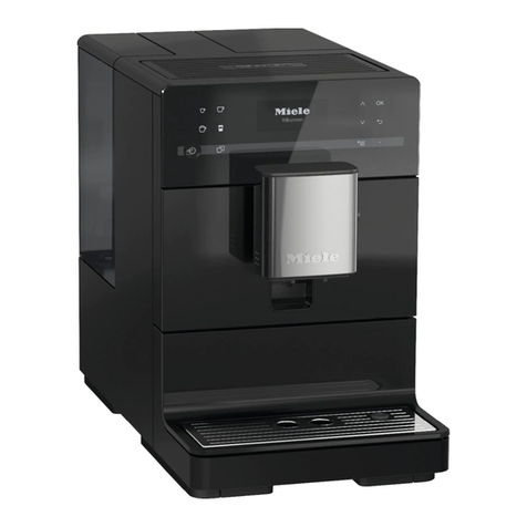
Miele CM6 Series Manual

TECHNICAL INFORMATION
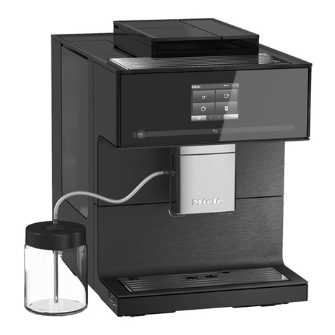
CM6 Countertop Coffee Systems
© 2018 Miele USA

Technical Information
2
CM6
Table of Contents
A Warning and Safety Instructions.......................................................................6
1General.................................................................................................................. 6
2Risk of Burning or Scalding................................................................................... 6
3Touch Current Measurement ................................................................................ 6
4Before the First Use .............................................................................................. 7
BModification History............................................................................................7
CTechnical Data.....................................................................................................7
DLayout of Electrical Components....................................................................10
1CM 61x0.............................................................................................................. 10
2CM 63x0.............................................................................................................. 11
001Overview ............................................................................................................12
2 Function............................................................................................................... 12
2.1Optical Interface ........................................................................................... 12
2.2Water Paths.................................................................................................. 12
2.2.1Overview..................................................................................................12
2.2.2Coffee ......................................................................................................13
2.2.3 Hot Water (CM 63x0 Only) ......................................................................14
2.2.4 Hot Milk....................................................................................................14
2.2.5Milk Froth.................................................................................................15
2.2.6 Rinse........................................................................................................15
2.3 Brew Unit Drive............................................................................................. 16
2.3.1 Microswitch Locations .............................................................................16
2.3.2 Brew Unit Presence Monitoring...............................................................16
2.3.3 Electronic Grind Amount Compensation .................................................16
2.3.4 Brew Unit Drive, Home Position ..............................................................18
2.3.5 Brew Unit Drive, Compressing Position (Brew Position).........................18
2.3.6 Brew Unit Drive, Drain Position ...............................................................19
2.4 Machine Response after Power Supply Failure............................................ 20
2.5Drip-Tray Sensing......................................................................................... 20
2.5.1Fill Level ..................................................................................................20
2.5.2Presence .................................................................................................20
3 Fault Repair......................................................................................................... 21
3.1F1 - Short Circuit in Heater NTC (R30-14).................................................... 21
3.2F2 - Open Circuit in Heater NTC (R30-14) ................................................... 22
3.3F10 - No Water Flow .................................................................................... 22
3.4F17 - Insufficient Water Flow........................................................................ 23
3.5F28 - Too Much Ground Coffee in Brew Unit................................................ 24
3.6F38 - Display/Control Electronic EPB (N1-2) and Power Electronic EPL
(1N1-1, 2N1-1) Not Compatible .................................................................... 24
3.7F40 - Power Electronic EPL Fault (1N1-1, 2N1-1)........................................ 25
3.8F41 - EEPROM Faulty/Data Fault ................................................................ 25
3.9F42 - Line Frequency Not Registered........................................................... 25
3.10F73 - Brew Unit Fault.................................................................................... 25
3.11F74 - Ceramic Valve (M29) Fault.................................................................. 26
3.12F76 - Brew Unit Compression Fault.............................................................. 27
3.13F77 - Ceramic Valve (M29) Initialization Fault .............................................. 27
3.14F80 - Heater (R1) Not Heating...................................................................... 27
3.15F82 - Heater (R1) Too Hot............................................................................ 28

Technical Information
3
CM6
3.16 F235 - Display/Control Electronic (N1-2) Communication Fault ................... 29
3.17“50 Portions until Descale” Message ............................................................ 29
3.18“Empty Drip Tray” Message, But Drip Tray Isn't Full..................................... 29
3.19Drip Tray Must Be Emptied Frequently......................................................... 29
3.20Coffee or Espresso Too Cold ....................................................................... 30
3.21 Milk Froth Unsatisfactory or Sputtering......................................................... 30
3.22No or Very Little Coffee Flowing from Spout................................................. 30
3.23Coffee Tastes Too Bitter............................................................................... 30
3.24Coffee Grounds Next to the Brew Unit ......................................................... 31
3.25Water Pump Does Not Pump ....................................................................... 32
4 Service ................................................................................................................ 32
4.1Drink Settings (Customer Programming)...................................................... 32
4.2 Machine Settings (Customer Programming)................................................. 33
4.3Service Programming ................................................................................... 37
4.4Service Mode................................................................................................ 38
4.5Top Cover Removal...................................................................................... 41
4.6 Side Casing Removal ................................................................................... 43
4.7 Cup Warmer (R39) Removal (CM 63x0 Only) .............................................. 44
4.8 Front Panel Removal.................................................................................... 45
4.9 EPB Display/Control Electronic (N1-2) Removal .......................................... 45
4.10 Door Contact Switch (S24) Removal ............................................................ 46
4.11 Grinder (M25) Removal ................................................................................ 48
4.12Grinder Thermostat (F3-3) Removal............................................................. 51
4.13 EPL Power Electronic (1N1-1, 2N1-1) Removal........................................... 51
4.14Chute Present Switch (S87-5) Removal ....................................................... 52
4.15 Pump (M7) with Thermostat (F3-2) Removal................................................ 52
4.16 Flow Meter (B3-4) Removal.......................................................................... 53
4.17 Water Tank Sensor (B3-18) Removal........................................................... 53
4.18Drip Tray Present Switch (S87-1) Removal.................................................. 53
4.19Ceramic Valve (M29) Removal..................................................................... 54
4.20 Heater (R1)/Fuse (1F8, 2F8)/NTC (R30-14) Removal.................................. 55
4.21 Removing the Brew Unit Drive (M26) and Brew Unit Switches..................... 56
4.22 Brew Unit Present Switch (S87-2) Removal ................................................. 59
4.23Grind Amount Step Contact Switch (S51-4) Removal .................................. 59
4.24Dispenser Assembly, Spout Present Switch (S87-6) Removal..................... 59
4.25Hot-Water Spout Removal............................................................................ 61
Technical Service Bulletins..........................................................................................63
1CM 6X; F80 Cause and Repair ........................................................................... 63
List of Figures
Figure C-1: CM 61x0......................................................................................................... 7
Figure C-2: CM 63x0......................................................................................................... 8
Figure D-1: CM 61x0 Component Layout ....................................................................... 10
Figure D-2: CM 63x0 Component Layout ....................................................................... 11
Figure 001-1: Optical Interface Location......................................................................... 12
Figure 001-2: Water Path Overview................................................................................ 12
Figure 001-3: Water Path for Coffee............................................................................... 13
Figure 001-4: Water Path for Hot Water (CM 63x0)........................................................ 14
Figure 001-5: Hot Milk..................................................................................................... 14
Figure 001-6: Milk Froth.................................................................................................. 15

Technical Information
4
CM6
Figure 001-7: Rinse......................................................................................................... 15
Figure 001-8: Brew Unit Drive Switches ......................................................................... 16
Figure 001-9: Actuator and Compensation Microswitch ................................................. 17
Figure 001-10: Measurable Volume Areas ..................................................................... 17
Figure 001-11: Selectable Volume Areas ....................................................................... 17
Figure 001-12: Home Position, Rear View...................................................................... 18
Figure 001-13: Home Position, Front View ..................................................................... 18
Figure 001-14: Brew Position, Rear View ....................................................................... 19
Figure 001-15: Brew Position, Front View....................................................................... 19
Figure 001-16: Drain Position, Rear View....................................................................... 20
Figure 001-17: Front View............................................................................................... 20
Figure 001-18: Drip Tray Present Switch........................................................................ 21
Figure 001-19: Pressure Pump....................................................................................... 23
Figure 001-20: Brew Unit Switches................................................................................. 26
Figure 001-21: Grind Amount Compensation Switch...................................................... 31
Figure 001-22: Top Cover Screw, Water Tank Side ....................................................... 42
Figure 001-23: Top Cover Screws, Brew Unit Side ........................................................ 42
Figure 001-24: Top Cover Retainers............................................................................... 43
Figure 001-25: Front Casing Screws .............................................................................. 43
Figure 001-26: Screw Cover ........................................................................................... 44
Figure 001-27: Side Casing Screws at Rear of Appliance.............................................. 44
Figure 001-28: Cup Warmer Screws............................................................................... 45
Figure 001-29: Front Panel Screws ................................................................................ 45
Figure 001-30: Display/Control Electronic Cover Retainers............................................ 46
Figure 001-31: Display/Control Electronic Wiring Harness............................................. 46
Figure 001-32: Grinder Cover and Power Electronic Screws ......................................... 47
Figure 001-33: Grinder Cover Screw .............................................................................. 47
Figure 001-34: Door Contact Switch............................................................................... 48
Figure 001-35: Beans Container Screws ........................................................................ 49
Figure 001-36: Ground Coffee Chute Screws................................................................. 49
Figure 001-37: Grinder Screws and Ground Coffee Chute Base Screw......................... 50
Figure 001-38: Grinder Thermostat................................................................................. 50
Figure 001-39: Grinder Thermostat Connection ............................................................. 51
Figure 001-40: Power Electronic Screw.......................................................................... 52
Figure 001-41: Chute Present Switch ............................................................................. 52
Figure 001-42: Pump Connections ................................................................................. 53
Figure 001-43: Water Tank Sensor and Drip Tray Present Switch................................. 54
Figure 001-44: Ceramic Valve Screw ............................................................................. 55
Figure 001-45: Heater Assembly .................................................................................... 56
Figure 001-46: Brew Unit Drive Screws.......................................................................... 57
Figure 001-47: Pump/Flow Meter Mounting-Bracket Screw ........................................... 57
Figure 001-48: Water Tank Sensor/Drip Tray Present Switch Mounting-Bracket Screw 58
Figure 001-49: Brew Unit Drive Cover ............................................................................ 58
Figure 001-50: Brew Unit Drive Position Switches.......................................................... 59
Figure 001-51: Hose Cover Screws................................................................................ 60
Figure 001-52: Dispenser Assembly Hoses and Screws; Spout Present Switch............ 60
Figure 001-53: Front Trim Piece Screws ........................................................................ 61
Figure 001-54: Hot-Water Spout Removal...................................................................... 62
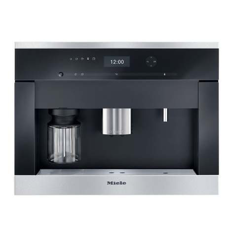
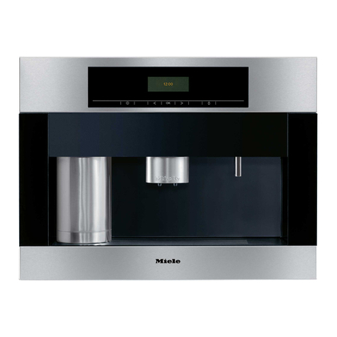
Technical Information
5
CM6
List of Tables
Table C-1: Serial Modifications ......................................................................................... 8
Table C-2: Technical Data ................................................................................................ 9
Table C-3: Quantities until Obligatory Descaling .............................................................. 9
Table C-4: Technical Data ................................................................................................ 9
Table 001-1: Switch Cam Settings.................................................................................. 17
Table 001-2: Drink Settings (Customer Programming) ................................................... 33
Table 001-3: Machine Settings (Customer Programming).............................................. 36
Table 001-4: Service Programming ................................................................................ 38
Table 001-5: Service Mode............................................................................................. 41
Table 001-6: Brew Unit Position Switches ...................................................................... 41

Technical Information
6
CM6
A Warning and Safety Instructions
1 General
Any repairs or maintenance performed by unqualified personnel could be
dangerous. All applicable laws, codes, regulations, and accident prevention
guidelines must be observed when serving, modifying, testing or maintaining
appliances. All repairs should be performed by a trained technician in strict
accordance with local, state and national codes.
Before any service work is started, the machine must be safely disconnected
from its power source. Even with the machine switched off, voltage may exist
on some components.
After work has been completed, as a matter of standard practice, a visual as
well as an operational check should be performed.
Note:
Before starting any service or repair work, remove all containers and the drip
tray with the spill guard grid from the appliance. Also empty the beans
container, lay the appliance on its right side and transfer any remaining
beans to an appropriate container.
2 Risk of Burning or Scalding
Some components may be very hot, such as heaters. Also, some
components may contain pressurized steam. Use caution when working on
these parts.
To protect from burns:
1. Allow the appliance to cool down for approximately one hour before
starting service or repair work, so that the heaters can cool.
2. In service mode, pump cool water through the heater for a few minutes to
shorten the cooling time. Use the component test for the pump. See
Table 001-5.
3 Touch Current Measurement
Touch current measurement should be carried out on all accessible
conductive parts that are not connected to ground.
Warning!
Touch current measurement may only be performed after the ground
connection of the appliance under test has been checked and found to be
satisfactory!
A defective appliance, as well as accessible conductive parts that are not
connected to ground, may carry dangerous voltages!

Technical Information
7
CM6
4 Before the First Use
Clean the appliance and remove any protective foils before the first use.
See the operating manual.
Plug in the appliance. If the power cord is too long, it can be pushed into
the hole in the back of the appliance.
Fill the beans container. See the operating manual.
Fill the water tank with fresh, cold tap water. See the operating manual.
B Modification History
When? Who? What?
3/7/2018 Jessica Naples Tech service bulletin added
6/21/2017 Jessica Naples Model numbers updated
9/28/2016 Jessica Naples Minor changes throughout
6/25/2014 Jessica Naples Conversion for Website
5/14/2014 Sabine Hötte Version 4
1/15/2014 Sabine Hötte Version 3
12/4/2013 Sabine Hötte Version 2
10/16/2013 Sabine Hötte Version 1
C Technical Data
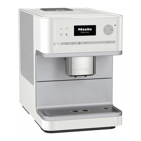
Figure C-1: CM 61x0

Technical Information
8
CM6
Figure C-2: CM 63x0
Production index Modification Effective
ID no. Machine no. Date
EPB EPL
10 Series start 3059_V2 3058_V2 97276816 10/25/2013
Table C-1: Serial Modifications
Model CM 61x0 CM 63x0
Construction Countertop with bean system
Design Display with DirectSensor
Dimensions
Height 14.1”
Width 9.9”
Depth 16.8”
Features
Individual language selection Yes Yes
Time-of-day display No No
Date display No No
CupSensor No No
Infinitely variable height-adjustable
serving spout 8 - 14 cm 8 - 14 cm
Cup warmer No Yes
BrilliantLight No Yes
Signal tones No Yes

Technical Information
9
CM6
Model CM 61x0 CM 63x0
Capacity
Water tank 1.8L (61 fl.oz.)
Beans container 300g (10.6 oz.)
Waste container 10 pucks
Electrical connection
Output power max. 1.45kW max. 1.45kW (incl. cup
warmer)
Fuse rating 10A
Voltage 120VAC
Frequency 60Hz
Power cord 4.5’
Drink temperatures
1
Espresso 185°F ± 5°F
Coffee 185°F ± 5°F
Milk froth 122°F (± 5°F)
Hot milk 122°F (± 5°F)
Hot water (CM 63x0 only) 185 - 203 °F
Table C-2: Technical Data
1 Measure the temperature half an inch (1 centimeter) below the dispenser, not in the cup.
Water hardness settings Water flow settings Quantities (approx.) until display shows
"No. until descaling: 50"
Steam [minutes] Coffee [liters]
Soft Normal or half, no
effect
90 80
Medium 60 60
Hard 30 40
Very hard Normal 20 20
Half 10 10
Table C-3: Quantities until Obligatory Descaling
Grinder (M25)
Voltage 120V
Grinder thermostat 3F3 trips at 194°F (90°C)
Brew unit drive (M26)
Voltage 0 - 12 V pulse-width-modulated
Flow-through heater (R1)
Voltage 120VAC
Power 1450W
NTC (R30-14) 25°C 100°C 160°C
100kΩ5.5kΩ1kΩ
2 fuses (1F8, 2F8) 378°F (192°C)
Pump (M7)
Construction Piston
Voltage 120V
Power 60W
Thermostat (F3-2) 221°F
Flow meter (B3-4)
Pulses per revolution 2
Table C-4: Technical Data

Technical Information
10
CM6
D Layout of Electrical Components
1 CM 61x0
Figure D-1: CM 61x0 Component Layout
1EPL power electronic (1N1-1, 2N1-1) 10Pump (M7) with thermostat (F3-2) 105°C
2Chute present switch (S87-5) 11Drip tray present switch (S87-1)
3Grinder (M25) 12Spout present switch (S87-6)
4Grinder thermostat (F3-3) 90°C 13Water tank sensor (B3-18)
5Brew unit present switch (S87-2) 14EPB display/control electronic (N1-2)
6Brew unit drive (M26) with 15Heater NTC (R30-14)
2 position switches (S60-1, S60-2) and 16Heater (R1)
grind amount step contact switch (S51-4) 17Ceramic valve (M29) with
7Flow meter (B3-4) position switch (S60-3) and
8On/off switch (S2) step contact switch (S51-1)
9Door contact switch (S24) 182 heater fuses (1F8, 2F8) 192°C

Technical Information
11
CM6
2 CM 63x0
Figure D-2: CM 63x0 Component Layout
1EPL power electronic (1N1-1, 2N1-1) 11Drip tray present switch (S87-1)
2Chute present switch (S87-5) 12Spout present switch (S87-6)
3Grinder (M25) 13Water tank sensor (B3-18)
4Grinder thermostat (F3-3) 90°C 14EPB display/control electronic (N1-2)
5Brew unit present switch (S87-2) 15Cup warmer (R39)
6Brew unit drive (M26) with 16Heater NTC (R30-14)
2 position switches (S60-1, S60-2) and 17Heater (R1)
grind amount step contact switch (S51-4) 18Ceramic valve (M29) with
7Flow meter (B3-4) position switch (S60-3) and
8On/off switch (S2) step contact switch (S51-1)
9Door contact switch (S24) 192 heater fuses (1F8, 2F8) 192°C
10Pump (M7) with thermostat (F3-2) 105°C

Technical Information
12
CM6
001 Overview
2 Function
2.1 Optical Interface
Figure 001-1: Optical Interface Location
The appliance has an optical interface for diagnostics and program updates. It can be
located with the “Find optical interface” function.
2.2 Water Paths
2.2.1 Overview
Figure 001-2: Water Path Overview
1 Pump (M7)

Technical Information
13
CM6
2 Flow meter (B3-4)
3 Water tank
4 Drain valve
5 Heater (R1)
6 Ceramic valve (M29)
Pos. 1 = Vacant
Pos. 2 = Ventilation, hot water
Pos. 3 = Hot water, steam, air
Pos. 4 = Steam, air open (milk froth)
Pos. 5 = Steam (hot milk)
Pos. 6 = Reference, closed
Pos. 7 = Coffee, decompression, rest
Pos. 8 = Rinse, air
7 Hot-water spout
8 Grinder (M25)
9 Brew unit
10 Coffee/milk spout
11 Milk container
12 Drip tray
2.2.2 Coffee
Figure 001-3: Water Path for Coffee
1 Pump (M7)
2 Flow meter (B3-4)
3 Water tank
4 Drain valve
5 Heater (R1)
6 Ceramic valve (M29) in pos. 7 = Coffee, decompression, rest
8 Grinder (M25)
9 Brew unit
10 Coffee/milk spout
12 Drip tray

Technical Information
14
CM6
2.2.3 Hot Water (CM 63x0 Only)
Figure 001-4: Water Path for Hot Water (CM 63x0)
1 Pump (M7)
2 Flow meter (B3-4)
3 Water tank
5 Heater (R1)
6 Ceramic valve (M29) in pos. 3 = Hot water, steam, air
7 Hot-water spout
12 Drip tray
2.2.4 Hot Milk
Figure 001-5: Hot Milk
1 Pump (M7)
2 Flow meter (B3-4)
3 Water tank
5 Heater (R1)
6 Ceramic valve (M29) in pos. 5 = Steam (hot milk)
10 Coffee/milk spout
11 Milk container
12 Drip tray

Technical Information
15
CM6
2.2.5 Milk Froth
Figure 001-6: Milk Froth
1 Pump (M7)
2 Flow meter (B3-4)
3 Water tank
5 Heater (R1)
6 Ceramic valve (M29) in pos. 4 = Steam, air open (milk froth)
10 Coffee/milk spout
11 Milk container
12 Drip tray
2.2.6 Rinse
Figure 001-7: Rinse
1 Pump (M7)
2 Flow meter (B3-4)
3 Water tank
5 Heater (R1)
6 Ceramic valve (M29) in pos. 8 = Rinse, air

Technical Information
16
CM6
10 Coffee/milk spout
12 Drip tray
2.3 Brew Unit Drive
2.3.1 Microswitch Locations
The brew unit is controlled via 4 microswitches (Figure 001-8).
After the brew unit has been activated, if one of the two positioning microswitches
(Figure 001-8, Item 3 or 4) has not switched within approximately 10 seconds, the
following fault is indicated: F73 – Brew Unit Fault (Section 001-3.10).
Figure 001-8: Brew Unit Drive Switches
2.3.2 Brew Unit Presence Monitoring
When the brew unit is correctly installed (i.e. inserted and locked into place), the brew
unit present monitoring microswitch is activated (Figure 001-8, Pos. 2).
2.3.3 Electronic Grind Amount Compensation
The grind amount compensation evens out variations in grinder settings and coffee
types.
The grind amount can be set in the customer programming mode for the various coffee
types, and corresponds to a specific grind time; see Table 001-2.
During the brewing process, the actuator on the brew unit drive passes over the pin on
the microswitch; see Figure 001-9. The further the actuator advances, the greater the
ground quantity in the brew unit.
1 Grind amount compensation microswitch (S51-4)
2Brew unit present monitoring microswitch (S87-2)
3Top positioning microswitch (“home” setting) (S60-1)
4Bottom positioning microswitch (“brew” setting) (S60-2)

Technical Information
17
CM6
Figure 001-9: Actuator and Compensation Microswitch
Five different settings can be registered:
Position Microswitch position Switching process
1 In front of the first cam Off
2 On the first cam Off, on
3 Between the two cams Off, on, off
4 On the second cam Off, on, off, on
5 Behind the second cam Off, on, off, on, off
Table 001-1: Switch Cam Settings
Three volume areas can be measured for the grind amount; see Figure 001-
10. They represent the selectable volume areas on the machine; see Figure
001-11.
Figure 001-10: Measurable Volume Areas
Figure 001-11: Selectable Volume Areas
If the measure quantity varies from the set quantity, then the grinding time will
be increased or decreased by approximately 0.2 seconds as appropriate
during the next grinding cycle. Because the maximum ground quantity
1Brew unit actuator
2Grind amount compensation microswitch
1, 2, 3 Measurable volume areas 1, 2 and 3
1, 2, 3 Selectable volume areas 1, 2 and 3

Technical Information
18
CM6
compensation is ± 1.6 seconds, this adjustment can be repeated up to 8
times.
2.3.4 Brew Unit Drive, Home Position
If the brew unit is in the home position, the left cam of the double-cam
element activates the top microswitch; the bottom microswitch is not switched
(Figure 001-12). The pawl is in the home position (Figure 001-13).
Figure 001-12: Home Position, Rear View
Figure 001-13: Home Position, Front View
2.3.5 Brew Unit Drive, Compressing Position (Brew Position)
The drive moves until the second cam of the double-cam element switches
the bottom microswitch, and the top microswitch is no longer switched (Figure
001-14). The pawl presses down on the spring (Figure 001-15) and closes
the drain valve. The ground coffee is slightly compressed and brewed.

Technical Information
19
CM6
Figure 001-14: Brew Position, Rear View
Figure 001-15: Brew Position, Front View
2.3.6 Brew Unit Drive, Drain Position
After the coffee is brewed, the drive moves back until the first cam of the
double-cam element activates the bottom microswitch and the top
microswitch is switched (Figure 001-16). The tension of the spring is
released, the drain valve is opened, and the residual water runs into the drip
tray before the coffee puck is dropped.

Technical Information
20
CM6
Figure 001-16: Drain Position, Rear View
Figure 001-17: Front View
2.4 Machine Response after Power Supply Failure
After a break in the power supply, the machine remains switched off (standby).
The fault memory and all settings carried out by the customer remain unchanged.
2.5 Drip-Tray Sensing
2.5.1 Fill Level
The amount of water flowing into the drip tray is registered by the flow meter. When a
certain amount is reached, the “Empty drip tray” message will be displayed.
The value for the water amount is saved when the appliance is switched off; emptying
the drip tray after shutoff will not change this value. See also Section 001-3.18.
2.5.2 Presence
The drip tray present switch (S87-1) detects when the drip tray is inserted.
Table of contents
Other Miele Coffee Maker manuals

Miele
Miele CVA 5068 Product manual

Miele
Miele CVA 2662 Specification sheet
Miele
Miele CVA 2662 User manual
Miele
Miele CM 6300 User manual

Miele
Miele cva 610 User manual

Miele
Miele CM 7750 User manual

Miele
Miele cva 610 Manual

Miele
Miele CVA 4070 EN-CA User manual

Miele
Miele CM 6160 User manual

Miele
Miele CM 6363 User manual

Miele
Miele CVA 2660 User manual

Miele
Miele CVA 744C User manual

Miele
Miele CVA 30xx User manual

Miele
Miele CVA 7775 User manual

Miele
Miele CVA 6431 User manual

Miele
Miele CVA 7775 User manual

Miele
Miele CM 6100 User manual

Miele
Miele CM 5000 User manual

Miele
Miele Built-in coffee machine User manual

Miele
Miele CVA 4075 EN-CA User manual