MIETHKE proGAV 2.0 User manual

CHRISTOPH MIETHKE GMBH & CO. KG
proGAV 2.0®
This Instructions for Use is NOT intended for United State users. Please discard.
The Instructions for Use for United States users can be obtained by visiting our website at www.aesculapusa.com
and clicking the "Products" menu. If you wish to obtain a paper copy of the Instructions for Use, you may request
one by contacting your local Aesculap representative or Aesculap's customer service at 1-800-282-9000.
A paper copy will be provided to you upon request at no additional cost.
0297
Gebrauchsanweisung | Instructions for use | Mode d’emploi
Instrucciones de manejo | Instruções de utilização
ES
GB FRDE
PT
US

INHALTSVERZEICHNIS
INDIKATION 4
TECHNISCHE BESCHREIBUNG 4
ARBEITSWEISE DES VENTILS 4
AUSWAHL DER GEEIGNETEN DRUCKSTUFE 5
DRUCKSTUFENERKENNUNG IM RÖNTGENBILD 6
ANWENDUNG DER INSTRUMENTE 7
EINSTELLUNG DER VERSTELLBAREN DIFFERENZDRUCKEINHEIT 9
MÖGLICHE SHUNTKOMPONENTEN 10
SCHLAUCHSYSTEME 10
IMPLANTATION 10
VENTILPRÜFUNG 11
DRUCK-FLOW-CHARAKTERISTIK 12
VORSICHTSMASSNAHMEN UND KONTRAINDIKATIONEN 13
FUNKTIONSSICHERHEIT UND VERTRÄGLICHKEIT MIT
DIAGNOSTISCHEN VERFAHREN 13
NEBEN- UND WECHSELWIRKUNGEN 13
STERILISATION 13
FORDERUNGEN DER MDD (RL 93/42/EWG) 13
MEDIZINPRODUKTEBERATER 14
VARIANTEN 14
45
| GEBRAUCHSANWEISUNG proGAV 2.0 GEBRAUCHSANWEISUNG |proGAV 2.0
DE DE
INDIKATION
Das proGAV 2.0 dient zur Liquordrainage bei
der Behandlung des Hydrocephalus.
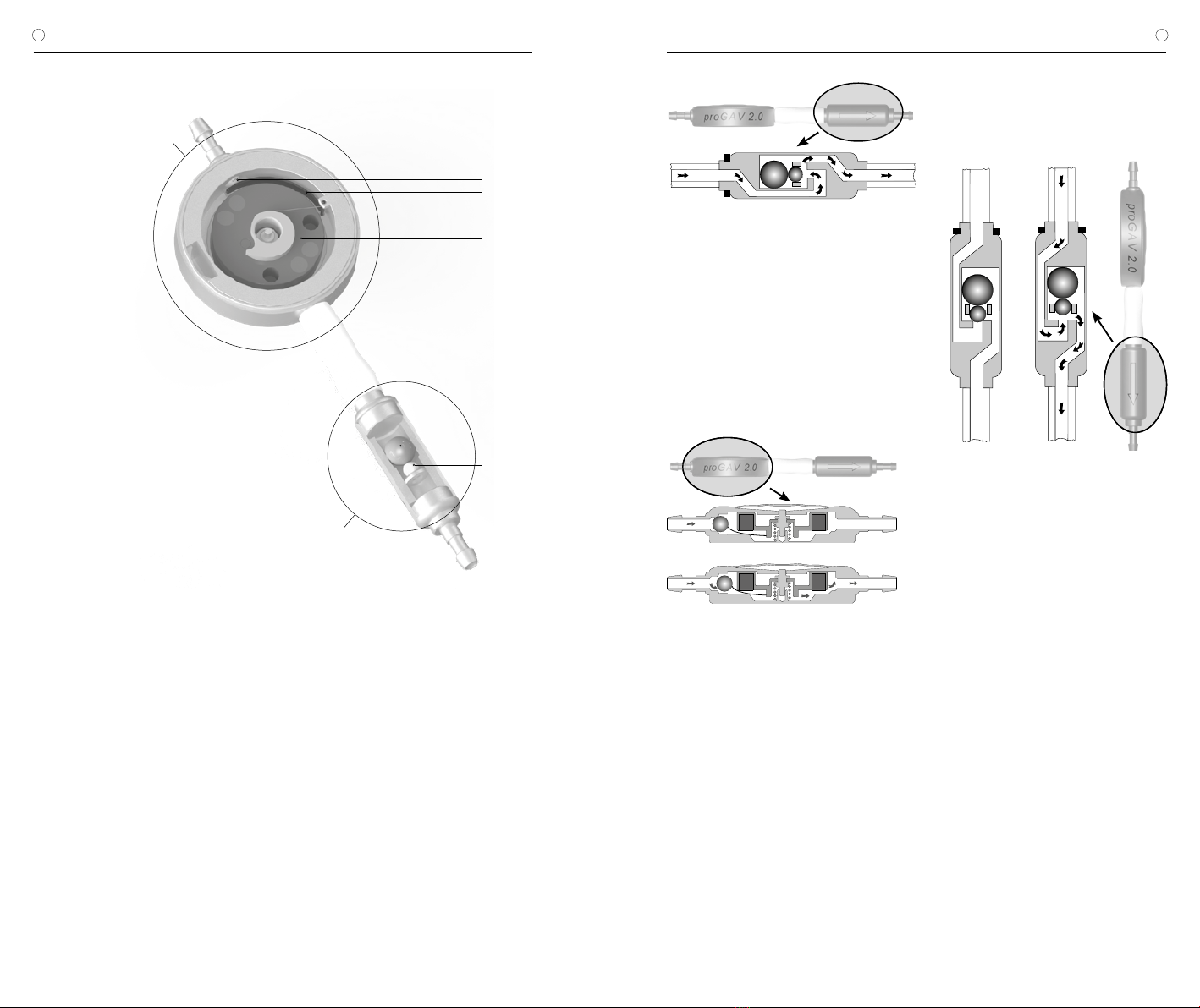
TECHNISCHE BESCHREIBUNG
Das proGAV 2.0 ist ein aus Titan gefertigtes
Ventil. Es besteht aus einer verstellbaren Diffe-
renzdruckeinheit und einer Gravitationseinheit
(Abb. 1).
Die verstellbare Differenzdruckeinheit besteht
aus einem stabilen Titangehäuse, in dessen
proximalem Teil ein bewährtes Kugel-Konus-
Ventil (1) integriert ist. Eine Stabfeder (2) be-
stimmt den Öffnungsdruck dieser Einheit. Über
einen drehbar gelagerten Rotor (3) kann die
Vorspannung der Feder und damit der Ventil-
öffnungsdruck durch die Haut verstellt werden.
Wesentliche Bestandteile der Gravitations-
einheit sind eine Tantalkugel (4), die den Öff-
nungsdruck, je nach Körperlage, dieses Ventils
bestimmt und eine Saphirkugel (5), die den prä-
zisen Verschluss garantiert.
ARBEITSWEISE DES VENTILS
Das proGAV 2.0 ist ein lageabhängig arbeiten-
des Hydrocephalusventil. Der Öffnungsdruck
des proGAV 2.0 setzt sich aus den Öffnungs-
drücken der verstellbaren Differenzdruckeinheit
und der Gravitationseinheit zusammen.
Horizontale Körperposition
Die Gravitationseinheit ist in der liegenden Kör-
perposition immer geöffnet und stellt keinen
Widerstand dar.
Abb. 2: Gravitationseinheit in horizontaler
Körperposition
Demnach ist der Öffnungsdruck des
proGAV 2.0 in der horizontalen Körperposi-
tion durch die verstellbare Differenzdruckeinheit
charakterisiert. Die prinzipielle Arbeitsweise der
verstellbaren Differenzdruckeinheit ist in Abb.
3a und b dargestellt. In Abb. 3a ist sie ge-
schlossen, sodass keine Drainage möglich ist.
In Abb. 3b ist die verstellbare Differenzdruckein-
heit im geöffneten Zustand abgebildet.
a)
b)
Abb. 3: Verstellbare Differenzdruckeinheit
in horizontaler Körperposition
a) geschlossen b) offen
Der intraventrikuläre Druck (IVP) des Patienten
ist erhöht und die Federkraft, die die Differenz-
druckeinheit sonst geschlossen hält, ist über-
wunden. Jetzt bewegt sich die Verschlusskugel
aus dem Konus und ein Spalt zur Liquordraina-
ge wird freigegeben.
Vertikale Körperposition
In dem Moment, in dem sich der Patient auf-
richtet, schließt die Gravitationseinheit (Abb.
4a). Der Öffnungsdruck des proGAV 2.0 wird
somit stark erhöht, denn nun muss zusätzlich
zum Öffnungsdruck der verstellbaren Differenz-
druckeinheit die Gewichtskraft der Tantalkugel
(Öffnungsdruck der Gravitationseinheit) über-
wunden werden. Erst wenn die Summe aus
IVP und und hydrostatischem Druck den Öff-
nungsdruck beider Einheiten übersteigt, ist eine
Drainage erneut möglich (Abb. 4b).
a) b)
Abb. 4: Gravitationseinheit in vertikaler Körperposition
a) geschlossen b) offen
Bei körperlicher Aktivität, die mit Erschütterung
einher geht - wie z.B. Joggen - kann sich der
Öffnungsdruck des proGAV 2.0 gemäß Labor-
ergebnissen temporär um 25% bis 35% ver-
ringern. Dies betrifft das Einzelventil wie auch
die Kombination mit einer Gravitationseinheit.
Grundsätzlich bleibt die Funktionalität erhalten.
Mit dem Ende der körperlichen Aktivität kehrt
der usprüngliche Öffnungsdruck stabil zurück.
AUSWAHL DER GEEIGNETEN
DRUCKSTUFE
Horizontale Körperposition
Der Öffnungsdruck für die horizontale Körper-
position wird durch die verstellbare Differenz-
druckeinheit errreicht. Die Druckstufe sollte hier
je nach Krankheitsbild und Indikation eingestellt
werden. Abhängig vom Krankheitsbild und Al-
ter des Patienten kann der Öffnungsdruck für
diese Körperposition zwischen den Druckstufen
0 und 20 cmH2O gewählt werden.
1 Saphirkugel
2 Stabfeder
3 Rotor
4 Tantalkugel
5 Saphirkugel
Abb. 1: proGAV 2.0 im Querschnitt
4
5
verstellbare Differenzdruckeinheit
Gravitationseinheit
1
2
3
67
| GEBRAUCHSANWEISUNG proGAV 2.0 GEBRAUCHSANWEISUNG |proGAV 2.0
DE DE
Vertikale Körperposition
Der Öffnungsdruck des proGAV 2.0 für die verti-
kale Körperposition errechnet sich aus der Sum-
me des Öffnungsdrucks der verstellbaren Diffe-
renzdruckeinheit und der Gravitationseinheit.
Bei der Auswahl des Öffnungsdruckes für diese
Körperposition sollte die Körpergröße, die Aktivi-
tät und ein möglicherweise erhöhter Bauchraum-
druck (Adipositas) des Patienten berücksichtigt
werden (siehe Druckstufenempfehlung unter
https://www.miethke.com/produkte/downloads/).
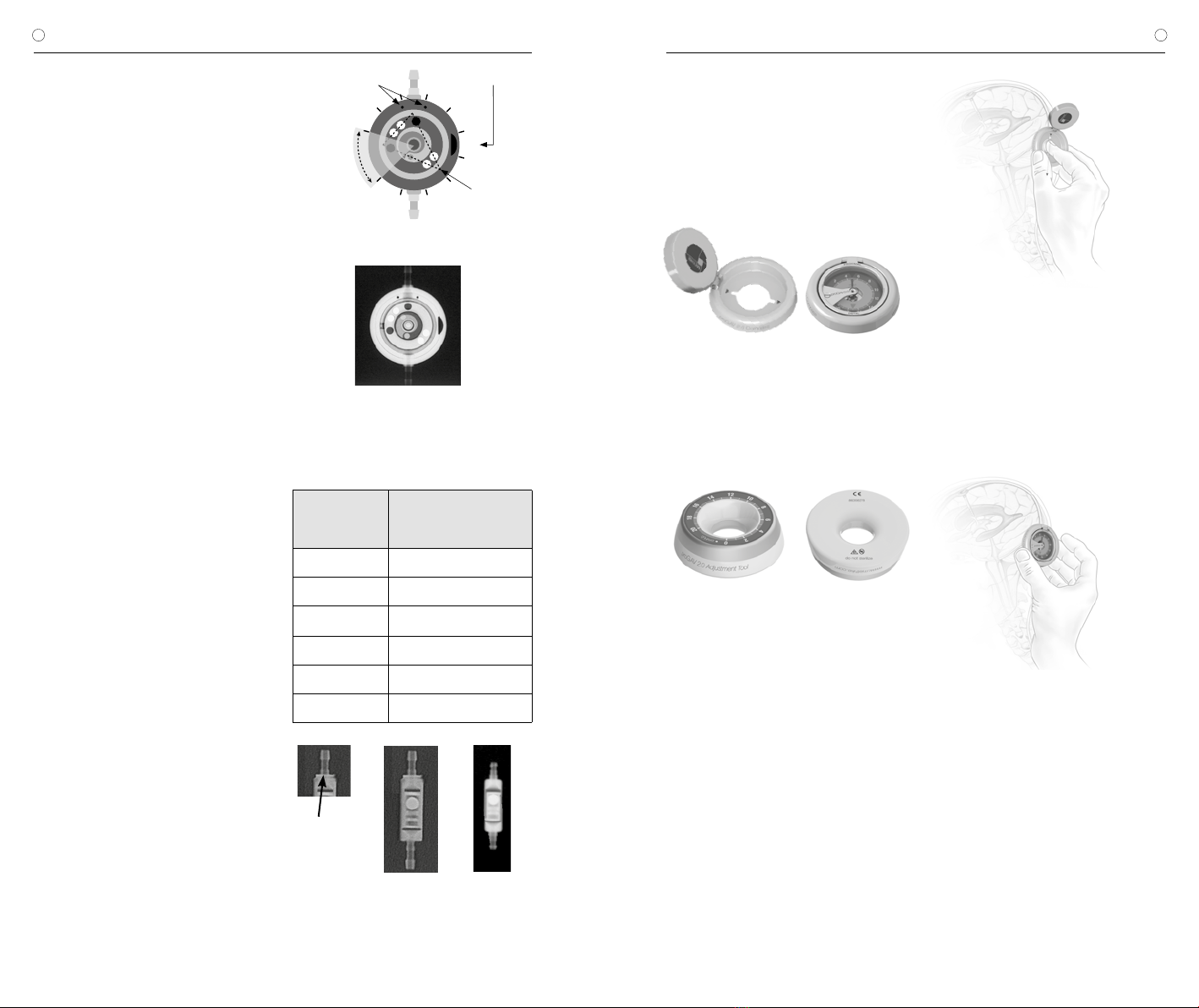
DRUCKSTUFENERKENNUNG IM
RÖNTGENBILD
Die eingestellte Druckstufe des proGAV 2.0
sollte immer mit dem proGAV 2.0 Kompass
kontrolliert werden, kann aber auch mittels
eines Röntgenbildes geprüft werden. Dabei ist
die Stellung des Rotors entscheidend. Die vier
Magnete im Rotor sind im Röntgenbild als wei-
ße Punkte zu erkennen und liegen sich paarig
gegenüber. Auf einer Seite des Rotors dienen
zwei zusätzliche Bohrungen - rechts und links
neben den beiden Magneten - zur Orientierung.
Sie sind als schwarze Punkte im Röntgenbild
erkennbar. Diese Seite kann als Rotorrücksei-
te bezeichnet werden. Gegenüber liegen die
beiden vorderen Magnete. Der Raum zwischen
diesen beiden Magneten kann als Dreieckspit-
ze betrachtet werden. Anhand der Richtung
dieses Zwischenraumes ist die Druckstufe ab-
lesbar. Bis auf den in Abb. 5 als nicht einstell-
baren Bereich gekennzeichneten Raum kann
die Dreieckspitze jede Position einnehmen.
Somit kann der Öffnungsdruck des proGAV 2.0
stufenlos von 0 bis auf 20 cmH2O eingestellt
werden. Um die Druckstufe nicht seitenverkehrt
abzulesen, ist das Ventil an einer Seite mit einer
Ventilmarkierung versehen, die im Röntgen-
bild schwarz sichtbar ist - bei einer Draufsicht
auf das implantierte Ventil wie in Abb. 6 ist die
Aussparung auf der rechten Seite sichtbar.
Dreieckspitze
Ventilmarkierung
Einlassmarkierungen
nicht
einstellbarer
Bereich
28
10
12
14
16
18
20
6
4
0
Abb. 5: schematische Darstellung des Rotors im
Röntgenbild
Abb. 6: Röntgenbild einer verstellbaren Differenzdruck-
einheit, Stellung 14 cmH2O
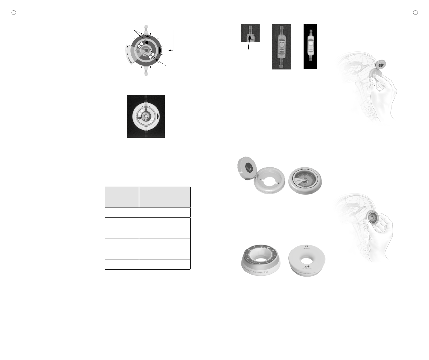
Im Röntgenbild sind die Druckstufen durch Ko-
dierungen zu erkennen. Folgende Druckstufen
sind für die Gravitationseinheit möglich:
Öffnungsdruck für
die vertikale
Position
Kodierung der
Gravitationseinheit
10 cmH2O kein Ring, klein (s. Abb. 7b)
15 cmH2O kein Ring, groß
20 cmH2O 1 Ring, groß (s. Abb. 7a)
25 cmH2O 2 Ringe, groß
30 cmH2O 3 Ringe, groß
35 cmH2O 4 Ringe, groß
Abb. 7: Röntgenbild der Gravitationseinheit
a) groß, 1 Ring = 20 cmH2O,
b) klein, kein Ring = 10 cmH2O
Kodierungsring
a) b)
ANWENDUNG DER INSTRUMENTE
Mit dem proGAV 2.0 Instrumente Set kann die
gewählte Druckstufe des proGAV 2.0 ermittelt,
verändert und kontrolliert werden.
Der proGAV 2.0 Kompass dient dem Loka-
lisieren und Auslesen der Verstelleinheit des
proGAV 2.0.
a) b)
Abb. 8: proGAV 2.0 Kompass
a) geöffnet b) geschlossen
Mit dem proGAV 2.0 Verstellinstrument kann
der Öffnungsdruck der Verstelleinheit des
proGAV 2.0 von 0 bis 20 cmH2O eingestellt
werden.
Abb. 9: proGAV 2.0 Verstellinstrument
Der Öffnungsdruck der verstellbaren Diffe-
renzdruckeinheit kann vor oder nach der
Implantation verändert werden. Er ist vom
Hersteller auf 5 cmH2O voreingestellt. Um eine
Verstellung des Ventils vorzunehmen, müssen
folgende Schritte ausgeführt werden:
1. Lokalisierung
Klappt man das Instrument auf, wird eine
Schablone sichtbar, durch die man mit
dem Zeigefinger das Ventil am Kopf des
Patienten lokalisieren kann (Abb. 10).
Abb. 10: Lokalisieren des Ventils mit dem
proGAV 2.0 Kompass
Anschließend wird die Schablone des proGAV
2.0 Kompass zentriert auf das Ventil aufgesetzt.
Die Richtungsmarkierungen „proximal“ und „di-
stal“ zeigen die Flussrichtung an.
2. Prüfvorgang
Wenn man nun den Kompass hinunter klappt,
wird die Druckstufe automatisch angezeigt.
Abb. 11 : Ermittlung der Druckstufe mit dem
proGAV 2.0 Kompass
Vorsichtsmaßnahmen: Der proGAV 2.0 Kom-
pass sollte möglichst mittig auf das Ventil
aufgesetzt werden, sonst kann es zu einer
fehlerhaften Bestimmung des Öffnungs-
druckes kommen.
Der proGAV 2.0 Kompass reagiert empfindlich
auf externe Magnetfelder. Um unerwünschte
Wechselwirkungen auszuschließen, sollte das
proGAV 2.0 Verstellinstrument bei der Bestim-
mung des Öffnungsdrucks nicht in unmittel-
barer Nähe zum proGAV 2.0 Kompass liegen.
Wir empfehlen einen Abstand von mindestens
30 cm.

89
| GEBRAUCHSANWEISUNG proGAV 2.0 GEBRAUCHSANWEISUNG |proGAV 2.0
DE DE
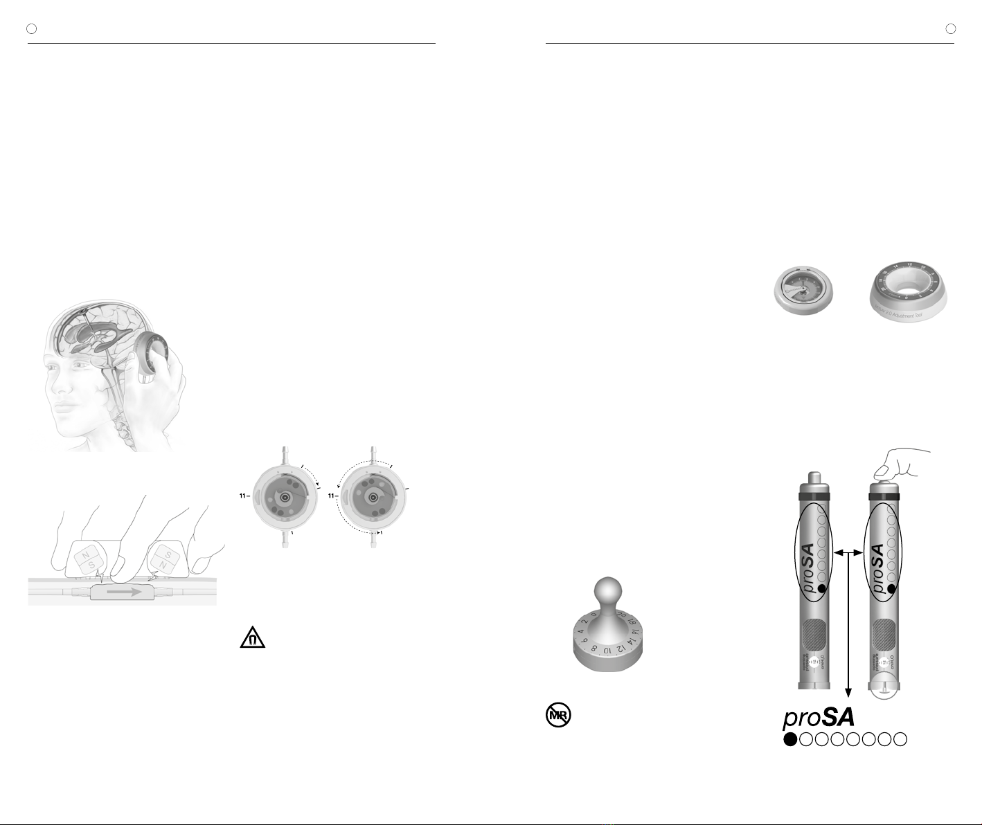
3. Verstellvorgang
Das proGAV 2.0 Verstellinstrument wird zen-
triert über dem Ventil positioniert. Mit Hilfe des
Zeigefingers kann man das Ventil über die Aus-
sparung in der Mitte des Instruments sehr gut
ertasten, um das Instrument korrekt zu platzie-
ren. Dabei muss die gewünschte Druckstufe
auf der Skala in Richtung des Ventileinlasses
bzw. des Ventrikelkatheters zeigen. Durch
leichten Druck mit dem Zeigefinger auf die Ver-
stelleinheit wird die Rotorbremse gelöst und die
proGAV 2.0 - Druckstufe verändert.
a)
b)
Abb. 12: a) und b))
Verstellung mit dem proGAV 2.0 Verstellinstrument
Das proGAV 2.0 ist mit einem Feedbackme-
chanismus ausgestattet. Wird Druck auf das
Ventil ausgeübt, ist aufgrund der Beschaffen-
heit des Ventilgehäuses ein akustisches Signal
- ein Klickton - hörbar bzw. ein Widerstand
fühlbar sobald die Rotorbremse gelöst ist. Das
Ventil zeigt also akustisch bzw. haptisch an,
wann der Druck für eine Entkopplung ausreicht.
Wird dieser Druck anschließend wieder gelöst,
ist der Rotor wieder verstellsicher. Während das
Klicken beim Lösen der Rotorbremse vor der
Implantation immer gut zu hören ist, kann es
nach der Implantation und Befüllung des Ventils
je nach Lage und Beschaffenheit der Implan-
tatumgebung deutlich gedämpft sein. In der
Regel sollte es aber durch den Patienten selbst
oder aber mittels eines Stethoskops hörbar
sein.
Achtung: Bei der Verstellung ist darauf zu
achten, dass der Öffnungsdruck um maxi-
mal 8 cmH2O pro Verstellvorgang verän-
dert wird, da es andernfalls zu Fehlern
kommen kann.
Beispiel: Der Öffnungsdruck soll von 3 auf
18 cmH2O verändert werden. Bei einem ein-
zigen Verstellvorgang würde sich der Rotor
falsch herum drehen (kurzer Weg) und bei der
Stellung 0 cmH2O anschlagen (Abb.13a). Rich-
tig ist die Verstellung in 2 Schritten: Verstellung
von 3 auf 11 und von 11 auf 18 cmH2O. Der
Rotor dreht sich richtig herum (Abb. 13b).
3
0
18
3
0
18
a) b)
Abb. 13: Rotordrehung bei Verstellung
a) falsche Richtung b) korrekt
Vorsichtsmaßnahmen: Vom proGAV
2.0 Verstellinstrument geht ein Ma-
gnetfeld aus. Metallische Gegenstände und
Magnetspeichermedien sollten einen hinrei-
chenden Sicherheitsabstand haben.
4. Prüfen nach Verstellung
Nach der Einstellung des Ventilöffnungsdruckes
wird eine Prüfung durchgeführt. Dazu wird wie
unter Punkt 1 und 2 vorgegangen. Sollte der
gemessene Druck nicht mit der gewünschten
Druckstufe übereinstimmen, wird der Verstell-
vorgang wiederholt. Dazu wird erneut bei Punkt
3 begonnen.
Durch die Schwellung der Haut kann die Einstel-
lung einige Tage postoperativ erschwert sein!
Ist die Prüfung der Ventileinstellung mit dem
proGAV 2.0 Kompass nicht eindeutig möglich,
ist eine Kontrolle durch ein bildgebendes Ver-
fahren zu empfehlen.
proGAV Verstellkreisel
Der proGAV Verstellkreisel wird steril ausgelie-
fert und ist resterilisierbar. Es ist also möglich,
eine Druckstufenänderung und Kontrolle vor
und während der Ventil-Implantation direkt am
proGAV 2.0 vorzunehmen.
Um die Druckstufe zu ermitteln, wird der
proGAV Verstellkreisel zentral auf das proGAV
2.0 gestellt. Der proGAV Verstellkreisel richtet
sich auf dem Ventil selbständig aus. Die Druck-
stufe ist in Richtung proximalem (zum Ventil füh-
renden) Katheter ablesbar.
Soll die Druckstufe verstellt werden, wird
der proGAV Verstellkreisel zentral auf das
proGAV 2.0 aufgesetzt. Dabei muss die ge-
wünschte Druckstufe in Richtung proximalem
(zum Ventil führenden) Katheter zeigen. Durch
leichten Druck mit dem proGAV Verstellkreisel
auf das Ventil wird die Rotorbremse im proGAV
2.0 gelöst und die Druckstufe eingestellt.
Bei der Verstellung ist darauf zu achten, dass
der Öffnungsdruck um maximal 8 cmH2O pro
Verstellvorgang verändert wird, da es andern-
falls zu Fehlern kommen kann (siehe Kapitel „3.
Verstellvorgang“).
Abb. 14: proGAV Verstellkreisel
Vorsichtsmaßnahmen: Aufgrund der
Magnete im Inneren der proGAV 2.0
Instrumente dürfen proGAV 2.0 Instrumente
nicht in der Nähe von aktiven Implantaten
wie z.B. Herzschrittmachern verwendet
werden. Weiter besteht im Umfeld von MRT-
Geräten die Gefahr, dass das MRT-Gerät be-
schädigt wird. Daher ist eine Benutzung der
proGAV 2.0 Instrumente dort nicht erlaubt!
EINSTELLUNG DER VERSTELLBAREN
DIFFERENZDRUCKEINHEIT
Es ist unbedingt erforderlich, sich vor der Be-
nutzung der Instrumente zu vergewissern,
dass:
für die verstellbare Differenzdruckeinheit
ausschließlich proGAV 2.0 Instrumente
a) b)
Abb. 15:
a) proGAV 2.0 Kompass
b) proGAV 2.0 Verstellinstrument
und bei einer Kombination von proGAV 2.0 mit
einer verstellbaren Gravitationseinheit für
die Verstellung von proSA ausschließlich
proSA Instrumente verwendet werden.
Abb. 16: proSA Verstellinstrument
10 11
| GEBRAUCHSANWEISUNG proGAV 2.0 GEBRAUCHSANWEISUNG |proGAV 2.0
DE DE
MÖGLICHE SHUNTKOMPONENTEN
Das proGAV 2.0 kann als Shunt System in ver-
schiedenen Konfigurationen bestellt werden. Die-
se Konfigurationen können mit nachfolgend kurz
vorgestellten Zubehörteilen kombiniert werden.
Dabei gibt es jeweils Varianten für den kindlichen
Hydrocephalus und weitere für den Normaldruck-
hydrocephalus (NPH) bei Erwachsenen.
Reservoire
Bei Verwendung von Shunt Systemen mit
einem Reservoir bestehen Möglichkeiten zur Li-
quorentnahme, Medikamentenapplikation und
Druckkontrolle.
Das SPRUNG RESERVOIR und das CONTROL
RESERVOIR ermöglichen durch ein zusätzliches
Rückschlagventil den Liquor in die ableitende
Richtung zu pumpen und damit sowohl eine
Kontrolle des distalen Drainageanteils, als auch
des Ventrikelkatheters durchzuführen. Während
des Pumpvorganges ist der Zugang zum Ven-
trikelkatheter verschlossen. Der Öffnungsdruck
des Shunt Systems wird durch den Einsatz die-
ser Reservoire nicht erhöht. Eine Punktion sollte
möglichst senkrecht zur Reservoiroberfläche
mit einem maximalen Kanülendurchmesser von
0,9 mm erfolgen. Es kann ohne Einschränkung
30 Mal punktiert werden.
Warnhinweis: Durch häufiges Pumpen kann
es zu einer übermäßigen Drainage und da-
mit zu unphysiologischen Druckverhältnis-
sen kommen. Der Patient sollte über diese
Gefahr aufgeklärt werden.
Bohrlochumlenker
Der Bohrlochumlenker bietet durch seinen
strammen Sitz auf dem Ventrikelkatheter die
Möglichkeit, die in den Schädel eindringende Ka-
theterlänge vor der Implantation zu wählen. Der
Ventrikelkatheter wird im Bohrloch rechtwinklig
umgelenkt (siehe Kapitel „Implantation“).
SCHLAUCHSYSTEME
Das proGAV 2.0 kann als einzelne Ventileinheit
oder als Shunt System mit integrierten Kathetern
(Innendurchmesser 1,2 mm, Außendurchmesser
2,5 mm) bestellt werden. Die mitgelieferten Ka-
theter verändern die Druck-Flow-Charakteristik
nicht grundlegend. Werden Katheter anderer
Hersteller benutzt, sollte auf einen strammen
Sitz geachtet werden. In jedem Fall müssen die
Katheter durch eine Ligatur sorgfältig an den
Titankonnektoren des Ventils befestigt werden.
IMPLANTATION
Platzierung des Ventrikelkatheters
Zur Platzierung des Ventrikelkatheters sind ver-
schiedene Operationstechniken möglich. Der
notwendige Hautschnitt sollte in Form eines
Läppchens mit Stielung in Richtung des ablei-
tenden Katheters erfolgen. Bei Verwendung
eines Bohrlochreservoirs sollte der Hautschnitt
nicht unmittelbar über dem Reservoir liegen. Es
sollte darauf geachtet werden, dass nach Anlage
des Bohrlochs die Öffnung der Dura möglichst
klein erfolgt, um ein Liquorleck zu vermeiden.
Das proGAV 2.0 ist in verschiedenen Konfigu-
rationen erhältlich: Bei Verwendung eines Bohr-
lochreservoirs wird zuerst der Ventrikelkatheter
implantiert. Nach dem Entfernen des Mandrins
kann die Durchgängigkeit des Ventrikelkatheters
durch Heraustropfen von Liquor überprüft wer-
den. Der Katheter wird gekürzt und das Bohr-
lochreservoir konnektiert, wobei die Konnektion
mit einer Ligatur gesichert wird.
Bei der Verwendung eines Shunt Systems mit
einer Vorkammer liegt ein Bohrlochumlenker bei.
Mithilfe dieses Umlenkers kann die zu implantie-
rende Katheterlänge eingestellt und in den Ven-
trikel vorgeschoben werden. Der Ventrikelkathe-
ter wird umgelenkt und die Vorkammer platziert.
Die Position des Ventrikelkatheters sollte nach
der Operation durch ein bildgebendes Verfahren
(z.B. CT, MRT) kontrolliert werden.
Platzierung des Ventils
Die verstellbare Differenzdruckeinheit des
proGAV 2.0 ist bei Anlieferung auf einen Öff-
nungsdruck von 5 cmH2O eingestellt. Dieser
Öffnungsdruck kann vor der Implantation auf
einen anderen Druck eingestellt werden.
Das proGAV 2.0 arbeitet lageabhängig. Es muss
deshalb darauf geachtet werden, dass die Gra-
vitationseinheit parallel zur Körperachse implan-
tiert wird. Daher sollte bei Verwendung eines
Shuntsystems, bei dem das Ventil mit einem
Bohrlochreservoir vorkonfektioniert ist, nur der
occipitale Zugang verwendet werden. Als Im-
plantationsort eignet sich die Platzierung hinter
dem Ohr, wobei die Implantationshöhe keinen
Einfluss auf die Funktion des Ventils hat. Die
verstellbare Differenzdruckeinheit sollte auf dem
Knochen bzw. dem Periost aufliegen, da wäh-
rend einer späteren Verstellung ein Druck auf das
Ventil aufgebracht werden muss. Es sollte ein
großer bogenförmiger oder ein kleiner gerader
Hautschnitt, dann mit zwei Taschen (proximal
vom Hautschnitt für die verstellbare Differenz-
druckeinheit und distal vom Hautschnitt für die
Gravitationseinheit) angelegt werden.
Der Katheter wird vom Bohrloch zum gewählten
Ventilimplantationsort vorgeschoben, wenn nö-
tig gekürzt, und am proGAV 2.0 mittels Ligatur
befestigt. Weder die verstellbare Differenzdruck-
einheit noch die Gravitationseinheit sollte sich
direkt unter dem Hautschnitt befinden. Beide
Ventileinheiten sind mit Pfeilen in Flussrichtung
(Pfeil nach distal bzw. nach unten) versehen.
Warnhinweis: Die verstellbare Differenz-
druckeinheit sollte nicht in einem Bereich
implantiert werden, der das Auffinden bzw.
Ertasten des Ventils erschwert (z. B. unter
stark vernarbtem Gewebe).
Warnhinweis: Die Katheter sollten nur mit ar-
mierten Klemmchen, nicht direkt hinter dem
Ventil unterbunden werden, da sie sonst ge-
schädigt werden können.
Platzierung des Peritonealkatheters
Der Ort des Zugangs für den Peritonealkathe-
ter liegt im Ermessen des Chirurgen. Er kann
z. B. waagerecht paraumbilikal oder transrek-
tal in Höhe des Epigastriums angelegt werden.
Ebenso können verschiedene Operationstech-
niken für die Platzierung des Peritonealkathe-
ters angewendet werden.
Es wird empfohlen, den Peritonealkatheter mit
Hilfe eines subkutanen Tunnelers vom Ventil
aus, eventuell mit einem Hilfsschnitt, bis zum
Ort der Platzierung durchzuziehen. Der Perito-
nealkatheter, der in der Regel fest am proGAV
2.0 befestigt ist, besitzt ein offenes distales
Ende und keine Wandschlitze.
Nach Öffnen des Peritoneums oder mithilfe
eines Trokars wird der ggf. gekürzte Peritoneal-
katheter in die freie Bauchhöhle vorgeschoben.
VENTILPRÜFUNG
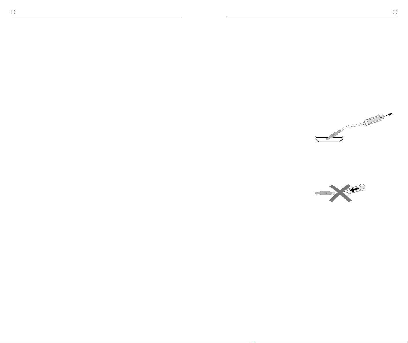
Präoperative Ventilprüfung
Das möglichst schonende Befüllen des Ven-
tils kann durch Aspirieren mithilfe einer am
distalen Katheterende aufgesetzten sterilen
Einwegspritze erfolgen. Dabei wird das Ventil
distal konnektiert und in sterile, physiologische
Kochsalzlösung gehalten. Lässt sich Kochsalz-
lösung entnehmen, ist das Ventil durchgängig
(Abb. 17).
Warnhinweis: Verunreinigungen in der zum
Testen verwendeten Lösung können die
Produktleistung beeinträchtigen.
Abb. 17: Durchgängigkeitsprüfung
Warnhinweis: Eine Druckbeaufschlagung
mittels Einwegspritze sollte sowohl am pro-
ximalen als auch am distalen Ende vermie-
den werden (Abb. 18).
Abb. 18: Vermeidung Druckbeaufschlagung
Postoperative Ventilprüfung
Das proGAV 2.0 ist als funktionssichere Einheit
ohne Pump- oder Prüfeinrichtung konstruiert
worden. Die Ventilprüfung kann durch Spülen,
Druckmessen oder Pumpen erfolgen.
12 13
| GEBRAUCHSANWEISUNG proGAV 2.0 GEBRAUCHSANWEISUNG |proGAV 2.0
DE DE
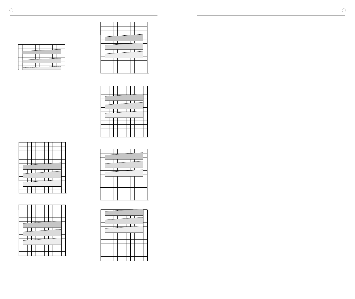
DRUCK-FLOW-CHARAKTERISTIK
Horizontale Ventilposition
Nachfolgend sind die Druck-Flow-Charakteristiken der verstell-
baren Differenzdruckeinheit des proGAV 2.0 beispielhaft für die
Druckstufe 0, 10 und 20 cmH2O in der horizontalen Ventilposition
dargestellt.
Abb. 19: Druck-Flow-Charakteristik für ausgewählte Druckstufen
der verstellbaren Differenzdruckeinheit
5
10
15
20
25
10 20 30 400 5 2515 35 45 50 55
30
Druck (cmH2O)
Flussrate (ml/h)
20 cmH2O
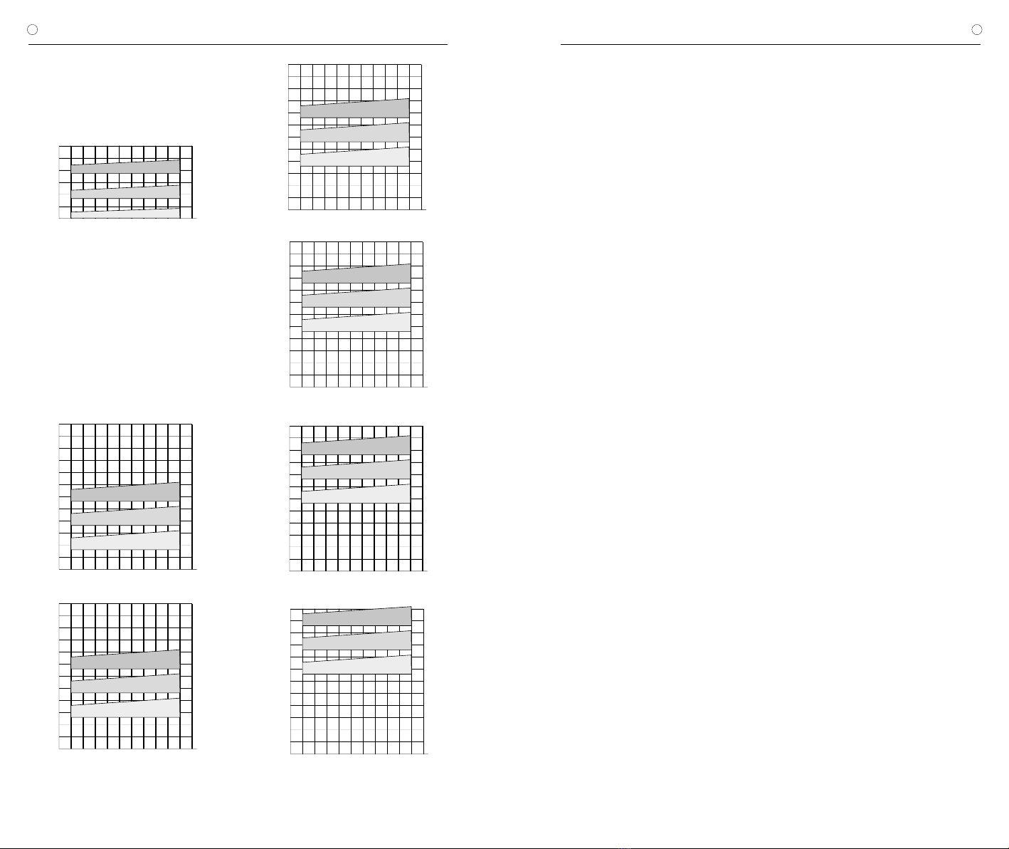
Vertikale Ventilposition
In der vertikalen Körperlage setzt sich der Öffnungsdruck des
proGAV 2.0 aus der Einstellung der verstellbaren Differenzdruck-
einheit und der Gravitationseinheit zusammen.
Nachfolgend ist die Druck-Flow-Charakteristik für verschiedene
Druckstufeneinstellungen in der vertikalen Körperposition darge-
stellt. Der gesamte Öffnungsdruck bezieht sich auf einen Referenz-
flow von 5ml/h. Für Flussraten von 20 ml/h sind die angegebenen
Drücke ca. 1-2 cmH2O höher.
5
10
15
20
25
10 20 30 40
052515 35 45 50 55
30
35
40
45
50
55
60
Druck (cmH2O)
a) Flussrate (ml/h)
20 cmH2O
10 cmH2O
0 cmH2O
5
10
15
20
25
10 20 30 400 52515 35 45 50 55
30
35
40
45
50
55
60
Druck (cmH2O)
b) Flussrate (ml/h)
20 cmH2O
10 cmH2O
0 cmH2O
Druck (cmH2O)
5
10
15
20
25
10 20 30 400 52515 35 45 50 55
30
35
40
45
50
55
60
c) Flussrate (ml/h)
20 cmH2O
10 cmH2O
0 cmH2O
5
10
15
20
25
10 20 30 400 52515 35 45 50 55
30
35
40
45
50
55
60
d) Flussrate (ml/h)
20 cmH2O
10 cmH2O
0 cmH2O
Druck (cmH2O)
e) Flussrate (ml/h)
5
10
15
20
25
10 20 30 400 52515 35 45 50 55
30
35
40
45
50
55
60
Druck (cmH2O)
20 cmH2O
10 cmH2O
0 cmH2O
5
10
15
20
25
10 20 30 400 5 2515 35 45 50 55
30
35
40
45
50
55
60
Druck (cmH2O)
f) Flussrate (ml/h)
20 cmH2O
10 cmH2O
0 cmH2O
VORSICHTSMASSNAHMEN UND
KONTRAINDIKATIONEN
Nach der Implantation müssen die Patienten
sorgfältig überwacht werden. Hautrötungen
und Spannungen im Bereich des Drainagege-
webes können ein Anzeichen von Infektionen
am Shunt System sein. Symptome wie Kopf-
schmerzen, Schwindelanfälle, geistige Ver-
wirrtheit oder Erbrechen treten häufig bei einer
Shuntdysfunktion auf. Diese Anzeichen, wie
auch eine Leckage am Shunt System, erfordern
den sofortigen Austausch der Shuntkompo-
nente oder auch des gesamten Shunt Systems.
Die Implantation von Medizinprodukten ist kon-
traindiziert, sofern beim Patienten eine Infektion
(z.B. Meningitis, Ventrikulitis, Peritonitis, Bakte-
riämie, Septikämie) oder der Verdacht auf eine
Infektion in der von der Implantation betroffenen
Körperregion vorliegt.
FUNKTIONSSICHERHEIT UND
VERTRÄGLICHKEIT MIT
DIAGNOSTISCHEN VERFAHREN
Die Medizinprodukte sind konstruiert worden,
um über lange Zeiträume präzise und zuverläs-
sig zu arbeiten. Es kann jedoch keine Garantie
dafür übernommen werden, dass die Medizin-
produkte nicht aus technischen oder medizi-
nischen Gründen ausgetauscht werden müs-
sen. Die Medizinprodukte halten den während
und nach der Operation auftretenden negativen
und positiven Drücken bis zu 200 cmH2O sicher
stand. Die Medizinprodukte sind stets trocken
und sauber zu lagern.
Kernspinresonanzuntersuchungen bis zu einer
Feldstärke von 3 Tesla oder computertomogra-
phische Untersuchungen können ohne Gefähr-
dung oder Beeinträchtigung der Ventilfunktion
durchgeführt werden. Das Ventil ist MR verträg-
lich. Die mitgelieferten Katheter sind MR sicher,
Reservoire, Umlenker oder Konnektoren sind
MR verträglich.
Warnhinweis: Bei anliegendem magne-
tischem Feld und gleichzeitigem Drücken
auf das Ventil kann eine Verstellung des
Ventils nicht ausgeschlossen werden. Im
MRT erzeugt das proGAV 2.0 Artefakte, die
größer sind als das Ventil selbst.
Warnhinweis für Träger von Herzschritt-
machern: Durch die Implantation eines
proGAV 2.0 kann möglicherweise die Funktion
des Herzschrittmachers beeinflusst werden.
NEBEN- UND WECHSELWIRKUNGEN
Bei der Hydrocephalustherapie mit Shunts kön-
nen, wie in der Literatur beschrieben, folgende
Komplikationen auftreten: Infektionen, Verstop-
fungen durch Eiweiß und/oder Blut im Liquor,
Über-/Unterdrainage oder in seltenen Fällen
Geräuschentwicklungen. Durch heftige Stöße
von außen (Unfall, Sturz, etc.) kann die Integrität
des Shunt Systems gefährdet werden.
Das proGAV 2.0 darf nicht in Verbindung mit
hydrostatischen Ventilen verwendet werden, da
es zu einem unphysiologisch erhöhten Ventri-
keldruck kommen kann. In Zweifelsfällen wen-
den Sie sich bitte an die Medizinproduktebera-
ter der Christoph Miethke GmbH & Co. KG.
STERILISATION
Die Produkte werden unter strenger Kontrolle
mit Dampf sterilisiert. Durch die Doppel-Verpa-
ckung in Steriltüten ist eine fünfjährige Sterilität
gewährleistet. Das jeweilige Verfallsdatum ist
auf der Verpackung angegeben. Bei Beschädi-
gung der Verpackung dürfen die Produkte auf
keinen Fall verwendet werden. Für die Funk-
tionssicherheit von resterilisierten Produkten
kann keine Garantie übernommen werden.
FORDERUNGEN DER MDD (RL 93/42/EWG)
Die Medizinprodukterichtlinie fordert die um-
fassende Dokumentation des Verbleibs von
medizinischen Produkten, die am Menschen
zur Anwendung kommen, insbesondere für
Implantate. Die individuelle Kenn-Nummer des
implantierten Ventils sollte aus diesem Grunde
in der Krankenakte und im Patientenpass des
Patienten vermerkt werden, um eine lückenlose
Rückverfolgbarkeit zu gewährleisten.
Die Übersetzung dieser Gebrauchsanweisung
in weitere Sprachen finden Sie auf unserer
Website (https://www.miethke.com/produkte/
downloads/).
Abb. 20: Druck-Flow-Charakteristiken der verfügbaren Druckstufen des proGAV 2.0
a) 10 cmH2O, b) 15 cmH2O, c) 20 cmH2O, d) 25 cmH2O e) 30 cmH2O, f) 35 cmH2O
10 cmH2O
0 cmH2O

15
INSTRUCTIONS FOR USE | GB
proGAV 2.0
14
| GEBRAUCHSANWEISUNG proGAV 2.0
DE
MEDIZINPRODUKTEBERATER
Die Christoph Miethke GmbH & Co. KG be-
nennt entsprechend den Forderungen der Me-
dizinprodukterichtlinie (RL 93/42/EWG) Medi-
zinprodukteberater, die Ansprechpartner für alle
produktrelevanten Fragen sind:
Dipl.-Ing. Christoph Miethke
Dipl.-Ing. Roland Schulz
Michaela Funk-Neubarth
Die Kontaktdaten sind auf der Rückseite dieser
Gebrauchsanweisung aufgeführt.
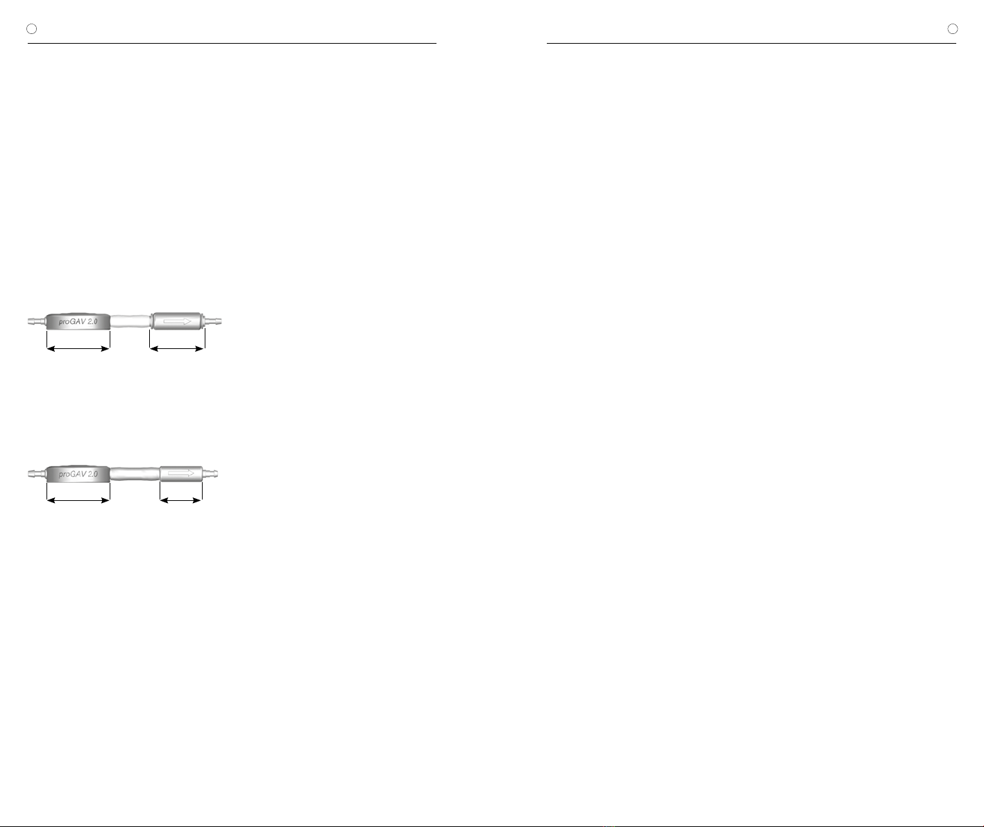
VARIANTEN
Höhe 4,5 mm Höhe 4,6 mm
17 mm 14,9 mm
Abb. 21: proGAV 2.0 mit Gravitationseinheit
(Öffnungsdruck in cmH20: 15, 20, 25, 30, 35)
Höhe 4,5 mm Höhe 4 mm
17 mm 11,5 mm
Abb. 22: proGAV 2.0 mit Gravitationseinheit
(Öffnungsdruck in cmH20: 10)
CONTENT
INDICATION 16
TECHNICAL DESCRIPTION 16
FUNCTION OF THE VALVE 16
SELECTION OF THE APPROPRIATE PRESSURE LEVEL 17
READING THE PRESSURE SETTING FROM AN X-RAY IMAGE 18
USING THE INSTRUMENTS 19
ADJUSTING THE ADJUSTABLE DP-UNIT 21
POSSIBLE SHUNT COMPONENTS 22
TUBE SYSTEMS 22
IMPLANTATION 22
VALVE TEST 23
PRESSURE-FLOW CHARACTERISTICS 24
PRECAUTIONS AND CONTRAINDICATIONS 25
FUNCTIONAL SAFETY AND COMPATIBILITY
WITH DIAGNOSTIC PROCEDURES 25
ADVERSE REACTIONS AND INTERACTIONS 25
STERILIZATION 25
REQUIREMENTS OF THE MDD 93/42/EEC 25
MEDICAL PRODUCTS CONSULTANTS 26
VARIATIONS 26

16 17
| INSTRUCTIONS FOR USE INSTRUCTIONS FOR USE |
GB GB
proGAV 2.0 proGAV 2.0
INDICATION
The proGAV 2.0 is used for cerebrospinal fluid
(CSF) drainage in the treatment of hydrocepha-
lus.
TECHNICAL DESCRIPTION
The proGAV 2.0 is a valve made from titanium.
It consists of an adjustable differential pressure
unit and a gravitational unit.
The adjustable differential pressure unit con-
sists of a stable titanium housing in which a
tried and tested ball cone valve (1) is integrated
in the proximal section. A torsion spring (2) de-
termines the opening pressure of this unit. The
pretension of the spring, and therefore the valve
opening pressure, can be adjusted through the
skin using a revolving rotor on a bearing (3).
Major components in the gravitational unit are
a tantalum ball (4), which defines the opening
pressure for this valve depending on the body
position and a sapphire ball (5), which ensures
precise closure.
FUNCTION OF THE VALVE
The proGAV 2.0 is a posture dependent hydro-
cephalus valve. The opening pressure for the
proGAV 2.0 is composed of the opening pres-
sures for the adjustable differential pressure unit
and the gravitational unit.
Horizontal position
In the horizontal position, the gravitational unit
is always open and does not present any re-
sistance.
Fig. 2: Gravitational unit in horizontal body position
Consequently, the opening pressure of the pro-
GAV 2.0 in the horizontal body position is cha-
racterised by the adjustable differential pressure
unit. The principal working method used by the
adjustable differential pressure unit is shown in
fig. 3a and b. In fig. 3 it is closed so that no
drainage is possible. In fig. 3b, the adjustable
differential pressure unit is shown in the open
state.
a)
b)
Fig. 3: Adjustable differential pressure unit in horizontal
body position
a) closed b) open
The intraventricular pressure (IVP) of the patient
is increased and the spring force which would
otherwise keep the differential pressure unit clo-
sed is overcome. Now, the sealing ball moves
out of the cone and a gap is sealing for liquor
drainage.
Vertical position
When the patient moves into an upright positi-
on, in that moment the gravitational unit closes
(fig. 4a). Now, additionally to the opening pres-
sure of the adjustable DP-unit, the weight of
the tantalum ball has to be exceeded (opening
pressure of the gravitational unit), thus the ope-
ning pressure of the proGAV 2.0 is significantly
increased. Only when the sum of the IVP and
the hydrostatic pressure exceeds the opening
pressure of the proGAV 2.0, drainage will be
possible again (fig. 4b).
a) b)
Fig. 4: Gravitational unit in vertical body position
a) closed b) open
During physical activity which is associated with
vibrations (for example jogging) the opening
pressure of the proGAV 2.0 can decrease tem-
porarily by 25 % to 35 % according to laborato-
ry results. This affects both the individual valve
and the combination with a gravitational unit. As
a basic principle, functionality is retained. At the
end of physical activity, the opening pressure
returns to its original level and remains stable.
SELECTION OF THE
APPROPRIATE PRESSURE LEVEL
Horizontal position
The opening pressure for the horizontal body
position is achieved using the adjustable diffe-
rential pressure unit. Here, the pressure stage
should be set in accordance with the clinical
picture and indications. Depending on the clini-
cal picture and age of the patient, the opening
pressure for this position can be selected bet-
ween pressure levels 0 and 20 cmH2O.
1 sapphire ball
2 torsion spring
3 rotor
4 tantalum ball
5 sapphire ball
Fig. 1: Schematic cross section of the proGAV 2.0
4
5
Adjustable differential pressure unit
(adjustable DP-unit)
Gravitational unit
1
2
3

18 19
| INSTRUCTIONS FOR USE INSTRUCTIONS FOR USE |
GB GB
proGAV 2.0 proGAV 2.0
Vertical position
The proGAV 2.0 opening pressure for the verti-
cal body position is calculated from the sum of
the opening pressure of the adjustable differen-
tial pressure unit and the gravitational unit. Pa-
tient size, activity level and potentially increased
abdominal pressure (obesity) should be taken
into account in selecting the opening pressure
for this position (see pressure level recommen-
dations at https://www.miethke.com/en/pro-
ducts/downloads/).
READING THE PRESSURE SETTING
FROM AN X-RAY IMAGE
The set pressure level of the proGAV 2.0 should
always be checked using the proGAV 2.0 Com-
pass, but it can also be checked using an x-ray
image. The rotor setting is decisive in this case.
The four magnets in the rotor can be seen on
the x-ray image as white points and are loca-
ted opposite each other in pairs. Two additio-
nal burrholes (right and left next to the magnet
pairs) on one side of the rotor can be used as
orientation. They can be seen as black points
on the X-ray image. This side can be designa-
ted as the rotor rear side. The two front ma-
gnets are opposite. The space between these
two magnets can be considered as the triangle
apex. The pressure level can be read off using
the orientation of this intermediate space. The
triangle apex can take up any position except
the space labelled as a non-adjustable area in
fig. 5. This means that the opening pressure of
the proGAV 2.0 can be infinitely variably adju-
sted from 0 up to 20 cmH2O. To ensure that the
pressure stage is not read off as a mirror image,
the valve is provided with a valve marking on
one side which is visible as black in the X-ray
image - on a plan view of the implanted valve
as in fig. 6 the recess on the right-hand side
is visible.
Non-adjustable
range
Triangle apex
Valve marking
Admittance markings
28
10
12
14
16
18
20
6
4
0
Fig. 5: Schematic representation of rotor in X-ray image
Fig. 6: X-ray image of an adjustable differential
pressure unit, setting 14 cmH2O
The pressure levels can be identified by coding
in the X-ray image. The following pressure levels
are possible for the gravitational unit:
Opening pressure for
the vertical position
Gravitationalt unit
coding
10 cmH2O no ring, small (Fig. 7b)
15 cmH2O no ring, large
20 cmH2O 1 ring, large (Fig. 7a)
25 cmH2O 2 rings, large
30 cmH2O 3 rings, large
35 cmH2O 4 rings, large
Fig. 7: X-ray image of the gravitational unit
a) 1 ring, large = 20 cmH2O,
b) no ring, small = 10 cmH2O
coding ring
a) b)
USING THE INSTRUMENTS
With the proGAV 2.0 Tool Set the selected ope-
ning pressure of the proGAV 2.0 can be deter-
mined, varied and controlled.
The proGAV 2.0 Compass is used to locate and
verify the DP adjustable unit.
a) b)
Fig. 8: proGAV 2.0 Compass
a) open b) closed
The proGAV 2.0 Adjustment Tool is used
for adjusting the valve opening pressu-
re of the proGAV 2.0 from 0 to 20 cmH2O.
Fig. 9: proGAV 2.0 Adjustment Tool
Each proGAV 2.0 is calibrated under strict
quality control procedures. The presetting of
the adjustable DP-unit is 5 cmH2O, but it must
be checked before implantation. The setting is
changed in the following steps:
1. Locating the valve
If the instrument is opened a template is visible
(fig. 10). Then the valve can be located on the
patient‘s head with the forefinger.
Fig. 10: Locating the valve with the
proGAV 2.0 Compass
The proGAV 2.0 Compass must be positioned
centrally on the valve. The markings on the in-
strument “proximal” and “distal” show the flow
direction.
2. Verifying the opening pressure
When the compass is closed, the pressure set-
ting is indicated automatically (fig. 11).
Fig. 11: Verifying the pressure setting with the
proGAV 2.0 Compass
Caution: Placing the proGAV 2.0 Compass in
a non-central position on the valve can lead
to erroneous readings!
The proGAV 2.0 Compass is sensitive to ex-
ternal magnetic fields. To exclude undesirable
interactions the proGAV 2.0 Adjustment Tool
should not be in the immediate vicinity of the
proGAV 2.0 Compass while determining the
opening pressure. We recommend a distance
of about 30 cm.
3. Adjusting the opening pressure
The proGAV 2.0 Adjustment Tool must be po-
sitioned centrally on the valve. For a correct
placement the valve should be palpated with
the forefinger through the opening in the middle

20 21
| INSTRUCTIONS FOR USE INSTRUCTIONS FOR USE |
GB GB
proGAV 2.0 proGAV 2.0
of the instrument. The desired pressure setting
must point on the scale in direction of the in-
let connector and the ventricular catheter. By
applying light pressure the rotorbrake will be
released and the pressure of the proGAV 2.0
can be changed.
a)
b)
Fig. 12: a) and b)
Adjustment with the proGAV 2.0 Adjustment Tool
The proGAV 2.0 is equipped with a feedback-
mechanism. When using the proGAV 2.0 Ad-
justment Tool, pressure on the housing of the
valve is created and a resulting acoustic signal
(a clicking sound) is produced due to the unique
construction of the valve housing. This clicking
sound indicates that the rotorbrake is released.
Now the rotor can rotate freely. Once the pres-
sure on the valve is released, a clicking sound is
heard and the rotorbrake is again locked safely
so that the valve is safe against spontaneous
re-adjustments.
The clicking sound is well recognizable before
implantation. However after implantation, once
the valve is filled up, depending on place and
texture of the surrounding area of the implant,
the acoustic signal could be considerably mut-
ed. The clicking sound should generally be au-
dible by the patient itself or via a stethoscope.
Caution: The new opening pressure set-
ting of the valve must not differ from the
measured opening pressure by more than
8 cmH2O in any one setting (see chapter 4
“verifying the adjustment”).
Example: Opening pressure is to be changed
from 3 to 18 cmH2O. With only one adjustment
procedure the rotor would turn in the wrong
direction (short way) and would stop at the po-
sition 0 cmH2O. The correct adjustment is in 2
steps: Adjustment from 3 to 11, and from 11 to
18 cmH2O. The rotor turns correctly.
3
0
18
3
0
18
a) b)
Fig. 13: Rotor rotation during adjustment
a) false b) correct
Caution: From proGAV 2.0 Adjust-
ment Tool a magnetic field ema-
nates. Metallic objects and magnetic
media storages should have a sufficient
safety margin.
4.Verifying the adjustment
After adjusting the valve by using the proGAV
2.0 Adjustment Tool, it must be verified using
the proGAV 2.0 Compass as described in step
2. If the measured pressure now differs from the
intended pressure level, the adjustment proce-
dure has to be repeated from step 3.
Due to postoperative swelling of the skin the
adjustment of the valve setting may be difficult
within the first few days.
If the pressure configuration of the valve cannot
be determined with complete certainly by the
proGAV 2.0 Compass, the use of imaging tech-
niques is recommended.
proGAV Check-mate
The proGAV Check-mate is delivered sterile
and is intended to be re-sterilised. It is possi-
ble to change and to verify an applied pressure
setting on the valve directly. To verify the actual
pressure setting the proGAV Check-mate has
to be put centrally over the valve. The proGAV
Check-mate will immediately start to move. If
it remains stable, the pressure setting can be
read in alignment to the inlet connector.
To adjust a new pressure setting, the proGAV
Check-mate has to be placed centrally over the
valve. The new pressure setting has to point
towards the proximal catheter (leading to the
ventricle). By pressing down slightly the proGAV
Check-mate, the brake of the valve is decou-
pled, the rotor turns and the opening pressure
of the proGAV 2.0 is changed.
Please be aware that the steps for changing
the pressure setting should not be more than
8 cmH2O per step.
Fig. 14: proGAV Check-mate
Caution: Due to magnets inside the
proGAV 2.0 Tools, do not use the pro-
GAV 2.0 Tools nearby pacemakers. Further
more do not use the proGAV 2.0 Tools near-
by MRI scanner, since ther is a danger of
damaging the MRI-scanner.
ADJUSTING THE ADJUSTABLE DP-UNIT
Please verify specifically before using any tool
for verifying or adjusting the opening pressure:
For the adjustable DP-unit use either the
proGAV 2.0 Tools
a) b)
Fig. 15:
a) proGAV 2.0 Compass
b) proGAV 2.0 Adjustment Tool
and with a combination of proGAV 2.0 with an
adjustable gravitational-unit, use only proSA
Tools
Fig. 16: proSA Adjustment Tool

22 23
| INSTRUCTIONS FOR USE INSTRUCTIONS FOR USE |
GB GB
proGAV 2.0 proGAV 2.0
POSSIBLE SHUNT COMPONENTS
The proGAV 2.0 can be ordered as a shunt sys-
tem in a range of configurations. The configura-
tions can be combined with the accessories pre-
sented in brief below. In each case, versions for
paediatric hydrocephalus and for normal pressu-
re hydrocephalus (NPH) in adults are available.
Reservoirs
The use of a reservoir in combination with shunt
systems provides options for the withdrawal of
cerebrospinal fluid, administration of drugs and
pressure control.
Due to the non-return valve of the
SPRUNG RESERVOIR and the CONTROL
RESERVOIR, cerebrospinal fluid can be pum-
ped towards the valve, thus making it possible
to check the distal part of the drainage system
as well as (proximal) ventricular catheter. Duri-
ng the pump action, access to the ventricular
catheter is closed. The use of reservoirs does
not increase the opening pressure of the shunt
system. A puncture should be performed as
perpendicular as possible to the reservoir
surface with a maximum cannula diameter of
0.9 mm. 30 punctures are possible without any
restrictions.
Warning notice: Frequent pumping can re-
sult in excessive drainage and thus lead
to pressure conditions outside the normal
physiological range. The patient should be
properly informed about this risk.
Burrhole deflector
Because of the tight fit on the ventricular cathe-
ter, the burrhole deflector makes it possible to
choose the length of catheter penetrating into
the skull prior to implantation. The ventricular ca-
theter is deflected at a right angle in the burrhole
(see chapter “Implantation”).
TUBE SYSTEMS
The proGAV 2.0 can be ordered as an individual
valve unit or as a shunt system with integrated
catheters (interior diameter 1.2 mm, exterior
diameter 2.5 mm). The supplied catheters do
not fundamentally change the pressure-flow
characteristics. If catheters by other manufac-
turers are used, a tight fit must be ensured. In
any case, catheters have to be carefully fixed
with a ligature to the valve’s titanium connec-
tors.
IMPLANTATION
Positioning the ventricular catheter
Several surgical techniques are available for po-
sitioning the ventricular catheter. The required
skin incision should be made in form of a lobule
pedicled towards the draining catheter. If a burr-
hole deflector is used, the skin incision should
not be located right above the reservoir. To avoid
CSF leakage, care should be taken that the dura
opening is kept as small as possible after app-
lying the burrhole.
The proGAV 2.0 is available in a range of different
configurations: If a burrhole reservoir is used, the
ventricular catheter is implanted first. Once the
introducing stylet has been removed, the paten-
cy of the ventricular catheter can be tested by
checking if cerebrospinal fluid is dripping out.
The catheter is shortened and connected the
burrhole reservoir connected, with the connec-
tion secured with a ligature. A shunt system with
prechamber comes with a burrhole deflector.
The deflector is used for adjusting the length of
catheter to be implanted and for its positioning
inside the ventricle. The ventricular catheter is
deflected and the prechamber is put into place.
The position of the ventricular catheter should be
checked after implantation by imaging (such as
CT or MRI).
Positioning the valve
The proGAV 2.0 operates depending on its po-
sition. You must therefore ensure that the gra-
vitational unit is implanted parallel to the body
axis. Therefore, if a Shunt System in which the
valve has been pre-fitted with a burrhole reser-
voir, only the occipital access should be used.
A location behind the ear is suitable as an im-
plantation position, whereby the implantation
height has no influence on the valve function.
The adjustable differential pressure unit should
be contacting the bone or the periosteum since
pressure must be exerted on the valve during
any later adjustment. A large arch-shaped or a
smaller straight skin incision should be made,
which is then provided with two pockets (proxi-
mal from the incision for the adjustable differen-
tial pressure unit and distal from the incision for
the gravitational unit).
The catheter is then pushed forward from the
burrhole to the selected valve implantation lo-
cation, shortened if necessary, and secured to
the proGAV 2.0 with a ligature. Neither the ad-
justable differential pressure unit nor the gravita-
tional unit should be located directly under the
skin incision. Both valve units have been provi-
ded with an arrow in the flow direction (arrow
towards distal or downwards).
Warning notice: The adjustable differential
pressure unit should not be implanted in an
area which makes the detection or palpation
of the valve difficult (e.g. underneath heavily
scarred tissue).
Warning notice: The catheters should only
be blocked with a sheathed clamp and not
directly behind the valve as they might be
damaged otherwise.
Positioning the peritoneal catheter
The place of access site for the peritoneal catheter
is left to the surgeon’s discretion. It can be applied
e. g. para-umbilically in a horizontal direction
or transrectally at the height of the epigastri-
um. Likewise, various surgical techniques are
available for positioning the peritoneal catheter.
We recommend pulling through the peritoneal
catheter, using a subcutaneous tunneling tool
and perhaps with an auxiliary incision, from the
shunt to the intended position of the catheter.
The peritoneal catheter, which is usually securely
attached to the proGAV 2.0, has an open distal
end, but no wall slits. Following the exposure of,
and the entry into, the peritoneum by means of
a trocar, the peritoneal catheter (shortened, if ne-
cessary) is pushed forward into the open space
in the abdominal cavity.
VALVE TEST
Preoperative valve test
The most careful way of filling the valve is by
aspiration through a sterile single-use syrin-
ge attached to the distal end of the catheter.
The distal end of the valve is connected and
immersed in a sterile physiological saline soluti-
on. The valve is patent if saline solution can be
extracted (fig. 17).
Warning notice: Contamination in the soluti-
on used for testing can impair the product‘s
performance.
Fig. 17: Patency test
Warning notice: Pressurisation by the sin-
gle-use syringe should be avoided both at
the proximal and the distal end (fig. 18).
Fig. 18: Avoidance of pressurisation
Postoperative valve test
The proGAV 2.0 has been constructed as a
reliably functioning unit without pump or test
function. The valve test can be performed by
flushing, pressure measurement or pumping.
24 25
| INSTRUCTIONS FOR USE INSTRUCTIONS FOR USE |
GB GB
proGAV 2.0 proGAV 2.0
PRESSURE-FLOW CHARACTERISTICS
The pressure flow characteristics of the adjustable differential pres-
sure unit in the proGAV 2.0 are shown as an example for pressure
levels 0, 10 and 20 cmH2O in the horizontal valve position below.
Fig. 19: Pressure flow characteristics for selected pressure levels
of the adjustable differential pressure unit
5
10
15
20
25
10 20 30 400 5 2515 35 45 50 55
30
pressure ( cmH2O)
Flow (ml/h)
20 cmH2O
10 cmH2O
0 cmH2O
Vertical valve position
The opening pressure of the proGAV 2.0 in the vertical position
is the sum of the opening pressure of the adjustable DP-unit and
the gravitational unit.
The following diagrams (see fg. 21) show the pressure-flow-cha-
racteristics for some pressure settings in the vertical body position.
The total opening pressure refers to a reference flow of 5 ml/h.
When the flow rates reach 20 ml/h, the opening pressures are ap-
proximately 1-2 cmH2O higher.
5
10
15
20
25
10 20 30 40
052515 35 45 50 55
30
35
40
45
50
55
60
Pressure ( cmH2O)
a) Flow Rates (ml/h)
20 cmH2O
10 cmH2O
0 cmH2O
5
10
15
20
25
10 20 30 400 52515 35 45 50 55
30
35
40
45
50
55
60
Pressure ( cmH2O)
b) Flow Rates (ml/h)
20 cmH2O
10 cmH2O
0 cmH2O
5
10
15
20
25
10 20 30 400 52515 35 45 50 55
30
35
40
45
50
55
60
Pressure ( cmH2O)
c) Flow Rates (ml/h))
20 cmH2O
10 cmH2O
0 cmH2O
5
10
15
20
25
10 20 30 400 52515 35 45 50 55
30
35
40
45
50
55
60
Pressure ( cmH2O)
d) Flow Rates (ml/h)
20 cmH2O
10 cmH2O
0 cmH2O
5
10
15
20
25
10 20 30 400 52515 35 45 50 55
30
35
40
45
50
55
60
Pressure ( cmH2O)
e) Flow Rates (ml/h)
20 cmH2O
10 cmH2O
0 cmH2O
5
10
15
20
25
10 20 30 400 5 2515 35 45 50 55
30
35
40
45
50
55
60
Pressure ( cmH2O)
f) Flow Rates (ml/h)
20 cmH2O
10 cmH2O
0 cmH2O
PRECAUTIONS AND
CONTRAINDICATIONS
Patients must be carefully monitored after im-
plantation. Reddening of skin or tightness in the
area of the drained tissue may be indications of
infections at the shunt system. Symptoms such
as headache, dizziness, confusion or vomiting
often occur in conjunction with shunt dysfunc-
tion. These symptoms and a leakage within the
shunt system require the immediate replace-
ment of the affected shunt component or the
entire shunt system.
The implantation of medical devices is contra-
indicated if the patient has an infection or su-
spected infection (e.g. meningitis, ventriculitis,
peritonitis, bacteriaemia, septicaemia) in the
region affected by the implantation.
FUNCTIONAL SAFETY
AND COMPATIBILITY WITH
DIAGNOSTIC PROCEDURES
These medical devices are constructed in such
a way as to ensure their precise and reliable
operation over long periods of time. However,
no guarantee can be given that these medical
devices may not require replacement for me-
dical or technical reasons. These medical de-
vices are able to resist positive and negative
pressures up to 200 cmH2O during and after
implantation. These medical devices have to
be stored in a clean and dry environment at all
times.
Nuclear magnetic resonance examinations up
to a field strength of 3 Tesla or computed tomo-
graphy examinations can be performed without
risk or impairment to the valve function. The
valve is MR Conditional. Supplied catheters are
MR Safe. Reservoirs, deflectors and connec-
tors are MR Conditional.
Warning notice: If a magnetic field is being
applied and pressure is applied to the valve
at the same time, it is not possible to rule
out valve adjustment. In MRI the proGAV 2.0
creates artefacts which are larger than the
valve itself.
Warning notice for people using cardiac
pacemakers: it is possible that the function
of the heart pacemaker is influenced by the
implementation of a proGAV 2.0.
ADVERSE REACTIONS AND
INTERACTIONS
In the treatment of hydrocephalus with shunts,
the following complications may arise (as de-
scribed in the literature): infections, blockages
caused by protein and/or blood in the cerebro-
spinal fluid, over/under drainage or in very rare
cases noise development. Violent shocks from
the outside (accident, fall) may put the integrity
of the shunt system at risk.
The proGAV 2.0 must not be used in conjunc-
tion with hydrostatic valves as this may result
in increased ventricular pressure outside of the
physiological range. In case of doubt, please
contact the medical products consultants at
Christoph Miethke GmbH & Co. KG.
STERILISATION
The products are sterilised with steam under
strictly controlled conditions. The double wrap-
ping in sterile bags ensures sterility for a five-
year period. The expiry date is printed on the
wrapping of each individual product. If the pa-
ckaging is damaged, the product must not be
used in any circumstances. No guarantee can
be given for the functional safety and reliability
of resterilised products.
REQUIREMENTS OF THE MDD 93/42/EEC
The Medical Device Directive requires the com-
prehensive documentation of the whereabouts
of medical devices used in humans. The indivi-
dual identification number of the implanted val-
ve should therefore be recorded in the patient’s
medical records and patient data card to ensu-
re complete traceability.
Translations of these instructions for use into
additional languages can be found on our web-
site (https://www.miethke.com/en/products/
downloads/).
Fig. 19: Graphs: proGAV 2.0 a) 10 cmH2O, b) 15 cmH2O, c) 20 cmH2O, d) 25 cmH2O, e) 30 cmH2O, f) 35 cmH2O
27
MODE D’EMPLOI |FR
proGAV 2.0
26
| INSTRUCTIONS FOR USE
GB proGAV 2.0
MEDICAL PRODUCTS CONSULTANTS
In compliance with the European directive
on medical devices (directive 93/42/EEC),
Christoph Miethke GmbH & Co. KG has no-
minated medical products consultants as
contacts for all product-related questions:
Dipl.-Ing. Christoph Miethke
Dipl.-Ing. Roland Schulz
Michaela Funk-Neubarth
Contact details can be found on the reverse of
these instructions for use.
VARIATIONS
Height 4,5 mm Height 4,6 mm
17 mm 14,9 mm
Fig. 21: proGAV 2.0 with gravitational unit
(Opening pressure in cmH20: 15, 20, 25, 30, 35)
17 mm 11,5 mm
Height 4,5 mm Height 4 mm
Fig. 22: proGAV 2.0 with gravitational unit
(Opening pressure in cmH20: 10)
TABLE DES MATIÈRES
INDICATION 28
DESCRIPTION TECHNIQUE 28
MODE DE FONCTIONNEMENT DE LA VALVE 28
SÉLECTION DU NIVEAU DE PRESSION APPROPRIÉ 29
DÉTECTION DU NIVEAU DE PRESSION SUR LA RADIOGRAPHIE 30
UTILISATION DES INSTRUMENTS 31
RÉGLAGE DE L‘UNITÉ À DIFFÉRENTIEL DE PRESSION AJUSTABLE 33
COMPOSANTES DE SYSTÈME DE DÉRIVATION POSSIBLE 34
SYSTÈMES DE CATHÉTERS 34
IMPLANTATION 34
CONTRÔLE DE LA VALVE 35
COURBE PRESSION/DÉBIT 36
MESURES DE PRÉCAUTION ET CONTRE-INDICATIONS 36
SÉCURITÉ DU FONCTIONNEMENT ET COMPATIBILITÉ 37
AVEC D‘AUTRES PROCÉDURES DE DIAGNOSTIC 37
EFFETS SECONDAIRES ET INTERACTIONS 37
STÉRILISATION 37
EXIGENCES DE LA DIRECTIVE 93/42/CEE
RELATIVE AUX APPAREILS MÉDICAUX 37
CONSEILS EN PRODUITS MÉDICAUX 38
VARIANTES 38

28 29
| MODE D’EMPLOI MODE D’EMPLOI |FRFR proGAV 2.0 proGAV 2.0
INDICATION
La proGAV 2.0 est est destinée au traitement
de l‘hydrocéphalie par dérivation du liquide
céphalo-rachidien.
DESCRIPTION TECHNIQUE
La proGAV 2.0 est une valve fabriquée en ti-
tane. Elle se compose d‘une unité à différentiel
de pression ajustable et d‘une unité opérant par
gravité (fig. 1).
L‘unité à différentiel de pression ajustable se
compose d‘un robuste boîtier en titane dans la
partie proximale duquel a été intégré une valve
à cône et bille confirmée (1). Une barre ressort
(2) définit la pression d‘ouverture de cette unité.
Via un rotor (3) en appui rotatif, il est possible de
modifier le réglage de la précontrainte du res-
sort, donc la pression d‘ouverture de la valve.
Les composants essentiels de l‘unité opérant
par gravité sont une bille en tantale (4) qui définit
la pression d‘ouverture de cette valve suivant
la position du corps, et une bille en saphir (5)
garantissant l‘obturation précise.
MODE DE FONCTIONNEMENT
DE LA VALVE
La proGAV 2.0 est une valve opérant en
fonction de la position du corps. La pression
d‘ouverture de la proGAV 2.0 se compose de
la somme des pressions d‘ouverture de l‘unité
à différentiel de pression ajustable et de l‘unité
opérant par gravité.
Position horizontale
L‘unité opérant par gravité est toujours ouverte
lorsque le corps est en position allongée, et elle
n‘oppose aucune résistance (fig. 2).
1 Bille en saphir
2 Barre ressort
3 Rotor
4 Bille en tantale
5 Bille en saphir
Fig. 1: Vu en coupe de la proGAV 2.0
4
5
Unité à différentiel
de pression ajustable
Unité opérant par gravité
1
2
3
Fig. 2: Unité opérant par gravité avec le corps
en position horizontale
Par conséquent, la pression d‘ouverture de la
proGAV 2.0 en position horizontale du corps
est caractérisée par l‘unité à différentiel de
pression ajustable. Le mode de fonctionnement
de principe de l‘unité à différentiel de pression
ajustable est représenté aux fig. 3a et b. Dans
la fig. 3a, elle est fermée de sorte qu‘aucun
drainage n‘est possible. Dans la fig. 3b l‘unité à
différentiel de pression ajustable est représen-
tée à l‘état ouvert.
a)
b)
Fig. 3: Unité à différentiel de pression ajustable
corps en position horizontale
a) fermée
b) ouverte
La pression intraventriculaire (PIV) du patient
est accrue et la force du ressort qui maintient si-
non l‘unité à différentiel de pression fermée est
vaincue. Maintenant, la bille obturatrice quitte le
cône, ce qui libère un interstice permettant de
drainer le liquide céphalorachidien.
Position verticale
Lorsque le patient se redresse, l‘unité gravita-
tionnelle s‘active et la pression d‘ouverture du
proGAV 2.0 augmente fortement (fig. 4a). Il faut
maintenant que le liquide vainque, en plus de
la pression d‘ouverture exercée par l’unité bil-
le en-cône, la force exercée par le poids de la
bille de tantale (pression d‘ouverture de l’unité
gravitationnelle). Ce n‘est qu‘une fois que la
somme de la pression intraventriculaire (IVP) et
de la pression hydrostatique dépasse la pressi-
on d‘ouverture des deux unités qu‘un drainage
devient à nouveau possible (fig. 4b).
a) b)
Fig. 4: Unité opérant par gravité avec le corps en
position verticale
a) fermée
b) ouverte
En cas d‘activité physique incluant des trépida-
tions (jogging par ex.), la pression d‘ouverture
de la proGAV 2.0 peut, selon les résultats en
laboratoire, diminuer d‘un quantum compris
entre 25 % et 35 %. Cela concerne la valve in-
dividuelle mais aussi la combinaison avec une
unité opérant par gravité. La fonctionnalité de-
meure fondamentalement préservée. Avec la fin
de l‘activité corporelle, la pression d‘ouverture
originelle revient de manière stable.
SÉLECTION DU NIVEAU
DE PRESSION APPROPRIÉ
Position horizontale
La pression d‘ouverture lorsque le corps est
en position horizontale est atteinte par l‘unité
à différentiel de pression ajustable. Toutefois, il
faudrait ici ajuster le niveau de pression au ta-
bleau pathologique et à l’indication. En fonction
du tableau pathologique et de l’âge du patient,
il est possible de choisir, pour cette position du
corps, une pression d’ouverture comprise entre
les niveaux de pression 0 et 20 cmH2O.
30 31
| MODE D’EMPLOI MODE D’EMPLOI |FRFR proGAV 2.0 proGAV 2.0
Position verticale
La pression d‘ouverture de la proGAV 2.0
lorsque le corps est en position verticale se
calcule à partir de la somme des pressions
d‘ouverture de l‘unité à différentiel de pressi-
on ajustable et de l‘unité opérant par gravité.
Au moment de choisir la pression d’ouverture
pour cette position du corps, il faudrait tenir
compte de la taille corporelle du patient, de
l‘activité et peut-être d‘une pression abdomi-
nale accrue (adiposité) (voir la recommandation
des niveaux de pression à l‘adresse https://
www.miethke.com/en/products/downloads/).
DÉTECTION DU NIVEAU DE PRESSION
SUR LA RADIOGRAPHIE
lLe niveau de pression réglé de la proGAV 2.0
devrait toujours être contrôlé avec la boussole
proGAV 2.0; toutefois, il est également possi-
ble de le vérifier via une image radiographique.
La position du rotor est décisive à ce titre. Sur
l‘image radiographique, les quatre aimants sont
reconnaissables (les points blancs) et deux
paires se font face. Sur un côté du rotor, deux
alésages supplémentaires - sur les côtés droit
et gauche à côté des deux aimants - servent
de moyen d‘orientation. Sur l‘image radiogra-
phique, ils sont reconnaissables sous forme
de points noirs. Ce côté peut être appelé le
côté dorsal du rotor. En face se trouvent les
deux aimants avant. L‘espace entre ces deux
aimants peut être considéré comme représen-
tant la pointe du triangle. Le niveau de pression
est lisible à l‘aide de la direction de cet espace
intermédiaire. Hormis la plage marquée sur la
fig. 5 comme étant non réglable, la pointe du
triangle peut prendre une position quelcon-
que. De la sorte, la pression d‘ouverture de la
proGAV 2.0 peut être réglée progressivement
entre 0 et 20 cmH2O. Pour ne pas lire le niveau
de pression à l‘envers, la valve comporte un
marquage sur un côté, marquage qui appa-
raît en noir sur l‘image radiographique: sur vue
de dessus de la valve implantée, comme à la
fig. 6, l‘évidement est visible sur le côté droit.
Pointe du triangle
Marquage de valve
Marquages d'admission
Plage
non
réglable
28
10
12
14
16
18
20
6
4
0
Fig. 5: Représentation schématique du rotor radio-
graphié
Fig. 6: Image radiographique d‘une unité à différentiel
de pression ajustable 14 cmH2O
Sur l‘image radiographique, les niveaux de
pression sont reconnaissables à des codages.
Les niveaux de pression suivants sont possi-
bles pour l‘unité opérant par gravité:
Pression d‘ouver-
ture pour la posi-
tion verticale
Codage de l‘unité opérant
par gravité
10 cmH2O pas de bague, petit (Fig. 7b)
15 cmH2O pas de bague, grand
20 cmH2O 1 bague, grand (Fig. 7a)
25 cmH2O 2 bagues, grand
30 cmH2O 3 bagues, grand
35 cmH2O 4 bagues, grand
Fig. 7: Image radiographique de l‘unité
opérant par gravité
a) 1 bague, grand = 20 cmH2O,
b) pas de bague, petit = 10 cmH2O
Bague de codage
a) b)
UTILISATION DES INSTRUMENTS
Le Set d‘instruments proGAV 2.0 permet de
déterminer, modifier et contrôler le niveau de
pression choisi pour la proGAV 2.0.
La Bousolle proGAV 2.0 sert à localiser et lire
l‘unité ajustable du proGAV 2.0.
a) b)
Fig. 8: Boussole proGAV2.0
a) ouvert b) fermé
L‘Instrument d‘ajustage proGAV 2.0 permet de
régler la pression d‘ouverture de l‘unité ajusta-
ble du proGAV 2.0 entre 0 et 20 cmH2O.
Fig. 9: Instrument d‘ajustage proGAV2.0
La pression d‘ouverture de l‘unité à différentiel
de pression ajustable peut être modifiée avant
ou après l‘implantation. Elle a été préréglée
par le fabricant sur 5 cmH2O. Pour modifier le
réglage de la valve, il faut passer par les étapes
suivantes:
1. Localisation
Lorsqu‘on déplie l‘instrument, un gabarit de-
vient visible, qui permet avec l‘index de lo-
caliser la valve sur la tête du patient. (Fig. 10)
Fig. 10: Localiser la valve avec la Boussole proGAV 2.0
Ensuite le gabarit de la Boussole proGAV 2.0
est placé centré sur la valve. Les marquages de
direction « proximal » et « distal » indiquent le
sens d‘écoulement.
2. Opération de contrôle
Lorsqu‘ensuite on déplie la boussole vers le
bas, le niveau de pression s‘affiche automa-
tiquement.
Fig. 11: Détermination du niveau de pression avec la
Boussole proGAV 2.0
Mesures de précaution : Il faut placer la
Boussole proGAV 2.0 le mieux centrée pos-
sible sur la valve, faute de quoi il y a risque
de déterminer une pression d‘ouverture er-
ronée.
La Boussole proGAV 2.0 réagit de façon sen-
sible aux champs magnétiques extrêmes. Pour
empêcher des interactions indésirables, il faut
que l‘Instrument d‘ajustage proGAV 2.0 ne se
32 33
| MODE D’EMPLOI MODE D’EMPLOI |FRFR proGAV 2.0 proGAV 2.0
trouve à proximité immédiate de la Boussole
proGAV 2.0 lors de la détermination de la pres-
sion d‘ouverture. Nous recommandons une di-
stance d‘au moins 30 cm.
3. Opération d‘ajustage
Positionner l‘Instrument d‘ajustage proGAV 2.0
centré au-dessus de la valve. Pour placer cor-
rectement l‘instrument, il est possible avec
l‘index de très bien détecter la valve par pal-
page via l‘évidement au milieu de l‘instrument.
Ce faisant, le niveau de pression souhaité sur
l‘échelle doit pointer en direction de l‘admission
de la valve et/ou du cathéter de valve. En exer-
çant une légère pression avec l‘index sur l‘unité
d‘ajustage, le frein du rotor est desserré et le ni-
veau de pression de la proGAV 2.0 est modifié.
a)
b)
Fig. 12: a) et b)
Modification du réglage avec l‘Instrument
d‘ajustage proGAV 2.0
Le proGAV 2.0 est équipé d‘un mécanisme
de feedback. Si une pression est exercée sur
la valve, un signal acoustique (un clic) se fait
entendre en raison de la nature du corps de
la valve, et une résistance mécanique est per-
ceptible dès que le frein du rotor est desserré.
La valve émet également un signal acoustique
et haptique lorsque la pression est suffisante
pour un découplage. Si cette pression cesse
ensuite d‘être exercée, le rotor est de nouveau
à l‘abri d‘un déréglage. Tandis que le clic lors du
desserrage du frein de rotor est toujours bien
audible avant l‘implantation, il peut se retrou-
ver nettement atténué après l‘implantation et le
remplissage de la valve, ceci suivant la position
du corps et la nature de l‘environnement de
l‘implant. Toutefois et en règle générale, ce clic
devrait rester audible soit par le patient soit par
le biais d‘un stéthoscope.
Attention: Lors de la modification du
réglage, il faut veiller à ce que la pression
d‘ouverture soit modifiée d‘au maximum 8
cmH2O par opération d‘ajustage faute de
quoi des erreurs risquent de se produire.
Exemple: On veut réajuster la pression
d‘ouverture de 3 sur 18 cmH2O. Au cours
d‘une seule opération d‘ajustage, le rotor tour-
nerait dans le mauvais sens (itinéraire court) et
venir buter contre la position 0 cmH2O (fig.13a).
L‘ajustage correct se fait en 2 étapes : Ajustage
de 3 sur 11 et de 11 sur 18 cmH2O. Le rotor
tourne dans le bons sens (fig. 13b).
3
0
18
3
0
18
a) b)
Fig. 13: Rotation du rotor pendant l‘ajustage
a) mauvais sens
b) sens correct
Mesures de précaution: L‘Instrument
d‘ajustage proGAV 2.0 émet un
champ magnétique. Les objets métalliques
et les supports d‘enregistrement magné-
tique doivent être maintenus à une distance
de sécurité suffisante.
4. Vérifier après l‘ajustage
Après le réglage de la pression d‘ouverture de
la valve, une vérification à lieu. Procéder à cette
fin comme aux points 1 et 2. Si la pression me-
surée n‘est pas conforme à la pression souha-
itée, l‘opération d‘ajustage doit être répétée.
À cette fin, il faut reprendre depuis le point 3.
Du fait de l‘enflure de la peau en phase post-
opératoire, le réglage peut être rendu plus diffi-
cile pendant quelques jours!
Si une vérification du réglage de la valve avec
la Boussole proGAV 2.0 n‘est visiblement pas
possible, il est recommandé d‘effectuer un con-
trôle par le biais d‘un procédé d‘imagerie.
Gyroscope d‘ajustage proGAV 2.0
Le Gyroscope d‘ajustage proGAV 2.0 est liv-
ré stérile et est restérilisable. Il est également
possible d‘effectuer une modification du niveau
de pression et un contrôle avant et pendant
l‘implantation de la valve directement sur le
proGAV 2.0.
Pour déterminer le niveau de pression, le Gyro-
scoperéglableproGAV 2.0 est placé centré sur le
proGAV 2.0. Le Gyroscope réglable proGAV 2.0
s‘oriente de lui-même sur la valve. Le niveau
de pression est lisible en direction du cathéter
proximal (conduisant à la valve). Pour modi-
fier le réglage du niveau de pression, le Gyro-
scope réglable proGAV 2.0 est placé centré sur
proGAV 2.0. À cette fin, le niveau de pression
souhaité doit pointer vers le cathéter proximal
(conduisant à la valve). Une légère pression ex-
ercée avec le Gyroscope réglable proGAV 2.0
sur la valve desserre le frein du rotor dans
proGAV 2.0 et règle le niveau de pression.
Lors de la modification du réglage, il faut veil-
ler à ce que la pression d‘ouverture soit mo-
difiée d‘au maximum 8 cmH2O par opération
d‘ajustage faute de quoi des erreurs risquent
de se produire (voir le chapitre « 3. Opération
d‘ajustage »),
Fig. 14: Gyroscope d‘ajustage proGAV
Mesures de précaution: En raison
des aimants à l‘intérieur des Instru-
ments proGAV 2.0, les Instruments proGAV
2.0 ne doivent pas être utilisés à proximité
d‘implants actifs tels que par ex. des sti-
mulateurs cardiaques. Il y a en outre risque,
dans l‘environnement d‘appareils IRM, que
l‘appareil IRM soit endommagé. Pour cette
raison, il n‘est pas permis d‘utiliser les Instru-
ments proGAV 2.0 dans cet environnement!
RÉGLAGE DE L‘UNITÉ À DIFFÉRENTIEL
DE PRESSION AJUSTABLE
Il est absolument nécessaire de veiller, avant
d‘utiliser les instruments, à ce que:
pour l‘unité à différentiel de pression aju-
stable soient utilisés exclusivement des
Instruments proGAV 2.0
a) b)
Fig. 15:
a) Boussolle proGAV 2.0
b) Instrument d‘ajustage proGAV 2.0
et, en cas de combinaison de proGAV 2.0 avec
une unité ajustable opérant par gravité
pour ajuster proSA, exclusivement des In-
struments proSA soient utilisés.
Fig. 16: Instrument d‘ajustage proSA

34 35
| MODE D’EMPLOI MODE D’EMPLOI |FRFR proGAV 2.0 proGAV 2.0
COMPOSANTES DE SYSTÈME
DE DÉRIVATION POSSIBLE
La proGAV 2.0 peut être commandée comme
système de dérivation en différentes configura-
tions. Ces configurations sont combinables avec
les accessoires brièvement présentés ci-après. Il
existe des variantes adaptées à l’hydrocéphalie
infantile et d‘autres destinées à l‘hydrocéphalie à
pression normale (HPN) chez l‘adulte.
Réservoirs
En cas d‘utilisation de systèmes de dérivation
avec réservoir, il est possible de prélever du li-
quide céphalo-rachidien, d‘appliquer des médi-
caments et de contrôler la pression.
Le SPRUNG RESERVOIR et le CONTROL RE-
SERVOIR permettent, grâce à une valve antire-
tour supplémentaire, de pomper le liquide dans
une tubulure d‘évacuation et d‘effectuer ainsi un
contrôle aussi bien de la partie distale du drai-
nage que du cathéter ventriculaire. Pendant le
pompage, l‘accès au cathéter ventriculaire est
fermé. L‘emploi de ces réservoirs n‘accroît pas la
pression d‘ouverture de système de dérivation.
Une ponction devrait avoir lieu le plus perpen-
diculairement possible à la surface du réservoir,
avec une canule de 0,9 mm de diamètre. La fon-
ction peut être réalisée 30 fois sans restriction.
Avertissement: Un pompage fréquent peut
entraîner un drainage excessif et donc des
conditions de pression non physiologiques. Il
convient d‘informer le patient d‘un tel danger.
Clip d‘angle pour le trou de trépan
Se trouvant fermement en assise sur le cathéter
ventriculaire, le clip d‘angle pour le trou de trépan
offre la possibilité de choisir la longueur de ca-
théter qui pénètrera dans le crâne. Dans le trou
de trépan, le cathéter ventriculaire est dévié à an-
gle droit (cf. le chapitre «Implantation»).
SYSTÈMES DE CATHÉTERS
Il est possible commander la proGAV 2.0
comme unité à valve individuelle ou comme
système de shuntage à cathéters intégrés (dia-
mètre intérieur 1,2 mm, diamètre extérieur 2,5
mm). Les cathéters livrés d‘origine ne modifient
pas fondamentalement la courbe pression/débit.
Si les cathéters d‘autres fabricants sont utilisés,
il faut veiller à une assise ferme. Quel que soit
le cas, il faut fixer soigneusement les cathéters
par une ligature contre les connecteurs en titane
de la valve.
IMPLANTATION
Placement du cathéter ventriculaire
Différentes techniques opératoires sont pos-
sibles pour placer le cathéter ventriculaire.
L’incision cutanée nécessaire devrait prendre la
forme d‘un petit lambeau avec pédicule en di-
rection du cathéter évacuant le liquide. En cas
d’utilisation d‘un réservoir pour trou de trépan, il
faudrait que l‘incision cutanée ne se trouve pas
directement au dessus du réservoir. Il faudrait
veiller à ce qu’après avoir placé le réservoir pour
trou de trépan le trou dans la dure-mère soit le
plus petit possible pour empêcher une fuite de
liquide céphalo-rachidien.
La proGAV 2.0 est disponible en différentes con-
figurations: Si un réservoir pour trou de trépan
est utilisé, le cathéter ventriculaire est implanté en
premier. Après avoir retiré le mandrin introducteur,
il est possible de vérifier l‘absence d’obstruction
dans le cathéter ventriculaire en laissant cou-
ler quelques gouttes de liquide. Le cathéter est
raccourci et le réservoir connecté, sachant que
la connexion est sécurisée par une ligature.
En cas d‘utilisation d‘un système de dérivation
avec préchambre, un clip d‘angle pour le trou de
trépan est joint. À l‘aide de ce clip, il est possible
de régler la longueur de cathéter à implanter
et de l‘introduire dans le ventricule. Le cathéter
ventriculaire est dévié et placé dans la précham-
bre. Après l‘opération, la position du cathéter
ventriculaire devrait être contrôlée selon un pro-
cédé d‘imagerie (par ex. CT, IRM).
Placement de la valve
Une unité à différentiel de pression ajustable du
proGAV 2.0 est, lors de sa livraison, réglée sur
une pression d‘ouverture de 5 cmH2O. Cette
pression d‘ouverture peut être réglée sur une
autre pression avant l‘implantation.
La proGAV 2.0 travaille en fonction de la posi-
tion du corps. Pour cette raison, il faut veiller
à ce que l‘unité opérant par gravité soit im-
plantée parallèlement à l‘axe du corps. Pour
cette raison, en cas d‘utilisation d‘un système
de shuntage dans lequel la valve est précon-
fectionnée équipée d‘un réservoir pour orifice
de trépanation, il ne faudrait utiliser que l‘accès
occipital. Comme lieu d‘implantation convient
un placement derrière l‘oreille, sachant que la
hauteur d‘implantation n‘a aucune influence sur
la fonction de la valve. L‘unité à différentiel de
pression ajustable devrait appliquer sur l‘os et/
ou le périoste vu que pendant un ajustage ulté-
rieur une pression doit être exercée sur la valve.
Il faudrait ménager une grande incision cutanée
en arceau ou une petite incision cutanée droite,
puis appliquer avec deux poches (en direction
proximale depuis l‘incision cutanée pour l‘unité
à différentiel de pression ajustable et en direc-
tion distale depuis l‘incision cutanée pour l‘unité
opérant par gravité).
Faire avancer le cathéter du trou de trépa-
nation vers le lieu d‘implantation de la valve
souhaité, le raccourcir si nécessaire et le fixer
contre la proGAV 2.0 au moyen d‘une ligature.
Ni l‘unité à différentiel de pression ajustable ni
l‘unité opérant par gravité ne doivent se trouver
directement sous l‘incision cutanée. Les deux
unités à valve sont munies de flèches pointant
dans le sens d‘écoulement (flèche en direction
distale et vers le bas).
Avertissement: Il ne faut pas implanter l‘unité
à différentiel de pression ajustable dans une
zone compliquant la localisation et/ou le pal-
page de la valve (par ex. sous un tissu forte-
ment cicatrisé).
Avertissement: Les cathéters ne doivent être
retenus qu‘avec de petites brides armées et
pas directement derrière la valve faute de
quoi ils risquent d‘être endommagés.
Placement du cathéter péritonéal
Le lieu d‘accès du cathéter péritonéal est la-
issé à la discrétion du chirurgien. Il peut être
placé par ex. à l‘horizontale en zone paraom-
bilicale, ou de façon transrectale à hauteur de
l‘épigastre. De même, différentes techniques
d‘opération peuvent être utilisées pour placer
le cathéter péritonéal. Il est recommandé
d‘amener le cathéter péritonéal jusque sur
l‘emplacement en s‘aidant d‘un tunnélisateur
subcutané depuis la valve, le cas échéant avec
une incision auxiliaire. D‘habitude solidement
fixé contre la valve, le cathéter péritonéal pré-
sente une extrémité distale ouverte et pas de
fentes pariétales. Après avoir ouvert le périto-
ine ou à l‘aide d‘un trocart, le cathéter périto-
néal le cas échéant raccourci est poussé vers
l‘intérieur de la cavité abdominale.
Réimplantation
Les produits qui avaient déjà implantés sont in-
terdits de réimplantation sur le même patient ou
tout autre patient.
CONTRÔLE DE LA VALVE
Contrôle préopératoire de la valve
Le remplissage de la valve le plus en douceur
possible peut avoir lieu au moyen d’une seringue
stérile à usage unique appliquée à l‘extrémité di-
stale du cathéter. Au cours de ce geste, la valve
est connectée à l‘extrémité distale et immergée
dans une solution physiologique. S‘il est possi-
ble de prélever de la solution physiologique iso-
tonique, c‘est que la continuité de passage dans
la valve est assurée (fig. 17).
Avertissement: Les impuretés dans la solu-
tion utilisée pour le test peuvent pénaliser la
performance du produit.
Fig. 17: Test de perméabilité
Avertissement: Il faut éviter une mise sous
pression, à l‘aide de la seringue à usage
unique, aussi bien à l‘extrémité proximale
qu‘à l‘extrémité distale (fig. 18).
Fig. 18: Prévention de la mise sous pression
Contrôle postopératoire de la valve
La proGAV 2.0 est une unité d‘un fonctionnement
sûr conçue sans dispositif de pompage ou de
vérification. Le contrôle de la valve peut avoir lieu
par rinçage, mesure de la pression ou pompage.

36 37
| MODE D’EMPLOI MODE D’EMPLOI |FRFR proGAV 2.0 proGAV 2.0
COURBE PRESSION/DÉBIT
Position horizontale
Voici les courbes pression/débit de l‘unité à différentiel de pression
réglable de la proGAV 2.0 en prenant comme exemple les niveaux
de pression 0, 10 et 20 cmH2O lorsque la valve se trouve en po-
sition horizontale.
Fig. 19: Courbe pression/débit pour des niveaux de pression
sélectionnés de l‘unité à différentiel de pression ajustable
5
10
15
20
25
10 20 30 400 5 2515 35 45 50 55
30
Pression (cmH2O)
Débit d‘écoulement (ml/h)
20 cmH2O
Position verticale
En position du corps verticale, la pression d‘ouverture de la
proGAV 2.0 se compose du réglable des pressions de l‘unité à
différentiel de pression ajustable et de l‘unité opérant par gravité.
Voici la courbe pression/débit pour différents réglages de niveaux
de pression lorsque le corps se trouve en position verticale.
5
10
15
20
25
10 20 30 40
052515 35 45 50 55
30
35
40
45
50
55
60
Pression (cmH2O)
a) Débit d‘écoulement (ml/h)
20 cmH2O
10 cmH2O
0 cmH2O
5
10
15
20
25
10 20 30 400 52515 35 45 50 55
30
35
40
45
50
55
60
Pression (cmH2O)
b) Débit d‘écoulement (ml/h)
20 cmH2O
10 cmH2O
0 cmH2O
Pression (cmH2O)
5
10
15
20
25
10 20 30 400 52515 35 45 50 55
30
35
40
45
50
55
60
c) Débit d‘écoulement (ml/h)
20 cmH2O
10 cmH2O
0 cmH2O
5
10
15
20
25
10 20 30 400 52515 35 45 50 55
30
35
40
45
50
55
60
d) Débit d‘écoulement (ml/h)
20 cmH2O
10 cmH2O
0 cmH2O
Pression (cmH2O)
e) Débit d‘écoulement (ml/h)
5
10
15
20
25
10 20 30 400 52515 35 45 50 55
30
35
40
45
50
55
60
Pression (cmH2O)
20 cmH2O
10 cmH2O
0 cmH2O
5
10
15
20
25
10 20 30 400 5 2515 35 45 50 55
30
35
40
45
50
55
60
Pression (cmH2O)
f) Débit d‘écoulement (ml/h)
20 cmH2O
10 cmH2O
0 cmH2O
Fig. 20: Courbes pression/débit pour les niveaux de pression disponibles de la proGAV 2.0
a)10 cmH2O, b) 15 cmH2O, c) 20 cmH2O, d) 25 cmH2O e) 30 cmH2O, f) 35 cmH2O
10 cmH2O
0 cmH2O
MESURES DE PRÉCAUTION ET CONTRE-
INDICATIONS
Après l‘implantation, les patients doivent être
attentivement surveillés. Les rougeurs de peau
et les tensions dans la zone tissulaire où passe
le drainage peuvent être un signe d‘infections
au contact du système de dérivation. Des sym-
ptômes tels que des maux de tête, vertiges,
confusion mentale ou vomissements se pro-
duisent fréquemment lors d‘un dysfonctionne-
ment du shunt. Ces signes annonciateurs ainsi
qu‘une fuite du système de dérivation requièrent
un changement immédiat du composant affecté
ou de l‘ensemble du système de dérivation.
L‘implantation de produits médicaux est cont-
reindiquée si le patient est suspecté présenter
une infection (par ex. méningite, ventriculite,
péritonite, bactériémie, septicémie) ou s‘il faut
craindre une infection dans la région du corps
affectée par l‘implantation.
SÉCURITÉ DU FONCTIONNEMENT ET
COMPATIBILITÉ AVEC D’AUTRES PROCÉ-
DURES DE DIAGNOSTIC
Les produits médicaux ont été conçus pour
fonctionner avec précision et fiabilité sur de
longues périodes. Il demeure toutefois impos-
sible de garantir que les produits médicaux ne
devront pas être remplacés pour des motifs
techniques ou médicaux. Les produits médi-
caux supportent de manière sûre les pressi-
ons positives et négatives jusqu‘à 200 cmH2O
engendrées pendant et après l‘opération. Les
produits médicaux doivent toujours être con-
servés au sec dans un endroit propre.
Les examens par résonance magnétique nu-
cléaire jusqu‘à une puissance de champ de
3 Tesla ou les tomographies assistées par or-
dinateur peuvent être réalisés sans danger et
sans risque de gêner le fonctionnement de la
valve. La valve est compatible avec l‘examen
IRM. Les cathéters livrés d‘origine sont sûrs à
l‘examen IRM. Les réservoirs, coudes et con-
necteurs sont compatibles avec l‘examen IRM.
Avertissement: En présence d‘un champ
magnétique appliqué avec exercice simul-
tané d‘une pression sur la valve, un dérégla-
ge de la valve ne peut pas être exclu. Dans
l‘IRM, la proGAV 2.0 génère des artefacts de
plus grande taille que la valve elle-même.
Avertissement à l‘intention des porteurs
de stimulateurs cardiaques: L‘implantation
d‘un proGAV 2.0 peut influencer le fonction-
nement du stimulateur cardiaque.
EFFETS SECONDAIRES ET INTERACTIONS
Dans la thérapie de l‘hydrocéphalie au moyen
de shunts, les complications suivantes, décrites
dans la littérature médicale, peuvent surgir : Infec-
tions, obstructions par l‘albumine et/ou le sang
présent(e)(s) dans le liquide céphalo-rachidien,
drainage excessif/insuffisant ou, dans des cas
très rares, génération de bruits. Des chocs vio-
lents de l‘extérieur (accident, chute, etc.) peuvent
menacer l‘intégrité du système de dérivation.
La proGAV 2.0 ne doit jamais être utilisée en
liaison avec des valves hydrostatiques vu le
risque d‘engendrer une pression ventriculaire
accrue non physiologique. En cas de doute,
veuillez s.v.p. vous adresser aux conseils en
produits médicaux de la société Christoph
Miethke GmbH & Co. KG.
STÉRILISATION
Les produits sont stérilisés à la vapeur dans le
cadre d‘un contrôle sévère. Une stérilité de cinq
ans est garantie grâce au double conditionne-
ment en sachets stériles. La date de pérempti-
on respective est mentionnée sur l‘emballage.
Si l‘emballage a été endommagé, les produits
ne doivent en aucun cas être utilisés. Aucune
garantie ne peut être assumée quant à la sécu-
rité de fonctionnement des produits restérilisés.
EXIGENCES DE LA DIRECTIVE 93/42/CEE
RELATIVE AUX APPAREILS MÉDICAUX
La directive relative aux produits médicaux re-
quiert de localiser de façon intégralement do-
cumentée les produits médicaux utilisés sur
le corps humain. Le numéro identifiant indivi-
duellement la valve implantée doit, pour cette
raison, être noté dans le dossier patient et sur la
carte du patient afin de garantir une traçabilité
sans lacune.

38
| MODE D’EMPLOI
FR proGAV 2.0
Vous trouverez la traduction de ce mode
d‘emploi dans d‘autres langues sur notre site In-
ternet (https://www.miethke.com/en/products/
downloads/).
CONSEILS EN PRODUITS MÉDICAUX
Conformément aux exigences énoncées dans
la Directive 93/42/CEE relative aux produits
médicaux, la société Christoph Miethke GmbH
& Co. KG mentionne les conseils en produits
médicaux officiant d‘interlocuteurs sur toutes
les questions relatives aux produits :
Christoph Miethke, ingénieur diplômé
Roland Schulz, ingénieur diplômé
Michaela Funk-Neubarth
Les coordonnées sont énoncées au dos du
présent mode d‘emploi.
VARIANTES
Hauteur 4,5 mm Hauteur 4,6 mm
17 mm 14,9 mm
Fig. 21: proGAV 2.0 avec unité opérant par gravité
(Pression d‘ouverture en cmH20: 15, 20, 25, 30, 35)
Hauteur 4,5 mm Hauteur 4 mm
17 mm 11,5 mm
Fig. 22: proGAV 2.0 avec petite unité opérant par gravité
(Pression d‘ouverture en cmH20: 10)
ÍNDICE DEL CONTENIDO
INDICACIÓN 40
DESCRIPCIÓN TÉCNICA 40
FUNCIONAMIENTO DE LA VÁLVULA 40
SELECCIÓN DEL NIVEL DE PRESIÓN ADECUADO 42
IDENTIFICACIÓN DE LOS NIVELES DE PRESIÓN EN LAS RADIOGRAFÍAS 42
USO DE LOS INSTRUMENTOS 43
AJUSTE DE LA UNIDAD DE PRESIÓN DIFERENCIAL AJUSTABLE 45
POSIBLES ELEMENTOS DE DERIVACIÓN 46
SISTEMAS DE TUBOS 46
IMPLANTACIÓN 46
COMPROBACIÓN DE LA VÁLVULA 47
CURVA CARACTERÍSTICA DE PRESIÓN-CAUDAL 48
PRECAUCIONES Y CONTRAINDICACIONES 49
SEGURIDAD FUNCIONAL Y COMPATIBILIDAD
CON PROCEDIMIENTOS DE DIAGNÓSTICO 49
EFECTOS SECUNDARIOS E INTERACCIONES 49
ESTERILIZACIÓN 49
REQUISITOS DE LA DIRECTIVA SOBRE PRODUCTOS
SANITARIOS 93/42/CEE 50
ASESOR DE PRODUCTOS SANITARIOS 50
VARIANTES 50
Table of contents
Languages:
Other MIETHKE Medical Equipment manuals


