MIETHKE miniNAV User manual
Gebrauchsanweisung | Instructions for use |
Instrucciones de manejo | Instrukcja Stosowania
PL
GB
E
D
0297
CHRISTOPH MIETHKE GMBH & CO. KG
miniNAV®
This Instructions for Use is NOT intended for United State users. Please discard.
The Instructions for Use for United States users can be obtained by visiting our website at www.aesculapusa.com
and clicking the "Products" menu. If you wish to obtain a paper copy of the Instructions for Use, you may request
one by contacting your local Aesculap representative or Aesculap's customer service at 1-800-282-9000.
A paper copy will be provided to you upon request at no additional cost.
USA


3
GEBRAUCHSANWEISUNG |D
INHALTSVERZEICHNIS
INDIKATION 4
TECHNISCHE BESCHREIBUNG 4
PHYSIKALISCHER HINTERGRUND 5
ARBEITSWEISE DES VENTILS 6
AUSWAHL DES GEEIGNETEN VENTILS 6
MÖGLICHE SHUNTKOMPONENTEN 6
SCHLAUCHSYSTEME 7
OPERATIONSABLAUF 7
PRÄOPERATIVE VENTILPRÜFUNG 8
WIEDERHOLUNGSIMPLANTATIONEN 8
VORSICHTSMASSNAHMEN 8
VERTRÄGLICHKEIT MIT DIAGNOSTISCHEN VERFAHREN 8
POSTOPERATIVE VENTILPRÜFUNG 8
FUNKTIONSSICHERHEIT 8
NEBENWIRKUNGEN 9
STERILISATION 9
ERNEUTE STERILISATION 9
DRUCK-FLOW-CHARAKTERISTIK 9
MEDIZINPRODUKTEBERATER 10
FORDERUNGEN DER MEDIZINPRODUKTERICHTLINIE RL 93/42/EEC 10
KOMMENTAR ZUR GEBRAUCHSANWEISUNG 10
ALLGEMEINE INFORMATIONEN 10
VARIANTEN 11
4
| GEBRAUCHSANWEISUNG
D
INDIKATION
Das miniNAV dient beim Hydrocephalus zur
Liquordrainage aus den Ventrikeln in das Peri-
toneum.
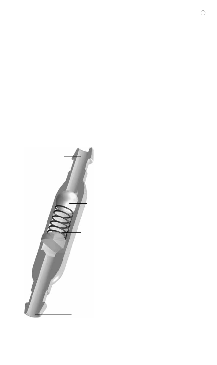
TECHNISCHE BESCHREIBUNG
Das miniNAV wurde mit dem Ziel entwickelt
ein möglichst kleines Ventil mit zuverlässiger
Drainagekontrolle anzubieten und gleichzeitig
die bekannten Probleme wie Verstopfung und
Abhängigkeit vom Subkutandruck zu vermei-
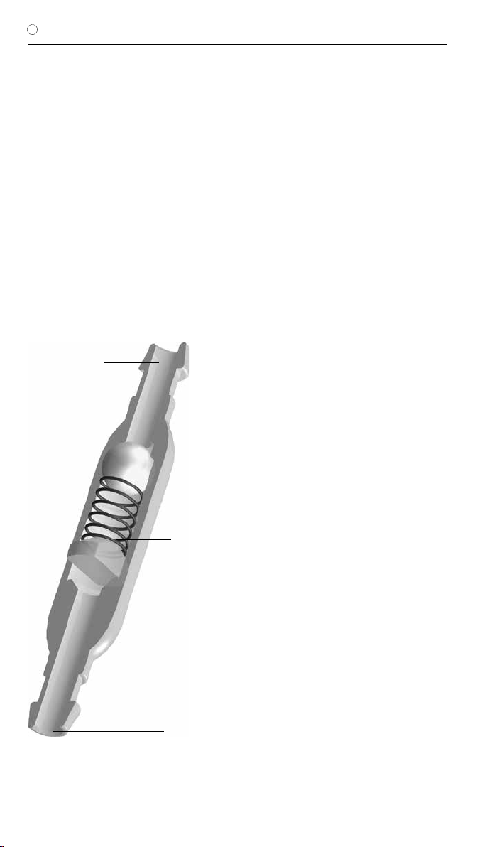
den. Das miniNAV besteht aus einem stabilen
Titangehäuse (1), in das das bewährte Prinzip
eines Kugel-Konus-Ventils integriert ist. Eine
Spiralfeder (2) bestimmt den Öffnungsdruck
des Kugel-Konus-Ventils. Die Saphirkugel (3)
garantiert den präzisen Verschluss. Am distalen
Ventilende ist wahlweise ein Konnektor oder ein
Silikonkatheter angeschlossen. Die Anschluss-
tüllen für den Einlass (4) und den Auslass (5)
sind ebenfalls aus Titan gefertigt.
Abb. 1: Schematische Querschnittszeichnung des miniNAV
4. Einlasstülle
1. Titangehäuse
2. Spiralfeder
5. Auslasstülle
3. Saphirkugel
5
GEBRAUCHSANWEISUNG |D
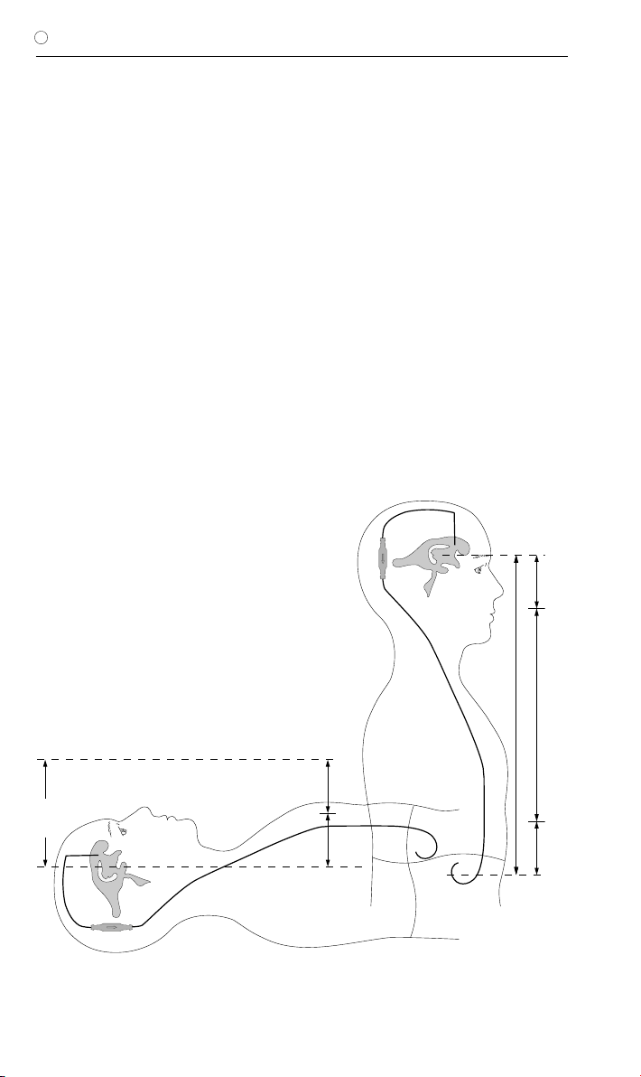
PHYSIKALISCHER HINTERGRUND
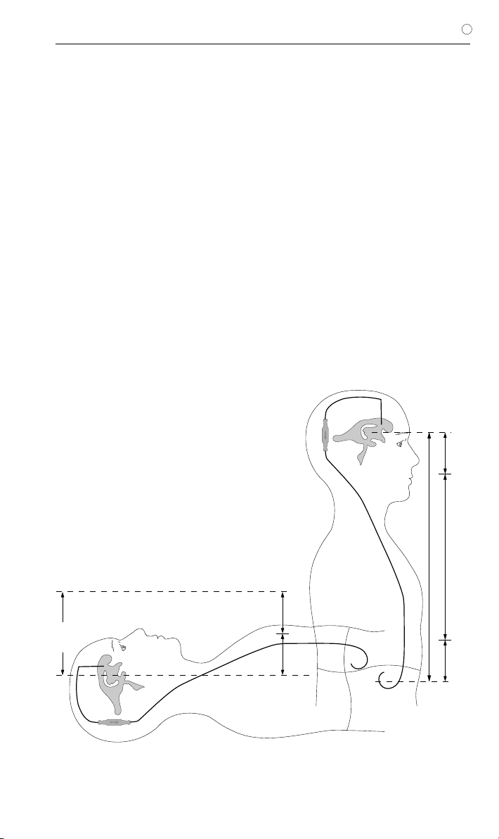
In der liegenden Körperposition errechnet sich
der Druck am Ventil aus der Differenz aus dem
intraventrikulären Druck und dem Druck im
Bauchraum (Abb. 2).
In der liegenden Körperposition ist der in-
traventrikuläre Druck beim gesunden Men-
schen positiv. Um diesen Druck mittels
Ventildrainage einzustellen, ist unter Be-
rücksichtigung des Bauchraumdrucks die
geeignete Druckstufe zu wählen. Dann er-
rechnet sich der IVP aus der Summe des
Ventilöffnungsdrucks und des Bauchhöhlen-
drucks (Abb. 2).
In der stehenden Körperposition wird der Ven-
trikeldruck beim gesunden Menschen leicht
negativ. Um diesen Druck mittels Ventildrainage
einzustellen, muss der Ventilöffnungsdruck weit
höher ausgelegt werden, als in der liegenden
Position nötig wäre. Nur dann kann das Ven-
til den hydrostatischen Druck abzüglich des
Bauchhöhlendrucks und des gewünschten
leicht negativen intraventrikulären Drucks kom-
pensieren.
IVP
PVli
PB
PHyd
PVst
IVP
PB
IVP Intraventrikulärer Druck
PVli Ventilöffnungsdruck im Liegen
(nur Kugel-Konusventil)
PVst Ventilöffnungsdruck im Stehen
(Kugel-Konusventil + Gravitationsventil)
PB Druck in der Bauchhöhle
PHyd Hydrostatischer Druck
Abb. 2: Druckverhältnisse für die liegende und die aufrechte Körperposition.
Liegend: IVP = PVli + PB
Stehend: IVP = PHyd - PVst - PB
6
| GEBRAUCHSANWEISUNG
D
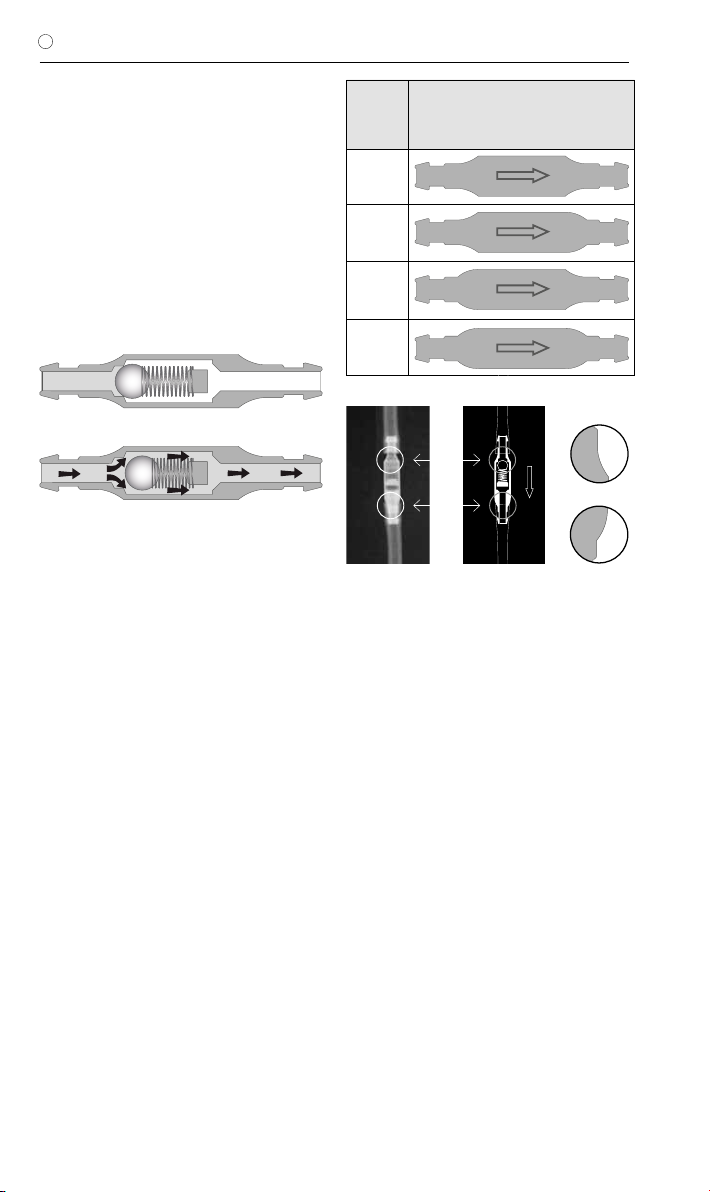
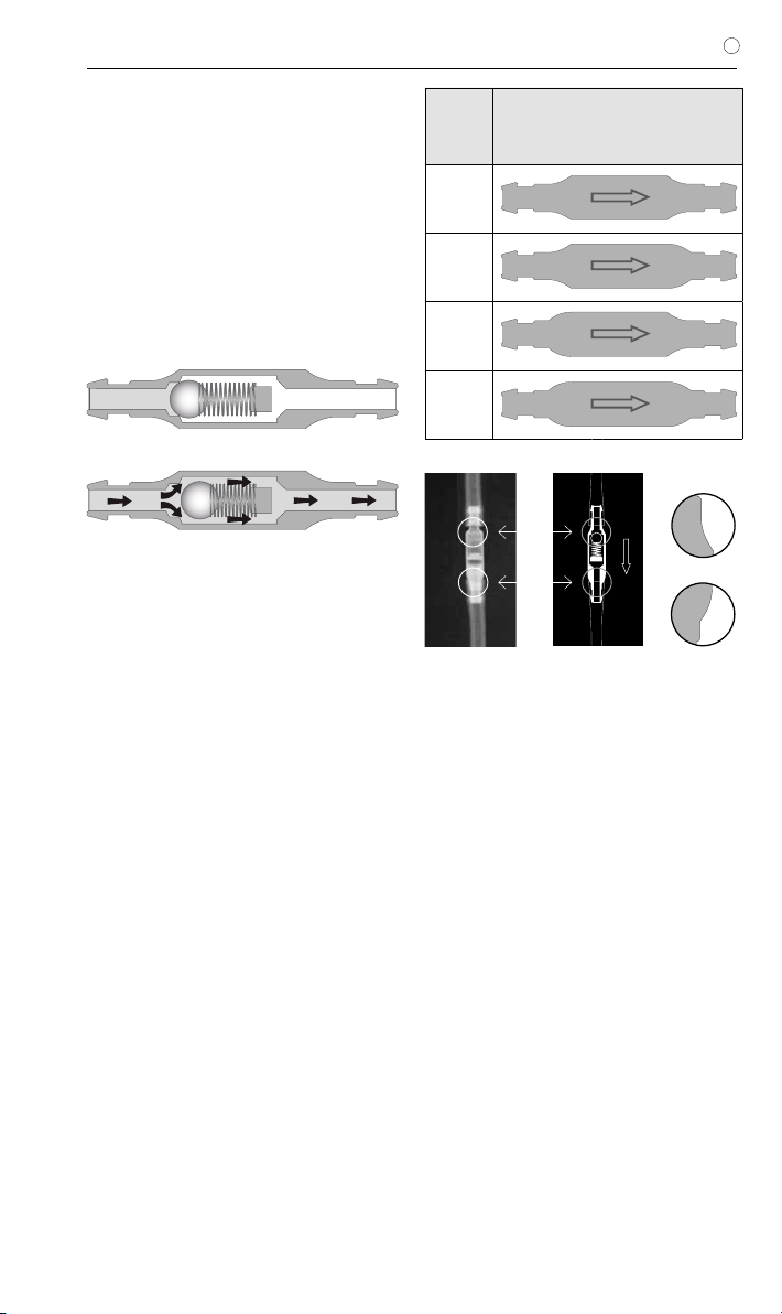
ARBEITSWEISE DES VENTILS
Die prinzipielle Arbeitsweise des miniNAV ist in
Abb. 3 dargestellt. Abb. 3a zeigt das miniNAV
in geschlossener Position. Es ist keine Drainage
möglich.
Wenn der intraventrikuläre Druck den Ventil-
öffnungsdruck übersteigt, wird die Federkraft,
die das Kugel-Konus-Ventil sonst geschlossen
hält, überwunden. Die Feder wird komprimiert,
die Verschlusskugel bewegt sich aus dem Ko-
nus und ein Spalt zur Liquordrainage wird frei-
gegeben (Abb.3b).
b)
Abb. 3: miniNAV
a) geschlossen und b) geöffnet
a)
AUSWAHL DES GEEIGNETEN VENTILS
Der Ventilöffnungsdruck des miniNAVs sollte
entsprechend des Krankheitsbildes ausgewählt
werden.
Wenn der Patient an Überdrainagesymptomen
leidet oder diese Komplikationen erwartet wer-
den, sollte zusätzlich zum miniNAV der SHUNT-
ASSISTANT implantiert werden. Der SHUNT-
ASSISTANT ist ein speziell für die Vermeidung
der Überdrainage entwickeltes Zusatzventil
aus der Produktpalette der Christoph Miethke
GmbH & Co. KG.
Die Kodierung im Röntgenbild erfolgt mittels
der Gehäuseform des Ventils. Hat das Ventil
z.B. eine konkave (nach innen gewölbt) Form
am proximalen Ende und eine konvexe (nach
außen gewölbt) Form am distalen Ende handelt
es sich um die Druckstufe 5 cmH2O (Abb. 4).
Jedes miniNAV wird unter strenger Qualitäts-
kontrolle kalibriert. Die folgenden Druckstufen
sind erhältlich:
Druck-
stufe
(cmH2O)
Kodierung
0
5
10
15
MÖGLICHE SHUNTKOMPONENTEN
Das miniNAV kann in verschiedenen Varianten
bestellt werden. Diese Shuntvarianten besitzen
unterschiedliche Komponenten, die nachfol-
gend kurz vorgestellt werden. Dabei gibt es
Varianten für den kindlichen und weitere für den
Erwachsenen-Hydrocephalus.
Das SPRUNG RESERVOIR oder das Bohrloch-
reservoir werden im Bohrloch der Schädelde-
cke positioniert und bieten die Möglichkeit den
intraventrikulären Druck zu messen, Medika-
mente zu injizieren und Liquor zu entnehmen.
Ein stabiler Titanboden verhindert ein mögliches
Durchstechen des Bodens. Das SPRUNG
RESERVOIR ermöglicht zusätzlich durch ein
Rückschlagventil im Boden, den Liquor in die
ableitende Richtung zu pumpen und damit so-
wohl eine Kontrolle des distalen Drainageanteils
(Reservoir schwer ausdrückbar), als auch des
Ventrikelkatheters (Reservoir füllt sich nach Aus-
drücken nicht erneut) durchzuführen. Während
des Pumpvorganges ist der Zugang zum Ven-
trikelkatheter verschlossen. Der Öffnungsdruck
Abb. 4 Röntgenaufnahme des miniNAV
(Druckstufe 5 cmH2O)
a
b
a
konkav
konvex
b

7
GEBRAUCHSANWEISUNG |D
des Shuntsystems wird durch den Einsatz des
SPRUNG RESERVOIRS nicht erhöht.
Das CONTROL RESERVOIR oder die pädia-
trische Vorkammer werden auf der Schädelde-
cke positioniert und bieten als Vorkammer die
Möglichkeit, den intraventrikulären Druck zu
messen, Medikamente zu injizieren, Liquor zu
entnehmen und eine palpatorische Ventilkon-
trolle durchzuführen. Ähnlich dem SPRUNG
RESERVOIR besitzt das CONTROL RESER-
VOIR ein Rückschlagventil. Der stabile Titanbo-
den verhindert ein mögliches Durchstechen des
Bodens. Eine Punktion sollte möglichst senk-
recht zur Reservoiroberfläche mit einer Kanüle
von max. Ø 0.9 mm erfolgen. Es kann ohne
Einschränkung 30 mal punktiert werden.
Warnhinweis: Durch häufiges Pumpen kann
es zu einer übermäßigen Drainage und da-
mit zu unphysiologischen Druckverhältnis-
sen kommen. Der Patient sollte über diese
Gefahr aufgeklärt werden.
Der Bohrlochumlenker bietet durch seinen
strammen Sitz auf dem Ventrikelkatheter die
Möglichkeit, die in den Schädel eindringende
Katheterlänge vor der Implantation zu wählen.
Der Ventrikelkatheter wird im Bohrloch recht-
winklig umgelenkt (siehe Kapitel „Varianten“).
SCHLAUCHSYSTEME
Das miniNAV ist so konstruiert, dass es nach
Indikation des Arztes den optimalen Ventri-
keldruck sicherstellt. Es kann als miniNAV
SHUNTSYSTEM oder als einzelne Ventileinheit
mit oder ohne integrierten distalen Katheter
(Innendurchmesser 1,2 mm, Außendurchmes-
ser 2,5 mm) bestellt werden. Wird kein Shunt-
system eingesetzt, sollten Katheter mit einem
Innendurchmesser von ca. 1,2 mm und einem
Außendurchmesser von ca. 2,5 mm verwendet
werden. Der Konnektor am Ventil ermöglicht
die Verwendung von Kathetern mit einem In-
nendurchmesser von 1,0 mm bis 1,5 mm. Der
Außendurchmesser des Katheters sollte etwa
dem doppelten Innendurchmesser entspre-
chen. In jedem Fall müssen die Katheter durch
eine Ligatur sorgfältig an den Konnektoren des
Ventils befestigt werden. Knicke in den Kathe-
tern müssen vermieden werden.
Die mitgelieferten Katheter verändern die
Druck-Flow-Charakteristik nicht grundlegend.
OPERATIONSABLAUF
Platzierung des Ventrikelkatheters
Zur Platzierung des Ventrikelkatheters sind ver-
schiedene Operationstechniken möglich. Der
notwendige Hautschnitt sollte bevorzugt ent-
weder in Form eines Läppchens mit Stielung
in Richtung auf den ableitenden Katheter oder
durch einen geraden Hautschnitt erfolgen. Bei
Verwendung des Bohrlochreservoirs sollte der
Hautschnitt nicht unmittelbar über dem Reser-
voir liegen. Es sollte darauf geachtet werden,
dass nach Anlage des Bohrlochs die Öffnung
der Dura möglichst klein erfolgt, um ein Liquor-
leck zu vermeiden.
Der Ventrikelkatheter wird durch den beilie-
genden Mandrin versteift. Wird ein Bohrloch-
umlenker verwendet, kann die zu implantie-
rende Katheterlänge eingestellt und in den
Ventrikel vorgeschoben werden. Nach dem
Entfernen des Mandrins kann die Durchgängig-
keit des Ventrikelkatheters durch Heraustropfen
von CSF geprüft werden.
Der Ventrikelkatheter wird umgelenkt und
mittels Stopfen oder Klemme verschlossen.
Bei Verwendung der Vorkammer wird diese
platziert, wobei die Konnektion des Katheters
mit Hilfe einer Ligatur gesichert werden muss.
Durch eine post-operative CT- oder MR-Auf-
nahme sollte die Positionierung des Ventrikel-
katheters nochmals überprüft werden.
Platzierung des Ventils
Das miniNAV sollte am Kopf implantiert werden.
Das Ventil ist mit einem Pfeil für die Flussrich-
tung nach distal versehen (Pfeil nach unten).
Der Katheter wird vom Bohrloch zum gewähl-
ten Ventilimplantationsort vorgeschoben, wenn
nötig gekürzt und am miniNAV mittels Ligatur
befestigt. Das Ventil sollte sich nicht direkt unter
dem Hautschnitt befinden.
Platzierung des Peritonealkatheters
Der Ort des Zugangs für den Peritonealkatheter
liegt im Ermessen des Chirurgen. Er kann z. B.
waagerecht paraumbilikal oder transrektal in
Höhe des Epigastriums angelegt werden.
Ebenso können verschiedene Operationstech-
niken für die Platzierung des Peritonealkathe-
ters angewendet werden.
Es wird empfohlen, den Peritonealkatheter mit
Hilfe eines subkutanen Tunnelers vom Ventil
aus, eventuell mit einem Hilfsschnitt, bis zum
Ort der Platzierung durchzuziehen.
Abb. 4 Röntgenaufnahme des miniNAV
(Druckstufe 5 cmH2O)
8
| GEBRAUCHSANWEISUNG
D
Der Peritonealkatheter, der in der Regel fest
am miniNAV befestigt ist, besitzt ein offenes di-
stales Ende und keine Wandschlitze.
Nach Darstellung und Entrieren des Peritone-
ums oder mit Hilfe eines Trokars wird der, wenn
notwendig gekürzte, Peritonealkatheter in die
freie Bauchhöhle vorgeschoben.
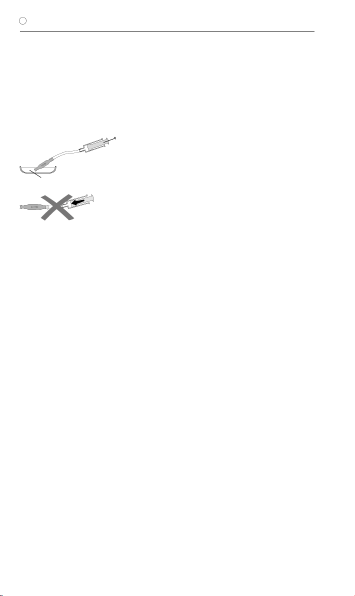
PRÄOPERATIVE VENTILPRÜFUNG
Isotonische Kochsalzlösung
Abb. 5: Durchgängigkeitsprüfung
Das möglichst schonende Befüllen des miniNAV
kann durch Aspirieren mit Hilfe einer am distalen
Katheterende aufgesetzten sterilen Einweg-
spritze erfolgen. Dabei wird das proximale Ende
des Ventils in sterile, physiologische Kochsalz-
lösung gehalten. Lässt sich Kochsalzlösung
entnehmen, ist das Ventil durchgängig (Abb. 5).
Achtung: Eine Druckbeaufschlagung mittels
Einwegspritze sollte sowohl am proximalen
als auch am distalen Ende vermieden wer-
den. Verunreinigungen in der zum Testen
verwendeten Lösung können die Produkt-
leistung beeinträchtigen.
WIEDERHOLUNGSIMPLANTATIONEN
Produkte, die bereits implantiert waren, dürfen
weder bei dem gleichen noch bei bei einem an-
deren Patienten erneut implantiert werden, da
eine valide Reinigung ohne Funktionseinbuße
nicht gelingen kann.
VORSICHTSMASSNAHMEN
Nach der Implantation müssen die Patienten
sorgfältig überwacht werden. Hautrötungen
und Spannungen im Bereich des Drainagege-
webes können ein Anzeichen von Infektionen
am Shuntsystem sein. Symptome wie Kopf-
schmerzen, Schwindelanfälle, geistige Ver-
wirrtheit oder Erbrechen treten häufig bei einer
Shuntdysfunktion auf. Diese Anzeichen, wie
auch eine Leckage am Shuntsystem, erfordern
den sofortigen Austausch der Shuntkompo-
nente oder auch des gesamten Shuntsystems.
VERTRÄGLICHKEIT MIT DIAGNOSTISCHEN
VERFAHREN
Kernspinresonanzuntersuchungen bis zu einer
Feldstärke von 3 Tesla oder computertomogra-
phische Untersuchungen können ohne Gefähr-
dung oder Beeinträchtigung der Ventilfunktion
durchgeführt werden. Das Ventil ist MR verträg-
lich. Die mitgelieferten Katheter sind MR sicher,
Reservoire, Umlenker oder Konnektoren sind
MR verträglich.
POSTOPERATIVE VENTILPRÜFUNG
Das miniNAV ist als funktionssi-
chere Einheit ohne Pump- oder
Prüfeinrichtung konstruiert worden. Es beste-
hen aber Möglichkeiten zum Testen bei Ver-
wendung von Shuntsystemen mit einem Reser-
voir. Die Ventilprüfung kann dann durch Spülen,
Druckmessen oder Pumpen erfolgen.
FUNKTIONSSICHERHEIT
Die Ventile sind konstruiert worden, um über
lange Zeiträume präzise und zuverlässig zu
arbeiten. Es kann jedoch keine Garantie dafür
übernommen werden, dass das Ventilsystem
nicht aus technischen oder medizinischen
Gründen ausgetauscht werden muss. Das Ven-
til und das Ventilsystem halten den während
und nach der Operation auftretenden negativen
und positiven Drücken bis zu 200 cmH2O sicher
stand.

9
GEBRAUCHSANWEISUNG |D
STERILISATION
Die Produkte werden unter strenger Kontrolle
mit Dampf sterilisiert. Durch die Doppel-Verpa-
ckung in Steriltüten ist eine fünfjährige Sterilität
gewährleistet. Das jeweilige Verfallsdatum ist
auf der Verpackung angegeben. Bei Beschädi-
gung der Verpackung dürfen die Produkte auf
keinen Fall verwendet werden.
ERNEUTE STERILISATION
Für die Funktionssicherheit von resterilisierten
Produkten kann keine Garantie übernommen
werden.
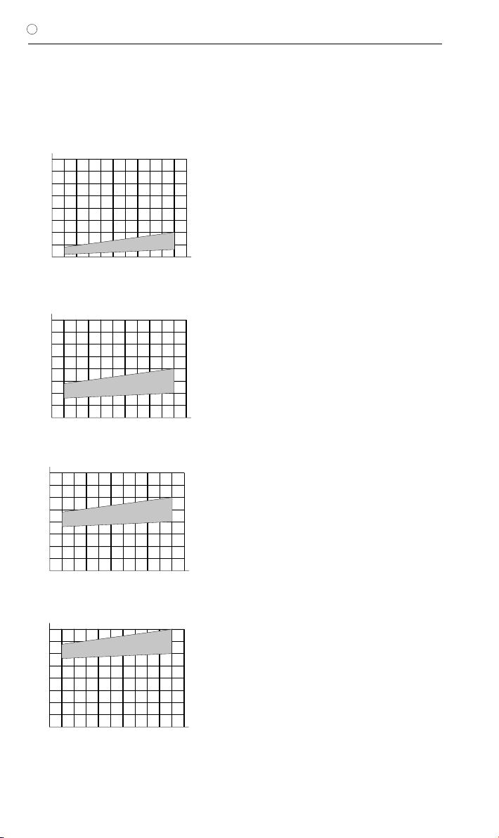
DRUCK-FLOW-CHARAKTERISTIK
Nachfolgend sind die Druck-Flow-Charakteri-
stiken der verfügbaren Druckstufen des miniNAV
dargestellt.
5
10
10 20 30 400 52515 35 45 50 55
15
20
miniNAV 0 cmH2O
Druck ( cmH2O)
Flussrate (ml/h)
Druckstufe 0 cmH2O
5
10
10 20 30 400 52515 35 45 50 55
15
20
miniNAV 5 cmH2O
Druck ( cmH2O)
Flussrate (ml/h)
Druckstufe 5 cmH2O
5
10
10 20 30 400 52515 35 45 50 55
15
20
miniNAV 10 cmH2O
Druck ( cmH2O)
Flussrate (ml/h)
Druckstufe 10 cmH2O
5
10
10 20 30 400 52515 35 45 50 55
15
20
miniNAV 15 cmH2O
Druck ( cmH2O)
Flussrate (ml/h)
Druckstufe 15 cmH2O
Der gesamte Öffnungsdruck bezieht sich auf einen
Referenzflow von 5ml/h. Für Flussraten von 20 ml/h
sind die angegebenen Drücke ca. 1-2 cmH2O höher.
10
| GEBRAUCHSANWEISUNG
D
MEDIZINPRODUKTEBERATER
Die Christoph Miethke GmbH&Co.KG benennt
entsprechend den Forderungen der Medizin-
produkterichtlinie 93/42/EEC vom 14. Juni
1993 Medizinprodukteberater, die Ansprech-
partner für alle produkt-relevanten Fragen sind:
Dipl.-Ing. Christoph Miethke
Dipl.-Ing. Roland Schulz
Christoph Miethke GmbH & Co. KG
Ulanenweg 2
D-14469 Potsdam
Phone: +49(0) 7000 6438453 or
Phone: +49(0) 331 620 83 0
Fax: +49(0) 331 620 83 40
e-mail: [email protected]
Bei Rückfragen wenden Sie sich bitte an:
AESCULAP AG
Am Aesculap Platz
D-78532 Tuttlingen
Tel.:+49 (0) 7461 95-0
Fax:+49 (0) 7461 95-26 00
e-mail: [email protected]
FORDERUNGEN DER MEDIZINPRO-
DUKTERICHTLINIE RL 93/42/EEC
Die Medizinprodukterichtlinie fordert die um-
fassende Dokumentation des Verbleibs von
medizinischen Produkten, die am Menschen
zur Anwendung kommen, insbesondere für
Implantate. Die individuelle Kenn-Nummer des
implantierten Ventils sollte aus diesem Grunde
in der Krankenakte des Patienten vermerkt wer-
den, um eine lückenlose Rückverfolgbarkeit zu
gewährleisten.
KOMMENTAR ZUR GEBRAUCHSANWEI-
SUNG
Die hier ausgeführten Beschreibungen basie-
ren auf den bisher vorliegenden klinischen Er-
fahrungen. Es liegt in der Hand des Chirurgen,
entsprechend seiner Erfahrung und der chirur-
gischen Praxis auf eigene Verantwortung das
OP-Prozedere zu ändern.
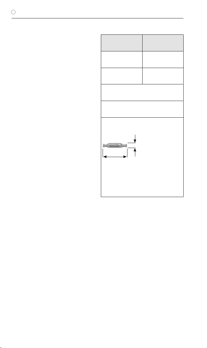
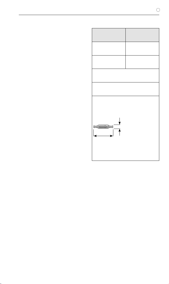
ALLGEMEINE INFORMATIONEN
Hersteller Christoph Miethke
GmbH & Co. KG
Produktbezeichnung miniNAV
Verwendungszweck Behandlung des
Hydrocephalus
Zum einmaligen Gebrauch bestimmt
Trocken und sauber lagern
Skizze des Ventils mit äußeren Abmaßen:
2,8 mm
14,7 mm
Maßstab: 1:1
11
GEBRAUCHSANWEISUNG |D
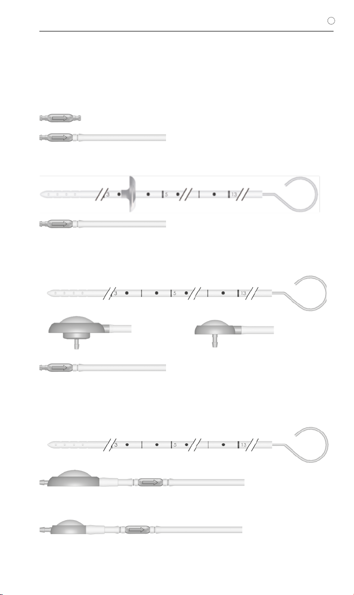
VARIANTEN
Das miniNAV ist als Einzelventil oder als Shunt-
system mit unterschiedlichen Komponenten
erhältlich.
miniNAV
miniNAV SHUNTSYSTEM
miniNAV SHUNTSYSTEM mit SPRUNG
RESERVOIR oder Bohrlochreservoir
(auch für pädiatrische Anwendung)
miniNAV SHUNTSYSTEM mit CONTROL
RESERVOIR oder Vorkammer
(auch für pädiatrische Anwendung)
oder
Maßstab der Grafiken: 1:1
oder

12
| INSTRUCTIONS FOR USE
GB
CONTENT
INDICATION 13
TECHNICAL DESCRIPTION 13
PHYSICS BACKGROUND 14
FUNCTION OF THE VALVE 15
SELECTING THE APPROPRIATE SHUNTSYSTEM 15
POSSIBLE SHUNT COMPONENTS 15
TUBE SYSTEMS 16
SURGICAL PROCEDURE 16
PREOPERATIVE VALVE TEST 17
SAFETY MEASURES 17
RE-IMPLANTATION 17
COMPATIBILITY WITH DIAGNOSTIC PROCEDURES 17
POSTOPERATIVE VALVE TEST 17
STERILISATION 17
RESTERILISATION 17
PRESSURE-FLOW CHARACTERISTICS 18
FUNCTIONAL SAFETY 18
SIDE EFFECTS 18
NOTE ON THE INSTRUCTIONS FOR USE 18
REQUIREMENTS OF THE MDD 93/42/EEC 18
MEDICAL PRODUCTS CONSULTANT 19
GENERAL INFORMATION 19
VARIATIONS 20
13
INSTRUCTIONS FOR USE | GB
INDICATION
The miniNAV is used for draining cerebrospinal
fluid from the ventricles into the peritoneum in
hydrocephalus patients.
TECHNICAL DESCRIPTION
The miniNAV was developed to offer a small-
sized valve without the obstruction related pro-
blems that are known to arise in the treatment
of hydrocephalus.
The miniNAV is composed of a robust titanium
casing (1) whose proximal end contains a ball-
cone valve. A spiral spring (2) maintains the
opening pressure of the ball-cone valve and the
sapphire ball (3) ensures the precise closure of
the valve.
The inlet connector (4) and the outlet connec-
tor (5) are also made of titanium.
Fig. 1: Schematic cross-section of the miniNAV
4. inlet connector
1. titanium housing
2. spiral spring
5. outlet connecotor
3. sapphire ball
14
| INSTRUCTIONS FOR USE
GB
PHYSICS BACKGROUND
The intraventricular pressure is positive in a
healthy human in a the horizontal position. To
maintain this pressure through shunt drainage,
one has to choose the appropriate pressure
range, taking into account the abdominal ca-
vity pressure. The resulting IVP is the sum of
the shunt opening pressure and the abdominal
cavity pressure (fig. 6).
In a healthy human, the ventricular pressure in
the vertical position becomes slightly negative.
To maintain this pressure by means of shunt
drainage, the shunt opening pressure has to be
significantly higher so that the shunt can com-
pensate for the hydrostatic pressure minus the
sum of the abdominal cavity pressure and the
slightly negative intraventricular pressure.
Conventional shunts open immediately as soon
as the patient stands up, which can lead to cri-
tical overdrainage.
Fig. 2: Pressure conditions in horizontal and vertical body positions
IVP
PVli
PB
PHyd
PVst
IVP
PB
IVP Intraventrikular pressure
PVli Opening pressure (hoizontal)
PVst Opening pressure (vertical)
PB Pressure in the abdominal cavity
PHyd Hydrostatic pressure
hoirzontal: IVP = PVli + PB
vertical: IVP = PHyd - PVst - PB
15
INSTRUCTIONS FOR USE | GB
FUNCTION OF THE VALVE
The operating principle of the miniNAV is illus-
trated in fig. 3.
Fig. 3a shows the miniNAV in the horizontal po-
sition. The ball-cone valve is closed and draina-
ge is prevented.
If the patient‘s IVP increases and continues to
rise, the spring pressure of the ball-cone unit
will be overcome. The sealing ball will move
away from the cone and a gap opens for fluid
drainage.
b)
Fig. 3: miniNAV
a) closed and b) open
a)
SELECTING THE APPROPRIATE SHUNT-
SYSTEM
The miniNAV is available in four different pres-
sure pressure levels (0, 5, 10 and 15 cmH2O).
The pressure setting should be chosen accor-
ding to the clinical picture (normal-pressure hy-
drocephalus, hypertonic hydrocephalus).
In case the patient suffers from symptoms as-
sociated with overdrainage, or complicatons
with overdrainage are expected, we recom-
mend implantation of the SHUNTASSISTANT
in addition to the miniNAV. The SHUNTASSI-
STANT is a hydrostatic, supplementary valve
specially designed for preventing problems with
overdrainage. It is made by Christoph Miethke
GmbH & Co. KG.
The coding of the miniNAV can be identified
according to the shape of the valve‘s housing.
For example the miniNAV with an opening pres-
sure of 5 cmH2O has a concave proximal part
(curved inwards) and a convex distal part (cur-
ved outwards). (Fig. 4)
Each miniNAV is calibrated in accordance with
strict quality control standards. The following
pressure levels are available:
pressure
rating
(cmH2O)
Coding
0
5
10
15
a
b
a
concave
convex
b
POSSIBLE SHUNT COMPONENTS
The miniNAV is available with different shunt
accessories. These variations are comprised of
a variety of components, which are described
briefly introduced below:
The borehole reservoir is positioned in the cra-
nial borehole. It allows measurement of intra-
ventricular pressure, injection of drugs and ex-
traction of CSF. Its solid titanium base is highly
puncture-resistant. All reservoirs are available
with integrated catheters or connectors. A spe-
cial borehole reservoir is the SPRUNG RESER-
VOIR. An additional new feature of this reservoir
is that CSF can be flushed towards the miniNAV
because of a non-return valve in the bottom of
the reservoir. By this mechanism, flow in the di-
rection of the ventricular catheter is avoided du-
ring the pumping procedure. The opening pres-
sure of the shunt system is not increased by
the implantation of the SPRUNG RESERVOIR.
Fig. 4: X-ray image of the miniNAV
(pressure rating 5 cmH2O)

16
| INSTRUCTIONS FOR USE
GB
The prechamber is positioned on the cranium.
It allows measurement of intraventricular pres-
sure, injection of drugs, extraction of CSF and
palpatory ventricle inspection. Its solid titanium
base is highly puncture-resistant. A puncture of
the prechamber or the CONTROL RESERVOIR
should be performed as perpendicular to the
reservoir surface as possible with a cannula
of maximum diameter 0,9mm. 30 punctures
are possible without any restrictions. A special
prechamber is the CONTROL RESERVOIR. As
an additional new feature of this reservoir, CSF
can be flushed towards the miniNAV because
of a non-return valve in the proximal inlet of the
reservoir. By this mechanism, flow in the direc-
tion of the ventricular catheter is avoided during
the pumping procedure. The opening pressure
of the shunt system is not increased by the im-
plantation of the CONTROL RESERVOIR.
Warning note: Frequent pumping can lead
to overdrainage and thus to pressure con-
ditions outside the normal physiological
range. The patient should discuss the risks
(involved) with their surgeon.
Tight tolerancing of the deflector ensures a
good fit with the ventricular catherther. By ad-
justing the deflector (prior to implantation) the
length of catheter penetrating into the skull can
be optimised. The ventricular catheter is “de-
flected” at a right angle in the borehole (see
chapter “Variations”).
TUBE SYSTEMS
The miniNAV has been designed to ensure the
optimal ventricular pressure. It is available as a
shunt system or as individual valve units with
or without an integrated distal catheter (internal
diameter 1.2 mm, external diameter 2.5 mm).
Individual valve units should be used with ca-
theters of approx. 1.2 mm internal diameter and
approx. 2.5 mm external diameter. The connec-
tor on the valve allows using catheters of 1.0
mm to 1.5 mm internal diameter. The external
diameter of the catheter should be about dou-
ble the internal diameter. Regardless, the ca-
theters must be carefully fixed, with a ligature,
to the valve connectors. It is essential that kinks
in the catheter are avoided.
The included catheters have virtually no effect
on the Pressure-flow characteristics.
SURGICAL PROCEDURE
Positioning the ventricular catheter
Several surgical techniques are available for po-
sitioning the ventricular catheter. The necessary
skin incision should be carried out, preferably,
in the shape of a lobule pedicled towards the
draining catheter or as a straight skin incision.
To avoid CSF leakage, care should be taken
that the dura opening is kept as small as possi-
ble after applying the borehole. The ventricular
catheter is stiffened by the introducing stylet
supplied with the product.
The miniNAV is available in different shunt va-
riations:
When using a miniNAV SHUNTSYSTEM with
borehole reservoir or SPRUNG RESERVOIR,
the ventricular catheter is implanted first. Once
the introducing stylet has been removed, the
patency of the ventricular catheter can be te-
sted by checking if CSF is dripping out. The ca-
theter is shortened and the borehole reservoir is
connected, with the connection secured with a
ligature. The skin incision should not be located
directly above the reservoir.
The miniNAV SHUNTSYSTEM with precham-
ber or CONTROL RESERVOIR comes with a
deflector. This deflector is used for adjusting the
position of deflection before implantation of the
ventricular catheter. The catheter is deflected;
the prechamber is put into place. The position
of the ventricular catheter should be inspected
again by postoperative CT or MR imaging.
Positioning the miniNAV
The miniNAV should be implanted in the head
of the patient.
The valve is marked with an arrow pointing to
distal (downwards) to indicate the flow direc-
tion. Whether the label faces towards the skin
or the brain is of no importance in terms of the
valve‘s performance.
Following subcutaneous tunneling, the catheter
is either pushed from the borehole, possibly
through a reservoir, to the selected valve im-
plantation site; or it is pushed through from the
valve and connected to the reservoir, if there is
any.
Positioning the peritoneal catheter
The access site for the peritoneal catheter is left
to the surgeon’s discretion. It can be applied
e. g. para-umbilically in a horizontal direction or

17
INSTRUCTIONS FOR USE | GB
transrectally at the height of the epigastrium.
Likewise, various surgical techniques are
available for positioning the peritoneal catheter.
We recommend pulling through the peritoneal
catheter, using a subcutaneous tunneling tool
and perhaps with an auxiliary incision, from the
shunt to the intended position of the catheter.
The peritoneal catheter, which is usually secu-
rely attached to the miniNAV, has an open distal
end, but no wall slits. Following the exposure
of, and the entry into, the peritoneum by means
of a trocar, the peritoneal catheter (shortened,
if necessary) is pushed forward into the open
space in the abdominal cavity.
PREOPERATIVE VALVE TEST
Isotonic sterile sodium chloride solution
Fig. 5: Patency test
The miniNAV can be filled by aspiration through
a sterile, single-use syringe attached to the di-
stal end of the catheter. The proximal end of
the valve is immersed in a sterile, physiological
saline solution. The valve is patent if fluid can be
extracted in this way (see Fig. 5).
Caution: Pressure admission through the
single-use syringe should be avoided, both
at the proximal and the distal end.
Contaminations in the solution used for the
test can impair the product’s performance.
SAFETY MEASURES
The patients must be carefully monitored after
the implantation. Reddened skin and tension in
the area of the drainage tissue could indicate
infections at the shunt system. Symptoms such
as headache, dizzy spells, mental confusion or
vomiting are common occurrences in cases of
shunt dysfunction. Such symptoms, as well as
shunt system leakage, necessitate the imme-
diate replacement of the shunt component re-
sponsible, or of the entire shunt system
RE-IMPLANTATION
Under no circumstances should products that
have had previously been implanted in a pati-
ent be subsequently reimplanted in another,
because a successfull decontamination of the
device cannot be reached without functional
degradation.
COMPATIBILITY WITH DIAGNOSTIC PRO-
CEDURES
MRI examinations with field strengths of up to
3.0 tesla and CT examinations can be carried
without endangering or impairing the functiona-
lity of the shunt. The miniNAV is MR Conditional
(ASTM-F2503-08). All components are visible
via X-ray. The provided catheters are MRI Safe.
Reservoirs, deflectors and connectors are MR
Conditional.
POSTOPERATIVE VALVE TEST
The miniNAV has been designed as a safe and
reliable unit even without the implantation of a
pumping device. However, the inclusion of a
prechamber or a borehole reservoir allows the
shunt system to be tested by flushing or pres-
sure measurements.
STERILISATION
The products are sterilized with steam under
closely monitored conditions. Double wrapping
in sterile bags ensures sterility for a period of
five years. The expiry date is printed on the
wrapping of each individual product. Products
taken from a damaged wrapping must not be
used under any circumstances.
RESTERILISATION
The functional safety and reliability of resterilized
products cannot be guaranteed, therefore re-
sterilisation is not recommended.
18
| INSTRUCTIONS FOR USE
GB
PRESSURE-FLOW CHARACTERISTICS
The diagrams below show the pressure-flow
characteristics for the pressure ratings in which
the miniNAV is available.
5
10
10 20 30 400 52515 35 45 50 55
15
20
miniNAV 0 cmH2O
Pressure ( cmH2O)
Flow (ml/h)
Pressure rating 0 cmH2O
5
10
10 20 30 400 52515 35 45 50 55
15
20
miniNAV 5 cmH2O
Pressure ( cmH2O)
Flow (ml/h)
Pressure rating 5 cmH2O
5
10
10 20 30 400 52515 35 45 50 55
15
20
miniNAV 15 cmH2O
Pressure ( cmH2O)
Flow (ml/h)
Pressure rating 15 cmH2O
5
10
10 20 30 400 52515 35 45 50 55
15
20
miniNAV 10 cmH2O
Pressure ( cmH2O)
Flow (ml/h)
Pressure rating 10 cmH2O
The total opening pressure refers to a reference flow of
5 ml/h. When the flowrates reach 20 ml/h, the opening
pressures are approximately 1-2 cmH2O higher.
FUNCTIONAL SAFETY
The valves have been designed for long-term
reliable and precise operation. Still, the possi-
bility that the shunt system will need to be re-
placed for technical or medical reasons cannot
be excluded.
The valve and the valve system are able to re-
sist positive and negative pressure up to 200
cmH2O during and after implantation.
NOTE ON THE INSTRUCTIONS FOR USE
The descriptions and explanations given in this
document are based on the clinical experience
available to date. It is for the surgeon to deci-
de if surgical procedures should be changed
according to his or her experience and to sur-
gical practice.
REQUIREMENTS OF THE MDD 93/42/EEC
The MDD calls for the comprehensive docu-
mentation of the whereabouts of medical pro-
ducts that are applied in human beings, es-
pecially the whereabouts of implants. For this
reason, the individual identification numbers
of any implanted valves are to be noted in pa-
tients‘ records, so that in the event of any in-
quiries, the implant can be traced without any
difficulties. Each valve is outfitted with a sticker
for this purpose.
19
INSTRUCTIONS FOR USE | GB
MEDICAL PRODUCTS CONSULTANT
In compliance with the requirements of the Eu-
ropean law MDD 93/42/EEC, Christoph Mieth-
ke GmbH&Co.KG names medical product con-
sultants as the individuals to be addressed with
all queries concerning the products:
Dipl.-Ing. Christoph Miethke
Dipl.-Ing. Roland Schulz
Christoph Miethke GmbH & Co. KG
Ulanenweg 2
D-14469 Potsdam
Phone: +49(0) 7000 6438453 or
Phone: +49(0) 331 620 83 0
Fax: +49(0) 331 620 83 40
e-mail: [email protected]
Please address any enquiries to:
AESCULAP AG
Am Aesculap Platz
D-78532 Tuttlingen
Phone: +49 (0) 7461 95-0
Fax: +49 (0) 7461 95-26 00
e-mail: [email protected]
Service address in the US
AESCULAP Inc.
Attn. AESCULAP Technical Services
615 Lambert Pointe Road
Hazelwood, MO, 63042
AESCULAP Repair Hotline
Phone: +1 (800) 214-3392
Fax: +1 (314) 895-4420
Distributor in the US/ Contact in Canada
AESCULAP Inc.
3773 Corporate Parkway
Center Valley, PA 18034
Phone: +1-800-282-9000
www.aesculapusa.com
GENERAL INFORMATION
Manufacturer Christoph Miethke
GmbH & Co. KG
Product name miniNAV
Intended use Treatment of
hydrocephalus
Intended for one-time use (disposable)
Store in a clean, dry place
Schematic representation of the shunt with its external
dimensions:
2,8 mm
14,7 mm
scale: 1:1

20
| INSTRUCTIONS FOR USE
GB
VARIATIONS
The miniNAV is available as a single valve or as a
shunt system comprising various components.
miniNAV
miniNAV SHUNTSYSTEM
miniNAV SHUNTSYSTEM with SPRUNG
RESERVOIR or with borehole reservoir
(adult and pediatric)
miniNAV SHUNTSYSTEM with CONTROL
RESERVOIR or with prechamber
(adult and pediatric)
or
scale: 1:1
or
Table of contents
Languages:
Other MIETHKE Medical Equipment manuals


