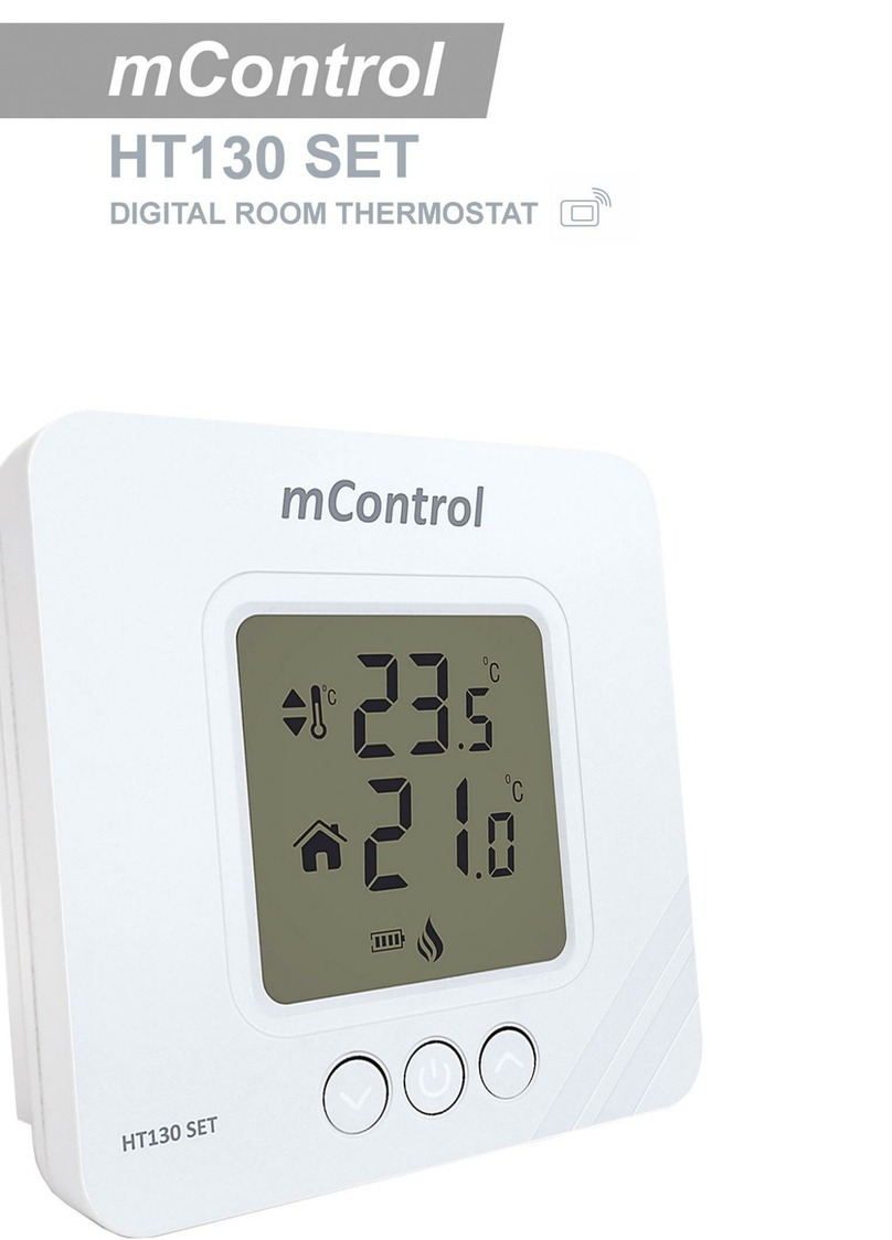
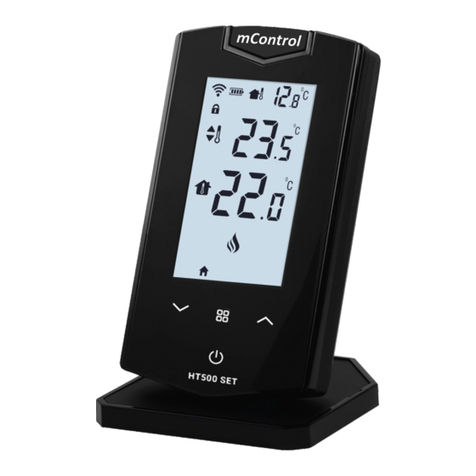
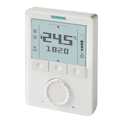
MIKOTERM mControl HT300 SET User manual


THE CONTENT
1. HOW THE WORKS HT300SET
1.1 TECHNICAL DATA
1.2 HT300 SET ROOM THERMOSTAT-symbols and buttons
2. INSTALLATION HT300 SET ROOM THERMOSTAT
2.1 HT300SET RECEIVER EQUIPMENT
2.2 HT300SET RECEIVER
2.3 HT300SET RECEIVER INSTALLATION
2.4 CONNECTION SCHEME
2.5 HT300SET RECEIVER CONNECTION
2.6 THE MEANING OF THE COLORS OF THE RECEIVER LIGHT
3. THERMOSTAT SYNCHRONIZATION PROCEDURE WITH RECEIVER
3.1 THERMOSTAT ADJUSTMENT
3.2 PROGRAM MODE SETTING
3.3 CALIBRATION OF ROOM THERMOSTAT
4. DECLARATION OF CONFORMITY
4.1 FIELDS OF APPLICATION
4.2 WARRANTY CONDITIONS

1. HOW IT WORKS HT300 SET
The HT300 SET wireless room thermostat is used in heating systems to keep the set room temperature constant. It is
compatible with all models of On-Off boilers. The thermostat can be set to a specific temperature for the period of time
the user wants, providing comfort as well as energy savings. Function display is via LED backlit display. You control the
functions via the lockable touch keys. The HT300 SET has three modes: 1. comfort, 2. economy and 3. holiday mode,
also has the ability to adjust the daily and weekly program.
1.1 TECHNICAL DATA
Room Thermostat - Technical Data
Operating Current
3V DC (2 x AAA alkaline batteries)
Dimensions
88mm / 136mm / 29mm
Feeding Voltage
2A (30V DC)
Temperature Measurement Accuracy
0.1 °C
Operating Sensitivity
0.5 °C
Operating Temperature Range
(5 °C) –(30 °C)
Battery Life
1 years (2 x AAA)
Operating Temperature
(-10 °C) –(+50 °C)
Storage Temperature
(-20 °C) –(+60 °C)
Receiver - Technical Data
Operation Current
220V (AC)
Dimensions
80mm / 90mm / 28.5mm
Relay NO Switching Current
6A (220V AC)
Operating Temperature
(-10 °C) –(+50 °C)
Storage Temperature
(-20 °C) –(+60 °C)
1.2 HT300 SET ROOM THERMOSTAT
Set temperature
Room temperature
Battery Indicator
Boiler indicator
Temperature Set Button
(Increase)
Temperature Set
Button (Reduce)
ON/OFF Button
Night mode
Key lock
Mode key
Programmed mode
Settings
Image 1

2. ROOM THERMOSTAT PLACEMENT
Place your room thermostat in a room where you most use it as your living area. For example: living room. Avoid
installing the room thermostat where there is a lot of air circulation such as door entry or window edges. Also, do not
place in places near heat units (central heating system, fireplace, etc.) and places that receive direct sunlight. We
recommend that the room thermostat be placed at an altitude of 50 cm to 150 cm from the floor. You can try a few
places to find the most suitable place.
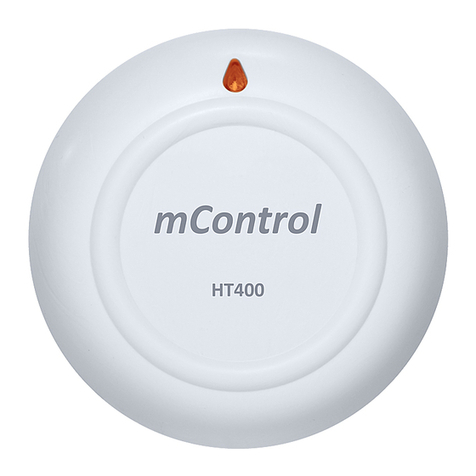
2.1 HT300SET RECEIVER EQUIPMENT
HT300 SET Reciver
Power Cable
Pegs and Screws
Image 2
Image 3

2.2 HT300 SET RECIVER
2.3 HT300 SET RECEIVER PLACEMENT
The important thing to note in the HT300 SET receiver placement is that avoiding physical contact with boiler and
protecting against materials such as liquid, dust etc. You can place your receiver in boiler's cabinet without physical
contact with boiler or mount receiver to wall by using Receiver.
Image 4

2.4 CONNECTION SCHEME
2.5 RECEIVER SETUP
First, shut down electrical current which your boiler is connected (fuse, power outlet etc.)
Connect one of the boiler connection cable to receiver as shown in the Connection Scheme.
Connect other boiler connection cable end to boiler's room thermostat input as shown in the boiler's user manual.
Input Receiver power cable first to receiver than to plug. If there is no plug near your boiler, you can connect cable
to your boiler's connection fuse.
After finishing connections, turn on electrical current first, then turn on your boiler.
If you want to deactivate your receiver, press manual button for 2 seconds then you should see orange light on
receiver. After being sure that your boiler is working, press same button and see orange light disappeared.
Setup Room Thermostat to sync receiver with room thermostat.
Warning!
Only persons who have got Professional Competence should make operations electric wiring or boiler setup.
At the following link, you can watch a video that describes in detail the procedure for connecting the receiver:
https://www.youtube.com/watch?v=EPZexrCDGdA
or on the Mikoterm YouTube channel which you can reach
through our site
or by loading the following QR code:
Image 5

2.6 RECEIVER LED LIGHT COLOR EXPLANATIONS
Green
Receiver synced with thermostat and Works properly.
Green Flashing
Pressed to receiver sync button and waiting for thermostat sync signal.
Red
Receiver has energy but no thermostat synced.
Red Flashing
Boiler shut down because no signal from thermostat more than 22 minute.
Orange
On Manual Mode.
3. THERMOSTAT SYNCHRONIZATION PROCEDURE WITH RECEIVER
After you have properly connected the receiver to the boiler, you need to synchronize the thermostat with the receiver.
Note: Be sure to insert the batteries necessary for the thermostat to work into the thermostat.
Important: See Image 1 and key names before starting the synchronization.
Thermostat synchronization procedure with receiver:
1. Hold down the thermostat on button for a few seconds after which the thermostat calibration temperature will appear
on the screen.
2. Then briefly press the thermostat on button again and "Adr" will appear on the screen..
3. Then hold the sync button on the receiver until the light on the receiver starts blinking green.
4. Immediately after that, press the down arrow key „„ and the thermostat will turn off.
5. Finally, switch on the thermostat by briefly pressing the power button.
6. Wait 10-15 seconds, after which the receiver will sound, which is a sign that the synchronization has been completed
successfully.
Watch the video in the chapter 3.2
3.1 THERMOSTAT ADJUSTMENT
Important: before starting to set the thermostat, see image 1 and the names of the buttons.
The thermostat locks automatically if no function is set for 5 seconds. If the thermostat is locked, unlock the thermostat
by holding down the operating mode button for 3 seconds.
To enter the thermostat setting, hold down the setting button for 3 seconds. The current time setting appears first, which
you can adjust using the button down „“ or up „“. Once you have set the correct hours, short-click the set button
to go to the minute setting. Each time you click on the adjust button, you move to the next parameter, which you can
also adjust using the button down „“ or up „“:
day of the weeki (1- Monday, 2- Tuesday,...,7- Sunday),
temperature for comfort mode,
temperature for economy mode,
temperature for the holiday mode.
Finally, to save the settings, hold down the setting button for 3 seconds.
3.2 PROGRAM MODE SETTING
Important: before starting to set the thermostat, see image 1 and the names of the buttons.
The operation of the program mode is based on the temperature change you set for the economical and comfort mode
in the previous chapter. To enter the program mode settings, hold down the program mode button for 3 seconds.
Example settings
1:
1-Monday (use the adjustment key to change the day of the week),
economy mode - image of the crescent (using the mode buttons change the economy or comfort mode in the
program mode setting option),
you start by setting the time from 00h-08h (using the up arrow). At 08h change to a comfort mode.
You have thus set that when your program mode is active on Monday from 00h-08h the boiler works in economy mode
2:
Monday is still set it doesn't change,
change to comfort mode - sun image (use the mode buttons to change the economy or comfort mode in the
program mode setting option),
you start by setting the time from 08h-00h (using the up arrow). At 00h change to economy mode.
Thus, you set that when your program mode is active on Monday from 08h-23hi59min. the boiler operates in a comfort
mode.

3:
now your screen has automatically changed to Tuesday-2, because you reached the 00h the next day with the
arrows,
change to economy mode - crescent image (use mode keys to change economy or comfort mode in program
mode setting option),
you start by setting the time from 00h-08h (using the up arrow). At 08h change to a comfort mode.
You have thus set that when your program mode is active on Tuesday from 00h-08h the boiler works in economy mode.
4:
Tuesday is still set it doesn't change,
change to comfort mode - sun image (use the mode buttons to change the economy or comfort mode in the
program mode setting option),
you start by setting the time from 08h-00h (using the up arrow). At 00h change to economy mode.
You have thus set that when your program mode is active on Tuesday from 08h-23hi59min. the boiler operates in a
comfort mode.
We have thus set the program mode for Monday and Tuesday. It is necessary to set the program mode for each day of
the week.
Finally, to save the settings, hold down the program mode button for 3 seconds.
Note: to use the program mode, after saving the program mode settings, you need to activate this mode using the mode
keys.
Important-setting mode:
Use the operating mode button to change modes (comfort, economical, holiday or program). Pressing the down arrows
„“ or up „“, you return to manual mode.
At the following link you can watch a video that describes in detail the procedure for synchronizing
the thermostat with the receiver, setting the thermostat and program mode:
https://www.youtube.com/watch?v=GgAsjDBYSik&t
or on the Mykoterm YouTube channel which you can reach
through our site
or by loading the following QR code:
3.3 CALIBRATION OF ROOM THERMOSTAT
Temperature sensors used for room thermostats are very sensitive. No other thermometer in your living room has such
sensitivity. You can calibrate the room thermostat if you want to get the temperature of other thermometers in your living
space.
When the unit is turned off, press the ON / OFF button for 3 seconds.
To see the desired temperature, adjust the temperature difference by pressing the button down „“ or up „“.
This value can be set between -8oC and + 8oC.
Exit the menu by pressing the ON / OFF button.
Note: The recommended temperature calibration is „0,0oC“.

4. DECLARATION OF CONFORMITY
Brand: mControl
Product Name: HT300 SET
Product Type: Wireless room thermostat
Compatible Directives:
Radio and Telecommunications Terminal Equipment Regulation 2014/53/EU (R&TTE/RED EN 301 489-1 V2.1.1:2017,
EN 300 220-1 V3.1.1:2017, EN 301 489-3 V2.1.1:2017, EN 300 220-2 V3.1.1:2017, EN 62479: 2010, EN 60730-2-
9:2010, EN 60730-1:2011)
Electromagnetic Compatibility Regulation 2014/30/EU (EMC EN 61000-6-3: 2007 + A1: 2011, EN 61000-6-1: 2007
Low Voltage Directive 2014/35/EU (LVD EN 60730-2-9:2010, EN 60730-1:2011)
4.1. FIELDS OF APPLICATION
Residential, Flats, Commercial Areas, Light industrial buildings, Zone valves, Thermal valves, Gas or oil burners, Fans,
Pumps
4.2 WARRANTY CONDITIONS
1. Warranty starts at the delivery date of devices and equpments and warranted against manufacturing defect for 2
years.
2. Devices and equipments are delivered to customers in operation. Mounting and other connections will be additional
fee for service.
3. Devices will maintenance and repair in our factory and should send by contracted transportation company. For out
services, transportation and accommodation of service personnel are covered by customers. Overtime is added on
service charge and is received as cash proceeds.
4. Maintenance of devices and equipments will be in our factory. For device maintenance, the round travel fares are
covered by customers.
5. If devices are malfunction in warranty duration, devices will be inspected in our factory to find out whose
responsibility (manufacturer or customer) and will announce to user by report.
6. Devices, which malfunctioned in warranty duration and found out it is responsibility of manufacturer, customer can
demand new product or repair which all costs will fulfilled by manufacturer regarding to cost is not higher than
device.
7. After inspection of malfunction and detected that, it is customer's fault, repair cost of the device which still in warranty
duration will be customer's responsibility.
8. Customers should be aware of damages (if there is any) of product and warn manufacturer since the day warranty
duration starts. If customer do not warn manufacturer with knowledge of damage, customer lose the rights of article
6.
9. Devices and equipments should be used as specified in User's Manual if not used as specified, products are out of
warranty.
10. If products damaged, scratched or cracked by customer. The products will be out of warranty conditions.
11. Damages/Malfunctions because of using other brand' s and model' s devices and equipments without knowledge
of manufacturer are out of warranty.
12. The arising depredation owing to working in humid and acidic places and result of rusting, oxidation is out of
warranty.
13. The transport damage is out of warranty. Customers can take a transportation insurance.
14. Damages by virtue of grid voltage are out of warranty.
15. Damages because of force majeure like flood, earthquake, fire etc. are out of warranty.
16. All parts of the product are under warranty of our company.
17. If product breaks down and gets fixed in warranty duration, duration of maintenance adds to the warranty duration.
Products repairment can't exceed 20 work days. This duration starts when the product's problems are reported to
the seller, agency, producer or the importer if there is no service station. Consumer can report the problem by; fax,
e-mail, registered and reply paid letter or a similar way. If a conflict happens, the consumer has the responsibility of
proofing it. If the problem can't be solved more than 10 days the producer or importer has to supply a similar device
until end of the reparation. If the product breaks down because of material, label or mounting faults in the warranty
duration, firm won't demand label costs, changing parts or any other kind of charge for repairment.
18. Despite consumers rights of maintenance;
-If the product breaks down for 4 times in a year or 6 times in warranty duration and these problems effects main
purpose of the product. (starting from delivery time during warranty.),
-Exceeding the maximum repairing term,
-In the case of not existing service station, determining that repairment is not possible with the report compiled by
respectively service station's seller, dealer, agency, legation, importer or manufacturer.
19. Warranty document should be kept by customer until warranty duration is finished. If warranty is lost there will be
no replacement. All maintance and repair cost is responsibility of customer in case of warranty document lost.
Table of contents
Other MIKOTERM Thermostat manuals
Popular Thermostat manuals by other brands

Trane Technologies
Trane Technologies BAYSTAT152A Installation, operation and maintenance
Worcester
Worcester GREENSTAR 25 HE instruction manual
Nibe
Nibe RG 10 installation instructions
Lauda
Lauda P 10 Operation manual

Center
Center 340023 installation manual
Beok Controls
Beok Controls TGR-86 quick start guide
